Attachments for High-Temperature Insulation Systems
Time and energy are spent on writing and designing insulation systems, but very little is spent on the specifics of the attachments that hold these systems together. All insulation systems for flat plate areas, boiler walls or piping systems require attachments.
A high-temperature system application is defined as operating above 350 F. For the power generating industry, that would encompass the outside of the boiler, penthouse, economizer, wind box, secondary air duct, gas outlet flue to the air heater (which can include selective catalytic reducers, non-catalytic reducers, scrubbers and precipitators), air heater, gas recirculating flue, pulverizers, primary air duct and some piping systems (i.e., downcomers, steam leads, soot blowers, supplies and feed water piping). Any insulation system will fail without the right accessories and attachments for these high-temperature applications.
There are many different types of insulation and lagging systems used in the power generating industry for high-temperature applications. Listed below is a quick review of the most common insulation and lagging systems used for high-temperature applications.
- H-bar system – This system uses a prefabricated support system much like the manufactures of continuous gutters. These steel channels are attached to the external surface of the stiffeners and form a picture frame in which the insulation sits. The lagging will then be attached (screwed) to the framework. The attachments and accessories that are required for this type of application include expanded metal lath, lagging screws and caulking.
- Standoffs with sub-girt – This system uses a standoff to support the outer lagging. The standoffs can be either studs or angle irons. In both cases the standoff is welded to the plate, stiffener or pressure part. The lagging support is then attached to the standoffs. This lagging support can either be a channel sub-girt or angle iron. The insulation is supported independently with insulation pins and clips. The attachments and accessories that are required for this type of application include knurled studs, drive plates, angle irons, lagging screws, sub-girt, caulking, insulation pins and speed clips.
- Insulation pins and sub-girt – This system uses insulation pins and a perforated sub-girt to attach the insulation and lagging. The attachment and accessories that are required for this type of application include lagging screws, sub-girt, caulking, insulation pins and speed clips.
- Pre-insulated lagging panels – This system consists of a shop or field-fabricated insulated lagging panel. This panel will then be attached to the outside of the stiffeners directly or to an angle iron subsystem. The attachment and accessories that are required for this type of application include lagging screws, sub-girt, caulking, insulation pins and speed clips.
- Piping System – This system consists of pipe insulation covered by jacketing. The attachment and accessories that are required for this type of application include pipe jacketing screws, lacing wire, bands and caulking.
There are many other systems composed of, in combination with, or similar to any or all, of the above systems for high-temperature application, for example, inner lagging over stiffeners with a pin and sub-girt application, or a H-bar and pre-insulated panel combination.
Without exception, attachments and accessories make up, hold or support the insulation, lagging and jacketing materials required to make that system thermally and energy efficient. The closer you pay attention to the attachments and accessories, the better the insulation and lagging system being installed.
Insulation Attachments
Insulation pins being used with an insulation material that can be impaled should be mild steel and copper-coated to prevent rusting, 10 or 12-gauge, and capacitor-discharge type. It is not recommended to use zinc-coated insulation pins except when using a pre-insulated panel because they have the potential for a high weld-failure rate when welding to carbon steel casing. The length of the insulation pin should be a minimum of 1 inch longer than the thickness of the insulation being held, and only use a 10-gauge pin if using the insulation pins as part of the lagging support system.
Insulation speed clips being used with insulation pins for holding insulation in place should be 2½-inch square mild steel, 12-gauge material and zinc-coated to prevent rusting.
Acoustical hanger clips being used with wiring hard block or board insulation that cannot be impaled should be capacitor-discharge type, mild steel and a minimum of 1-1/8 inches long. The acoustical hanger has a small hole at the top for looping lacing wire to hold the hard insulation block in place.
Lacing wire being used for holding hard block or board insulation that cannot be impaled or for lacing insulation blanket edges together should be a 14-gauge, soft annealed material. This material should be either stainless steel (where temperatures are 850 F and greater) or carbon steel (where temperatures are less than 850 F). See Figure 1 for a typical lacing wire chart.
Adhesives
Adhesives should be used for attaching high temperature flexible insulation to the top stiffener flanges. High temperature flexible insulation is required when the outer lagging is installed directly to the stiffener flange or angle standoffs. (The insulation will help prevent heat transfer from the stiffener or angle flange to the outer lagging material.)
Caulking
Aluminastic sealing compound is a caulking material used for sealing gaps or openings on jacketing or lagging to prevent water penetration. Sealing by caulking is permissible when within temperature limitations and expected expansion.
Jacketing Attachments and Accessories
Strapping (banding) being used for holding pipe jacketing material should be a minimum of 0.02 by 0.5 inches wide. The length of strapping material will vary depending upon the amount of jacketing material required. The bands should be either galvanized steel or stainless steel depending upon temperature limitations. See Figure 2 for a typical steel banding chart.
Strapping clips used for holding the banding should be 0.02 by 0.5 inches wide. The material type should be the same as the banding material being used.
Pipe jacketing screws used for securing pipe jacketing to either a support system or for attaching one piece of jacketing to another should be a 8-gauge and 0.5 inches long (minimum recommended length), type-A point sheet metal screw meeting AISI-410 minimum. The jacketing screw should also be a self-tapping, hex head with slot, and zinc-plated. The length of the screw may vary depending on thickness of jacketing and customer or specification requirements.
Lagging Attachments and Accessories
C-channel or a Hi-hat sub-girt used with aluminum lagging should be a prime aluminized steel type 1 and 18-gauge material. The sub-girt should be a minimum of 0.047-inch thickness, commercial quality, and supplied in 10-foot-long pieces.
C-channel or a Hi-hat sub-girt used with galvanized steel lagging should be a carbon steel type 1 and 18-gauge material. The sub-girt should be a minimum of 0.047-inch thickness, cold rolled, and supplied in 10-foot-long pieces.
Angle irons used as a lagging support or a sub-girt should be a carbon steel or stainless steel material, depending upon the surface temperature being insulated. The angle iron should be 1½ by 1½ by ¼-inch thick and supplied in 10-foot pieces.
Lagging screws used for securing lagging to a support system, or for attaching one lagging sheet to another, should be 14-gauge by 1 inch long (minimum recommended length), and either a type AB point or lap tek-type screw. All lagging screws should meet AISI-410 minimum. These screws should be zinc-plated, have a hex head and come with neoprene washers bonded to pan-shaped stainless steel washers (minimum 20 gauge). The length of the screw may vary depending on the gauge of lagging and customer or specification requirements. A type AB point lagging screw is only self-tapping and a lap tek screw is self-drilling and self-tapping. A type A point lagging screw should only be used for stitching one lagging sheet to another and is not recommended for use with a lagging support.
A knurled lagging stud used for attaching and supporting lagging should be 5/16 inches in diameter and self-welding (used in a stud welding gun). The material should be either carbon steel or stainless steel, depending upon the surface temperature being insulated. The length of the stud will vary depending on the structural configuration of the equipment being lagged and the thickness of the insulation being covered by the lagging. All lengths of the studs should be specified as a before-weld length.
Drive plate attachment used with a knurled stud should be 1-¼ inches square and of the same material as the knurled stud.
EPDM closure strips, for outside surface areas to keep wind and rain from entering underneath the lagging, should be gray. The size of the rib lagging and use area (inner rib or outer rib) must be specified for proper fitting.
Lath Material
Expanded metal lath for support of insulation (e.g., H-bar system or inner support over stiffeners) should be 1½ inches by 18 gauge by 4 feet wide by 8 feet long, flattened, non-painted or japanned (coated with any material that gives a hard, black gloss). The gauge of the material may vary depending upon the customer or specification requirements. For top surface areas where expanded metal lath is used over stiffeners, the gauge of the lath should be increased to 13 gauge. A carbon steel material should always be used unless the operating temperature is above 850 F, in which case a stainless steel lath should be used.
Plasterers lath placed over insulation (e.g., where the outer lagging is not installed directly in contact with the insulation) should be 2.5 pounds per square yard. All plasterers lath should be a painted carbon steel-type material.
It will save you time and money to know the right attachments and accessory materials for insulation and lagging systems used for high-temperature applications. The success or failure of an insulation system begins with specifying and ends with installing the right attachments and accessory materials. Paying attention to these very important components on your high-temperature applications will help prevent heat loss and keep your plant thermally and energy efficient.
 Figure 1
Acoustical hanger stud.
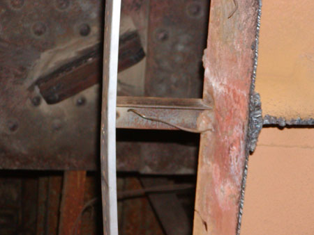 Figure 2
Angle iron channel sub-girt.
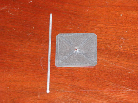 Figure 3
Insulation pin clip.
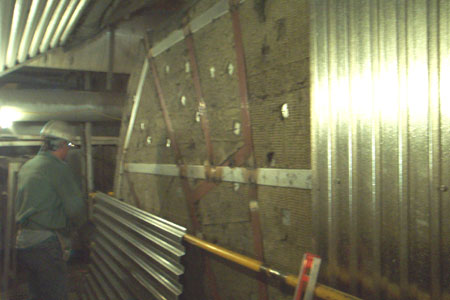 Figure 4
Lagging being installed without a high-temperature mat to prevent heat transfer.
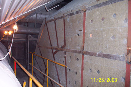 Figure 5
Sub-girt welded directly to stiffeners.
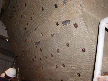 Figure 6
Plasterers lath chicken wire over insulation.
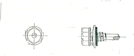 Figure 7
Lap tek sheet metal screw.
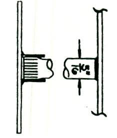 Figure 8
Knurled stud drive plate.
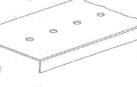 Figure 9
Channel sub-girt.
 Figure 10
Closure strips.