Boiler Island Equipment: Beyond the Steam-Generating Boiler
All steam-generating units or facilities are divided into two parts: the “boiler island” for steam generation and the “back end” or air quality control system (AQCS) area, where spent gases are cleaned and discharged into the atmosphere. Specially designed equipment is placed strategically around the boiler to use the hot gases carried by flues and the air carried by ducts to help the boiler be energy efficient.
On a fluidized bed boiler (circulating or bubbling bed*), for example, the flue gases leave the boiler and pass through a mechanical dust collector, economizer, and air heater on their way toward the back end and the stack. Figure 1 shows a typical flue and duct arrangement for a fluidized bed boiler.
Mechanical Dust Collector
Mechanical dust collectors are most commonly found on industrial-type steam-generating boilers (e.g., stoker-fired or hopper-bottom pulverized coal–fired). The mechanical dust collectors are perfectly suited for these types of boilers, which predominantly produce large dust and ash particles. The dust collectors collect these particles and re-inject them back into the furnace, helping improve boiler efficiency. A dust collector does not remove the finer/smaller dust particulates, which must be removed by precipitators or baghouses on the back end past the air heater to meet today’s emission requirements.
With the development of fluidized bed boilers, the mechanical dust collector again became an essential piece of equipment for boiler efficiency. Mechanical dust collectors, sometimes called cyclones, are located at the boiler gas outlet. A mechanical dust collector removes the larger size dust and ash particles from the flue gases leaving the fluidized bed boiler and feeds them back to the bed or fuel burning area.
How a mechanical dust collector works is quite simple (see view B-B on Figure 1). Dirty flue gases enter the top of the dust collector and “cyclone” around inside individual cylindrical tubes. Inside these cylindrical tubes, the cyclonic action of the flue gas and the centrifugal forces drive the larger dust particles out of the flue gas. These dust particles then fall down into a collecting hopper, where they will be collected and recirculated back into the boiler as bed material. The process of recirculating unburned particulates back into the boiler makes the dust collector an energy-saving and essential piece of equipment for a fluidized bed boiler.
Economizer
An economizer is a form of heat exchanger made of insulated tubes used to preheat the boiler feed water before it enters a steam drum or furnace wall circuitry. The economizer tubes are within either a tube wall enclosure or steel-cased walls. The most common economizer design is the bare tube in-line type, as shown in Figure 1. The tubes are horizontally placed in-line, or right on top of each other, to allow the flue gas to flow freely down around the tubes.
The use of economizers with steam-generating boilers goes back to the earliest boiler designs. The early boiler designers found that by adding tube banks near or at their boiler gas outlets, they could economically heat their water, save money, and reduce operating costs. Water enters at the bottom of the economizer tube bank and circulates up through the rows of tubes. Hot flue gases pass around the tubes, lowering the exit flue gas temperature and increasing the water temperature inside the economizer tubes.
Small, shop-assembled economizers were used on the early industrial boilers (e.g., stoker- or pulverized coal–fired boilers). The economizer tubes were housed inside a cased wall open at the top and bottom. These shop-assembled economizers were also insulated and either outer lagged or outer cased in the shop prior to being shipped to the plant.
As boilers increased in size and capacity, so too did the boilers’ exit gas temperature. The higher gas temperatures and larger widths across the boiler gas outlets made shop-assembled economizers unfeasible. Economizer tube banks then had to be field installed. For the fluidized bed boiler, the economizer is located after the dust collector and is normally insulated and lagged in the field. The thickness of the insulation required on the economizer casing is based on the temperature of the flue gas leaving the boiler gas outlet.
Air Heater
Air heaters are also a form of heat exchanger. They are used to heat cold air that will be used for combustion/burning of fuel using flue gases. This is by far the most common method of increasing boiler efficiency and energy savings. The two basic types of air heaters are the recuperative and the regenerative.
A recuperative air heater has no moving parts; heat is taken from the hot flue gas and transferred or exchanged to make cold air hot. The most common type of recuperative air heater is the “tubular” air heater, which has small-diameter tubes housed inside a casing box. The tubes are connected to a perforated plate at the top and bottom. Gas will flow through the tubes while air flows around the tubes. The size of the tubular air heater depends on the boiler operating conditions. The number of passes the air or gas makes is determined by the temperature of the air required at the burners and space/structural limitations. For example, there are multiple-gas-pass tubular air heaters with a single air pass and there are single-gas-pass tubular air heaters with multiple air passes. The insulation thicknesses for each air pass, regardless of type, is based on the temperature of the air leaving that air pass.
To calculate the air temperature on a three-air-pass tubular air heater as shown in Figure 1, a designer or engineer would need to know the air temperature entering and leaving the air heater and use the following formula:
Air Pass Number (1st pass, 2nd pass, or 3rd pass) x (total increase of air temperature) + (temperature of air entering air heater) (total number of air passes)
OR
1st pass x (420degF-150degF) + (150degF) =
240degF (3 air passes)
This type of air heater is most commonly used on industrial-type (e.g., refuse, wood, and biomass boilers) and fluidized bed-type boilers.
A regenerative air heater has moving parts, and the exchange of heat is done by exposing a metal heating surface to the hot flue gases and transferring/exchanging the heat to the cold air passing over the metal heating surface. The exchange of heat is done twice. First, hot flue gases exchange their heat to a metal surface, and then the metal surface exchanges its heat to the cold air entering the air heater. This type of air heater is most commonly used on utility boilers, where the gas and air temperatures are higher.
The two types of regenerative air heaters most commonly used in the power industry are the Ljungstrom and Rothemuhle. The Ljungstrom has a rotating heating surface, with the flue gases passing down through one side of the air heater as the cold air passes up through the other side. The Rothemuhle uses a fixed heating surface with a rotating housing. Flue gases come down into a hood and pass over the heating surface. Cold air enters the bottom of the heating surface housing and exits through an air duct in the hood housing. A regenerative air heater’s insulation thickness is based on the temperature of the flue gas entering the air heater.
Conclusion
The primary purpose of the boiler island equipment is to help the boiler make its steam or heat requirements. Without dust collectors, economizers, and air heaters, the boiler, especially a fluidized bed type, could not function properly. Any equipment or component, such as insulation, that saves energy also saves money at a rate important to any steam-generating unit.
*Circulating and bubbling fluidized bed boilers (CFB and BFB) are two types of fluidized bed boilers. A fluidized bed boiler uses a process by which solid fuels (i.e., coal) are suspended in an upward flowing gas or air stream at the bottom of the unit in which the burning fuel exists in a fluid-like state. The fuel is fed into the lower portion of the furnace area called the furnace bed. The bed area mixes the fuel with gas or air, and the mixture combusts.
References
The information contained in this article has been obtained primarily from public sources, without direct input from any of the boiler manufacturers.
Combustion Fossil Power, Combustion Engineering, Inc.,
4th Edition (1991).
Steam, its generation and use, Babcock & Wilcox Company,
40th Edition (1992).
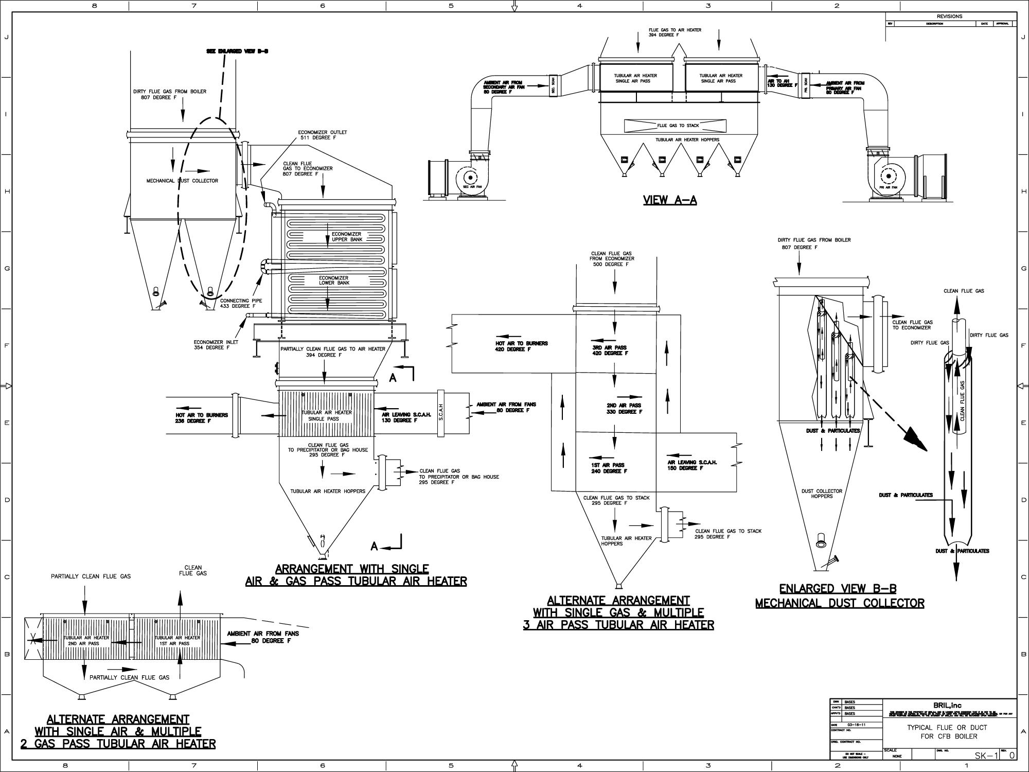 Figure 1