Case Study: Creating a Program for CUI Prevention at a Refinery
Introduction
This case study looks at a particular oil refinery located in the Midwest that has had a long-standing problem with corrosion under insulation (CUI). In the late summer of 2012, the refinery owner hired me as a consulting engineer to make practical recommendations to reduce the number of occurrences and severity of CUI. Unfortunately, no single insulation, jacketing, or coating will completely and permanently prevent CUI. While there are better and worse product choices for particular applications, the prevention of CUI requires that the facility owner follow a program that includes application of protective coatings prior to insulating, maintenance of the insulation systems, and timely repairs and/or replacement of materials when damage occurs to an insulation system.
In this particular facility, some of the operating units were more than 50 years old and had been using certain types of insulation since they were built. It was neither practical nor financially feasible for the owner to replace all the pipe and equipment insulation with a new type of material for the purposes of reducing CUI. Thus, in this particular case, I did not recommend using different insulation material—as I would have in other instances—that have water-inhibiting properties, such as perlite pipe and board; flexible aerogel blankets; and layered, rigid, glass fiber felt pipe and board. In this instance, the recommendations involved better use and care of insulation materials already in use at the refinery. Readers are encouraged to look at the specific design considerations for their system, industry standards and specifications, and manufacturer product recommendations before making a decision about insulation products for their unique systems.
Project Objectives and Methods
The objectives of the refinery owner were as follows:
- Receive recommendations on methods for minimizing occurrences and severity of CUI;
- Maintain as many existing materials, procedures, and practices as possible while reducing CUI;
- Minimize initial insulation costs and life-cycle costs;
- Maximize life of pipe, equipment, and insulation systems; and
- Enhance safety.
My objectives were to:
- Identify practices that should be continued;
- Identify practices that should be discontinued;
- Identify practices that should be changed; and
- Recommend new practices to minimize water intrusion into thermal insulation.
Background
While the refinery has been on this site over a century, the operating units were constructed more recently. Two units were constructed in late 1960s and early 1970s using asbestos-reinforced calcium silicate insulation with a 0.016″-thick aluminum jacket. Much of this older insulation system was still in place, and the utility owner had been inventorying and identifying both the asbestos-containing calcium silicate insulation and the asbestos-free calcium silicate insulation. The units constructed after the early 1970s were insulated with asbestos-free insulation consisting of calcium silicate in most places with the exception of pipe elbows, which were insulated with mineral wool. More recently, when new pipes were added or entire stretches of insulation had to be replaced, the utility had switched to using cellular glass for pipes with operating temperatures in a range from 250°F to 450°F, since cellular glass does not absorb water. In fact, the insulation contractor who had the maintenance contract was free to use calcium silicate down to 250°F, so there was a range from 250°F to 450°F where he could select either material.
Custom-fabricated removable/reusable blankets had been installed on many heat exchanger heads and valve bodies; however, the flange pairs were always left bare, a practice common at many oil refineries. Protective coatings had been installed in the last 10 years or so. Prior to that time, they were not consistently used on insulated pipe and equipment. The use of steam tracing on the pipe and equipment was extensive. However, in the last several years, the refinery owner had switched to adding electric heat trace on new pipe and equipment.
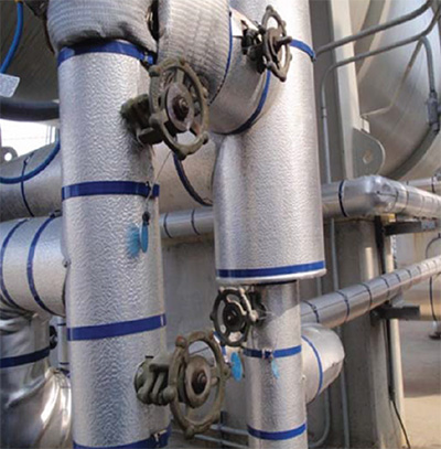
FIGURE 1: Pipes insulated with asbestos-free calcium silicate insulation, protected with aluminum jacketing. The blue banding indicates that the insulation is asbestos-free. Note the custom-made, wire-mesh covered removable/reusable insulation blankets in the top of the photo.
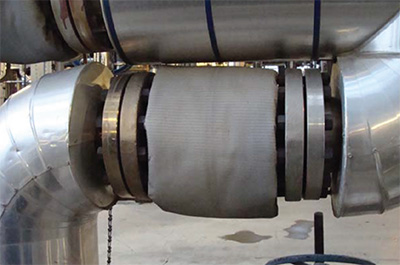
FIGURE 2: This photo shows a removable/reusable blanket, wrapped in wire mesh, on a flanged component. Note that the 2 flange pairs are bare, a common practice at this refinery and many others. This is done to prevent the accumulation of hydrocarbon liquids in the blankets, should a flange leak, since this could result in spontaneous combustion of those liquids when the blanket is removed.
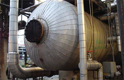
FIGURE 3: An insulated, horizontal vessel insulated with calcium silicate and aluminum jacketing. Note that the banding is not blue, indicating that either the calcium silicate contains asbestos, or the insulation has not yet been tested to determine asbestos content.
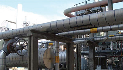
FIGURE 4: This photo shows pipes and vessels insulated with asbestos-free calcium silicate insulation and aluminum jacketing (marked with the blue bands). One valve insulated with a removable/reusable blanket can be seen in the left side of the photo. The insulation in this photo is generally in very good condition.
What Are the Problems?
There were a number of insulation system problems and challenges at this refinery.
- Pipe thinning due to CUI at certain locations (a pipe is only as strong as its weakest point).
- Limited budget for X-ray examination of pipes, and only smaller pipes could be done.
- Limited budget for insulation maintenance and replacement.
- Most older pipes and equipment were never coated for protection against CUI.
- Some pipes were insulated that may not have needed it (thus allowing for CUI).
Figures 5 through 11 illustrate the types of problems at this refinery. While much of the refinery insulation is in good condition, as shown in the previous photos, there are too many locations where rainwater obviously gets into the insulation and leads to CUI. If an inspector can visually see where rainwater gets into the insulation, then maintenance consisting of either repairs or replacement is the best solution to stop this situation from persisting. Furthermore, only insulation materials designed for outdoor use at the operating temperatures specified
should be used, even as temporary wrap insulation.
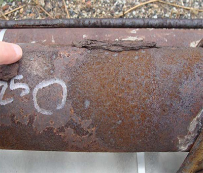
FIGURE 5: The CUI shown in this photo is particularly acute and destructive. This pipe was likely replaced and re-insulated after this photograph was taken.
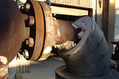
FIGURE 6: This photo shows partially disassembled mineral wool elbow insulation and aluminum jacketing. The disassembly was probably due to the proximity of the flange bolts, which required removal of some of the elbow insulation for their removal. Left in this condition, rainwater can enter the insulation, leading to wetting of the insulation and CUI over time.
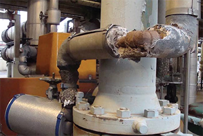
FIGURE 7: This deteriorated and missing elbow insulation looks as if it has been in this condition for a long time. Not only does this condition lead to CUI, but the heat loss from the elbow is very high. Furthermore, the exposed pipe insulation may be asbestos containing; if so, for health and safety reasons, it should not be left in this deteriorated condition.
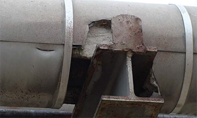
FIGURE 8: This photo shows a direct contact type of pipe support that allows rainwater intrusion, which wets the pipe insulation. Additionally, this design leads to high heat loss due to the direct contact between the pipe and the support. Given plain banding, this may even be asbestos-containing insulation, suggesting that this pipe support has been in this condition for a long time.
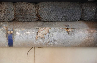
FIGURE 9: This photo shows pipes probably suffering from CUI. The pipe in the top is insulated with a woven textile material that is water absorbent. The pipe in the bottom is insulated with metal jacketed insulation; however, the jacketing has corroded, probably from the inside due to galvanic corrosion. This insulation and jacketing should have been replaced long ago.
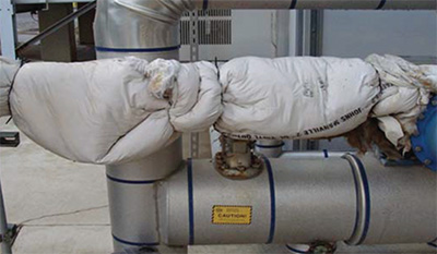
FIGURE 10: This photo shows the use of poorly applied temporary wrap insulation. The material appears to be fiberglass duct wrap with a vinyl facing. If so, the material is ill suited for use on outdoor applications at a refinery because it is designed for indoor use on surfaces with a maximum temperature of only 200°F. This temporary wrap should be replaced with either specified permanent insulation and jacketing, or specified removable/reusable insulation blanket(s).
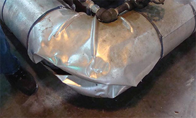
FIGURE 11: This photo shows an elbow with damaged insulation and jacketing—apparently damaged by foot traffic. There were a large number of these damaged elbows on horizontal, low-elevation pipes. The straight pipes were insulated with calcium-silicate insulation—a high compressive-resistance insulation—but the elbows were mostly insulated with a mineral-wool wrap, a low compressive-resistance insulation.
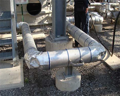
FIGURE 12: This photo shows straight pipes and elbows. The straight pipes are insulated with calcium silicate, and the elbows are insulated with mineral-wool wrap. Note that the straight pipe insulation has been able to withstand foot traffic abuse, whereas the elbow insulation has not.
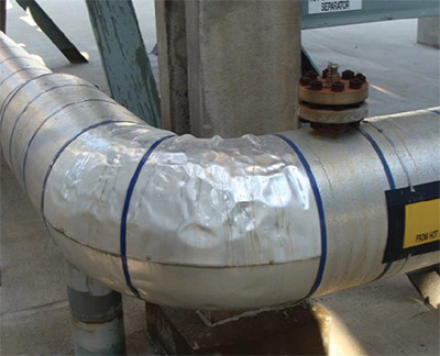
FIGURE 13: This photo shows an instance where the elbow was insulated with calcium silicate, which has been able to withstand the effects of foot-traffic abuse due to its high compressive resistance.
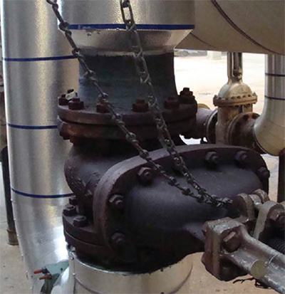
FIGURE 14: This insulation, on the top of the valve, has been installed to leave sufficient space for flange bolt removal, but he elbow insulation beneath this valve appears to be too close to the lower flange pair to allow for bolt removal. This elbow insulation might be damaged by mechanics when they remove this valve for servicing, allowing rain into the insulation, which, over time, may lead to CUI.
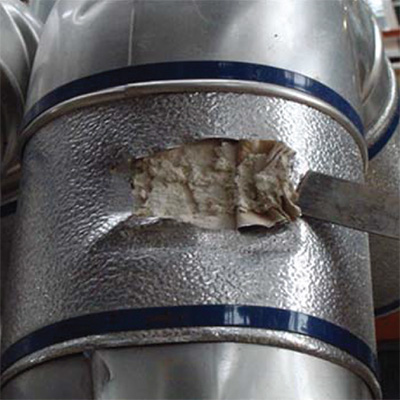
FIGURE 15: This photo shows where the aluminum jacketing has been gouged; this tear will allow rainwater to get into the pipe insulation and this, in turn, can lead to CUI.
Recommended Solutions for this Refinery’s Problems
Problem 1: Damaged or missing insulation such as shown in Figures 6 and 7.
Solution: Repair or replace with specified insulation materials so it looks like the insulation in Figure 1.
Problem 2: Damaged elbow insulation.
Solution: Use calcium silicate insulation on the elbows low enough to the ground to be stepped on, replacing the damaged mineral wool and metal jacket where that material has been damaged. See Figures 12 and 13 above.
Problem 3: Placement of insulation too close to flanges (as shown in Figure 6).
Solution: Leave sufficient space to allow for flange bolt removal (as shown in Figure 14).
Problem 4: Gaps and tears in the metal jacketing.
Solution: Either repair and replace the insulation or use metalized, pressure-sensitive tape to patch the metal jacketing, at least temporarily.
Problem 5: Missing metal jacketing (as shown in Figure 17).
Solution: Replace missing metal jacketing.
Problem 6: Missing or damaged insulation on frequently-maintained mechanical components.
Solution: Use removable/reusable insulation blankets on those components.
Problem 7: Pipe support designs that allow water intrusion.
Solution: Replace those, over time, with factory-insulated pipe supports.
Problem 8: Lack of protective coatings applied to pipe and equipment prior to insulating.
Solution: When the opportunity arises, remove corrosion from the affected pipe and equipment, and then apply protective coatings prior to insulating.
Problem 9: Broken seals that allow rainwater to enter insulation.
Solution: Repair broken seals or replace affected insulation, then apply a new seal.
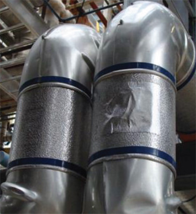
FIGURE 16: This photo shows how metalized tape has been used as a simple field repair to prevent rainwater intrusion. Such a repair, while not permanent, can be made quickly and inexpensively. Most importantly, it will be effective in preventing future rainwater intrusion.
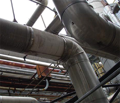
FIGURE 17: This photo shows a piece of missing metal jacketing. This should be replaced as soon as possible to prevent rainwater intrusion. If there are no resources to do this, the insulation can be wrapped by using some of the same metalized tape shown in Figure 16.
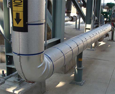
FIGURE 18: This photo shows how the pipe insulation system should look with all the metal jacketing in place. It is correctly installed to prevent rainwater intrusion.
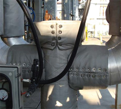
FIGURE 19: This photo shows the use of removable/reusable insulation blankets to cover a component that is frequently accessed for maintenance. These blankets have been designed, fabricated, and installed in such a way as to shed rainwater and allow easy removal; and then, after maintenance, reinstallation.
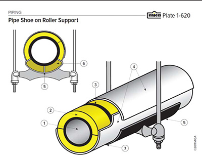
FIGURE 20: Plate 1-620 from the National Commercial and Industrial Insulation Standards (7th Edition) shows a design for a factory-insulated pipe support that can be installed in such a way as to prevent rainwater intrusion that can lead to CUI.
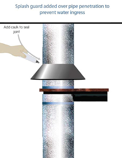
FIGURE 21: This image shows a graphic artist’s concept of a splash guard over a direct-contact pipe support. The splash guard, which can be fabricated by the insulation contractor or a fabricator from aluminum jacketing, can prevent most rainwater from getting into the exposed insulation.
General Recommendations
In addition to the solutions noted in the previous section, I made the following general recommendations to the refinery owner for the minimization of CUI in the conditions present at this facility. (Editor’s note: Unless specifically noted at the beginning of the article, the opinions and information shared by the author of any article in Insulation Outlook are those of the author and have not been confirmed by the NIA. The publication of an article does not constitute an endorsement of the author’s opinions.)
Recommendation 1: When installing new insulation, use cellular glass insulation for operating temperatures up to 350°F, and calcium silicate insulation for temperatures above 350°F.
Justification: Calcium silicate is highly water absorbent and very strong, thus it is abuse resistant. It performs adequately at high temperatures, and it contains a chemical inhibitor that helps prevent CUI when it does get wet. When used at operating temperatures above 350°F, its water-absorbing qualities will have little or no impact on CUI, since the water will completely boil away as vapor. Cellular glass, on the other hand, absorbs very little water, so when used at operating temperatures below 350°F, it should not promote CUI.
Since calcium silicate is a more durable insulation material, its use is preferred where the operating temperature prevents water absorption and retention.
Recommendation 2: Continue using aluminum jacketing, but only with a polysurlin moisture retarder instead of aluminum jacketing with a polykraft moisture retarder, as that type of retarder may not last as long.
Justification: The polysurlin moisture retarder is much more durable and prevents galvanic corrosion when the insulation becomes wet.
Recommendation 3: Use removable/reusable insulation blankets on components requiring frequent inspection or maintenance. These should be fabricated with silicone or polytetrafluoroethylene- (PTFE-) coated glass fiber fabric to prevent liquids from being absorbed.
The existing refinery specification for removable/reusable blankets is adequate. These blankets always should be reinstalled as soon as the mechanical maintenance activity that necessitated the insulation removal is completed.
Justification: These blankets allow inspectors and maintenance personnel to access components without destroying thermal insulation. The coated fabrics keep most rainwater and oil from getting into the insulation materials from which the blankets have been
fabricated.
Recommendation 4: When installing heat tracing on pipe, use only electric-resistance type.
Justification: The steam type can leak at fittings, introducing water to the insulation interior. Electric heat tracing is water and water vapor free, and makes it is easier to control temperature.
Recommendation 5: Seal damaged aluminum jacket with caulk or metalized, pressure-sensitive tape to prevent water intrusion.
Justification: Gaps need to be sealed to prevent rainwater intrusion.
Recommendation 6: Seal lap joints at 12 o’clock and metal jacket gaps with metalized, pressure-sensitive tape, or replace to prevent water intrusion.
Justification: Exposed joints and gaps need to be sealed to prevent rainwater intrusion.
Recommendation 7: Where the operating temperature allows, use protective coatings to protect steel surfaces from corrosion.
Justification: Protective coatings can effectively protect against CUI even if water does get into the insulation and onto the pipe or vessel surface.
Recommendation 8: Use only “temporary” insulation that is suitable for the operating conditions (i.e., does not hold water against steel surfaces and meets temperature requirements).
Justification: Many applications of “temporary” insulation wrap get left in place, becoming permanent. If they do not exclude rainwater and/or become deteriorated by weather and heat from the pipe, then they can absorb rainwater, which can lead to CUI.
FIGURE 22: New pipes that have had a protective coating applied prior to insulating. This protective coating will reduce the probability of the occurrence of CUI after these pipes are insulated.
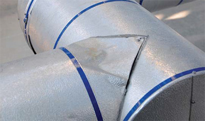
FIGURE 23: A broken seal where the metal jacket meets the metal jacket at a 90° junction can allow rainwater to enter the insulation, possibly leading to CUI. This seal was apparently broken by a worker stepping on the metal jacketing, deforming the metal in the process. This jacket either should be repaired or replaced with new metal jacketing and then sealed. A temporary repair might be to use metalized pressure-sensitive tape to seal gaps such as these.
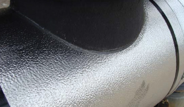
FIGURE 24: Here is a good quality continuous seal that prevents rainwater from penetrating the insulation covered by the jacketing.
Conclusions
CUI is a problem at many refineries. At the particular refinery in this case study, several recommendations could reduce the frequency and severity of CUI. Where applicable, those recommendations were to continue using the same insulation materials, but with more specific operating temperature recommendations and with a more specific aluminum jacketing recommendation. This includes continuing to use calcium silicate insulation at operating temperatures equal to and above 350°F, and cellular glass at operating temperatures below 350°F. Additionally, the
aluminum jacketing should have a polysurlin moisture retarder.
Recommendations also include performing regular maintenance such that damaged insulation is either repaired or replaced, following best practices. Where gaps or tears occur, repairs should either be made with sealant or using metalized, pressure-sensitive tape. Missing jacketing should be replaced as soon as possible. Rigid pipe insulation should be used on low-elevation pipe elbows to protect against foot traffic damage. When the opportunity arises, direct contact pipe supports and hangers should be replaced by those that are factory insulated. Removable/reusable blankets—at appropriate specification for the operating temperature—should be installed at components that are frequently inspected and/or repaired. Before new pipe or equipment insulation is installed, metal surfaces should first be covered with a protective coating on pipes with operating temperatures below the maximum use temperature of the protective coating.
While following these recommendations does incur some initial financial costs, choosing preventative measures will save money in the long run because they will reduce the frequency and severity of CUI and, in this case, reduce energy use for hydrocarbon fluid heating at the
refinery.