Cellular Glass on LNG Systems
Specifying LNG Insulation Systems
Due to the particular characteristics of liquefied natural gas (LNG) facilities, special care needs to be taken when working on insulation systems for LNG piping and equipment. The following are important design factors to consider when insulating LNG piping and equipment.
Water-Vapor Intrusion
Any insulation system for a below-ambient application must be designed to be vapor tight. This is particularly true for insulation systems for applications with cryogenic operating temperatures. Water intrusion into the system will degrade performance of the insulation system and can lead to other problems.
Ice Formation
Moisture intrusion and ice formation within the insulation system will reduce the system efficiency and increase operating costs. Ice formation can result from a failure in the insulation system or from insufficient insulation thickness; either way, ice adds weight. This added weight can lead to equipment damage if it exceeds the load capacities of supports or equipment.
Fire Risk
The risk of fire is always a concern for LNG facilities, particularly for off-shore platforms and floating production, storage, and off-loading (FPSO) vessels. The combustibility of the insulation system will be a consideration in these cases.
Pipe Load at Supports
Supports are critical since they need to be well insulated to prevent ice formation and need to be able to accommodate system movement as the system is put in service and the pipe contracts.
Dimensional Changes
Most of these LNG systems include long runs of piping. As will be discussed later, even a short section of LNG line will contract up to an inch when put in service. This contraction must be addressed in the design of the insulation system. It is important that the specifier address each of these factors in the design of the insulation system.
Cellular Glass Insulation for LNG Systems
Given the specific needs of LNG systems, cellular glass insulation can be a good option. There are 4 primary reasons cellular glass insulation can function well on an LNG system. Cellular glass insulation is a foam of sodium silicate glass and the cell walls of the glass foam are impermeable; this is important when considering the issue of water-vapor
intrusion into the system. Relative to density, cellular glass insulation has a high compressive strength. In addition, for applications that require high-load bearing materials, cellular glass insulation is available in a number of higher density, high-load bearing grades.
Cellular glass insulation is 100% glass. Since it does not burn, cellular glass insulation helps increase the fire resistance of the overall insulation system. As mentioned previously, the piping on an LNG system will contract when put in service. Since the coefficient of thermal expansion for cellular glass insulation is close to that of steel, the cellular
glass insulation will contract proportionally to the pipe and the differential between the 2 is easily addressed.
Uses of Cellular Glass in LNG Systems
Cellular glass insulation is primarily used in an LNG terminal on piping and equipment as well as on tank bases. Cellular glass insulation can also be found on the outer sidewalls of double-walled tanks as “corner protection.” Corner protection insulates the outer wall against a possible leak in the primary containment tank. Cellular glass insulation will
also sometimes be found in LNG spill containment pits to complement the pit’s fire-suppression systems.
Cellular Glass on the Tank Base
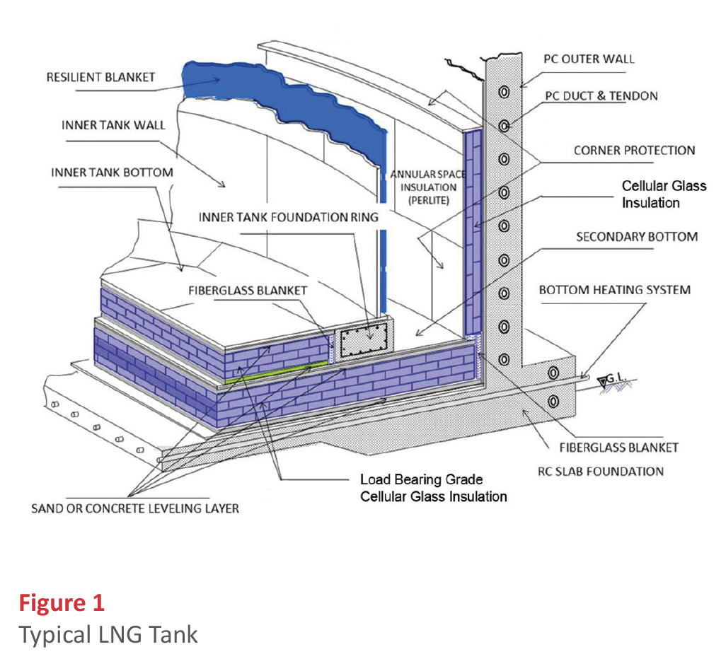
Before discussing cellular glass insulation for LNG piping, it is worth pointing out that about half of all the cellular glass insulation used on LNG applications around the world is used in LNG tank bases. Figure 1 shows a typical ground LNG storage tank. In this case the detail illustrates a “low” tank configuration.
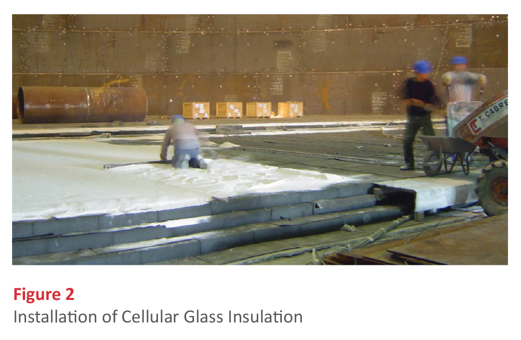
Low tanks have a higher footprint to height ratio than “high” tanks. In a high tank, the support ring would be in direct contact with the tank foundation. Figure 2 shows how the cellular glass insulation is installed as the base insulation as well as for corner protection. The corner protection insulates the outer tank wall against damage in the event of a
tank leak.
The typical design of a cellular glass insulation tank base is 3 layers of 8-inch thick load-bearing grade cellular glass insulation blocks with a bituminous membrane interleaving in between the insulation layers, as well as on the top and bottom of the insulation system. The specific grade or grades of cellular glass insulation used in the base will vary with the tank dimensions, seismic activity risk, and overall design of the base. After the final layer of insulation and capping is installed, a layer of fine sand is applied over the insulation system prior to installation of the base plates. The sand protects the insulation system as the base plates are welded in place.
Due to the fact that cellular glass is non-combustible, it is also sometimes used to complement the fire-suppression systems in LNG spill containment pits. Cellular glass insulation in cube form, contained in polyethylene bags, is installed at the bottom of a spill-containment pit. If a spill and subsequent fire occurs, the cellular glass insulation floats on the spill surface, the bags combust, and the cellular glass cubes are released. The insulation cubes then spread over the pool surface. This reduces the area exposed to flame, which reduces the thermal radiation and makes the fire easier to put out.
Cellular Glass as Pipe Insulation
When cellular glass insulation is used for LNG and other cryogenic pipe applications, the general approach is as follows:
- Double-layer construction;
- Inner layer joints dry: the inner layer of insulation is applied with the insulation joints unsealed;
- Outer layer joints sealed: the outer layer insulation joints are sealed and the joints of the outer layer are offset from the joints of the inner layer;
- Vapor retarder: a vapor retarder is applied over the insulation; and
- Metal jacket: finally, a metal jacket finish is applied.
Of course, there are variations to this approach. One of the most common is the use of a polymer coating in place of a metal jacket finish.
Typical Insulation Thickness
The typical thicknesses for cellular glass insulation on LNG piping ranges from 5½ inch to 8½ inch, depending upon pipe diameter and other design factors. Often the insulation thickness will be designed to limit heat gain to 8 or 9 BTU/hr•ft2.
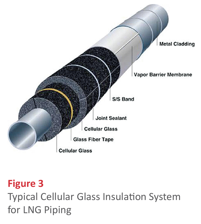
Figure 3 is a diagram of a typical cellular glass insulation system for LNG piping. Depending on pipe size, the cellular glass insulation is supplied in half sections or curved sidewall segments. Pipe diameter permitting, the first layer of pipe insulation is applied using glass-reinforced strapping tape for temporary securement. As previously mentioned, the joints of the inner layer are not sealed. The second or outer layer of insulation is applied with all insulation joints offset from the insulation joints of the inner layer. The joints of the outer layer are typically sealed to the full depth of the insulation thickness with a non-curing butyl-based sealant. The outer layer of insulation is secured with stainless steel bands. A vapor retarder jacketing, such as an aluminum/butyl wrap, is field applied over the insulation system. Finally a metal jacket finish is applied over all. When fire protection is part of the requirements of the insulation system, stainless steel jacketing is used.
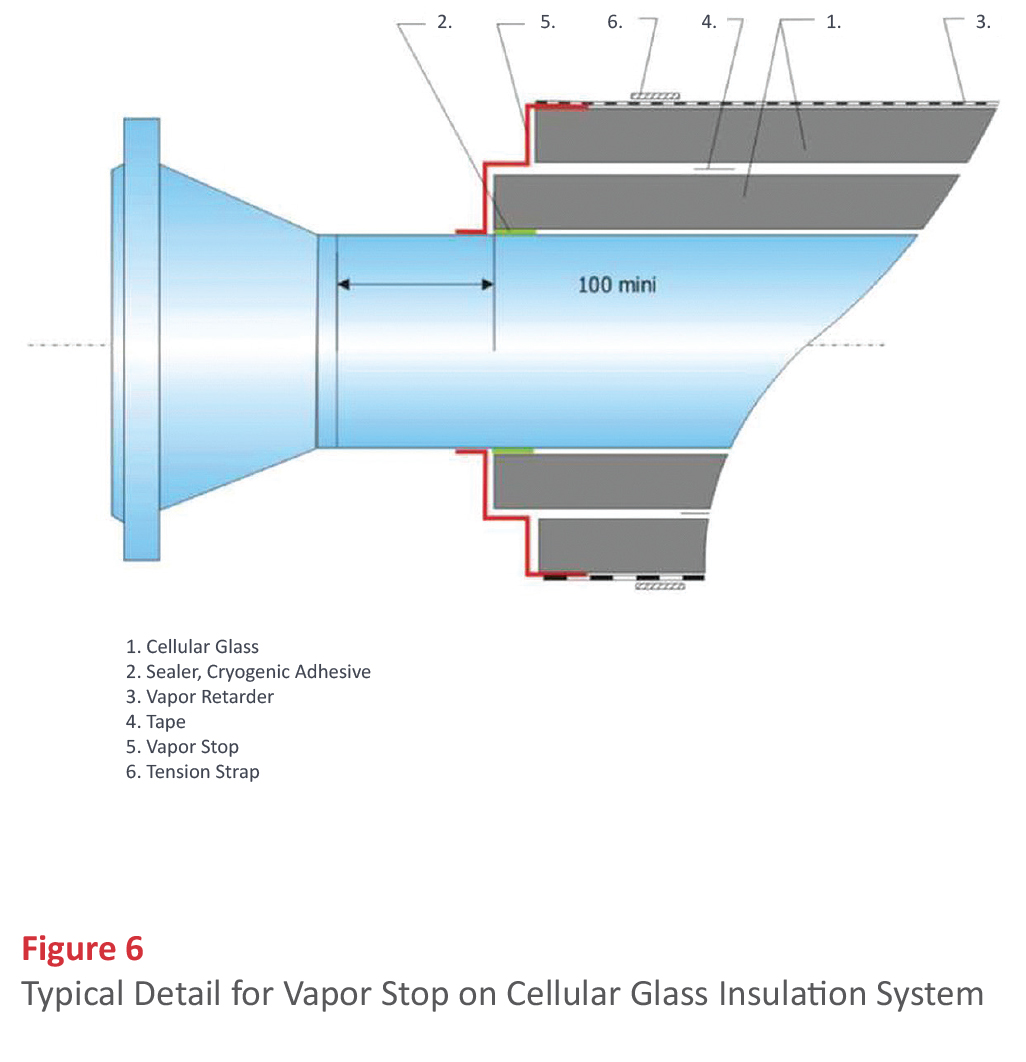
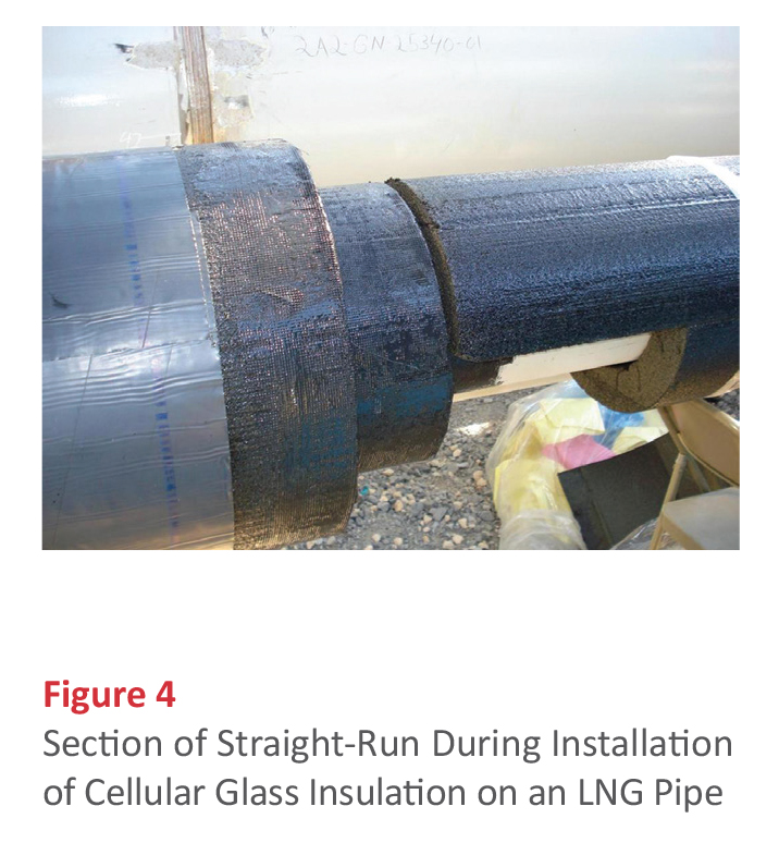
Figure 4 shows a section of straight-run during installation of a cellular glass insulation system on an LNG pipe. On this particular project, the specifications called for cellular glass insulation with the inside surface (the bore) and outside surface of both insulation layers to be coated with hot asphalt. This provides additional freeze/thaw damage protection to the surface cells of the cellular glass insulation. In this case, a modified bitumen membrane is being used as the vapor retarder.
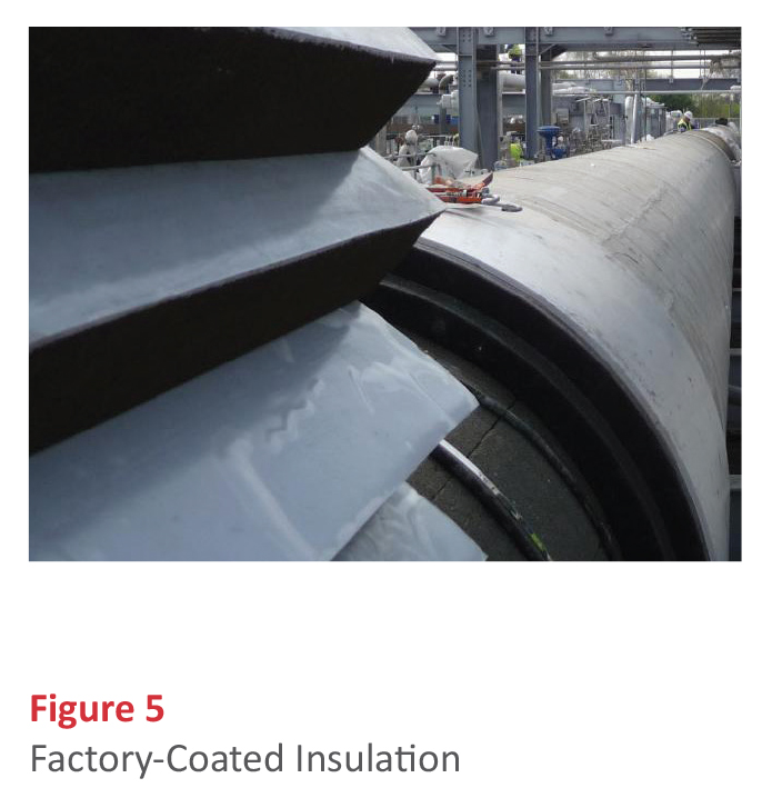
Cellular glass insulation may be supplied with the outer layer of insulation factory coated with a polymer coating, as shown in Figure 5. This polymer coating can serve as the vapor retarder as well as the final finish. When the diameter of the line is large enough, cellular glass insulation in the form of curved sidewall segments are supplied instead of half sections.
Vapor Stops
All insulation systems have interruptions. Vapor stops are used to isolate the insulation system at the interruptions to ensure any break in the insulation system that might occur at the critical area will not compromise the entire system. Vapor stops are recommended at all pipe supports, protrusions, and insulation terminations. Figure 6 shows a typical detail for a vapor stop on a cellular glass insulation system. The cellular glass inner layer is sealed to the pipe with a cryogenic adhesive/sealant and the inner layer is taped on. The vapor stop is applied to the pipe and overlaps the insulation. The vapor stop is constructed using cryogenic adhesive/sealant embedded with a glass fabric scrim reinforcing. The vapor retarder and metal jacket is applied over all.
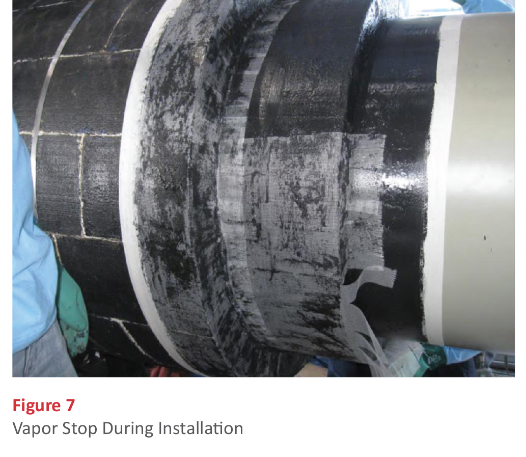
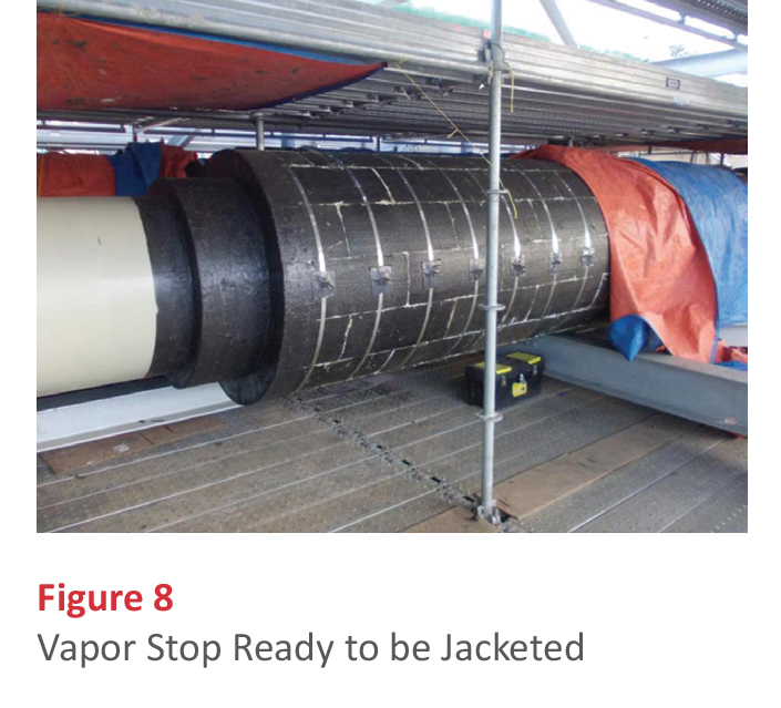
Figures 7 and 8, respectively, show a vapor stop during installation, and the completed detail ready to be jacketed. Note that the band fasteners have been taped to prevent puncture of the vapor retarder that will be installed.
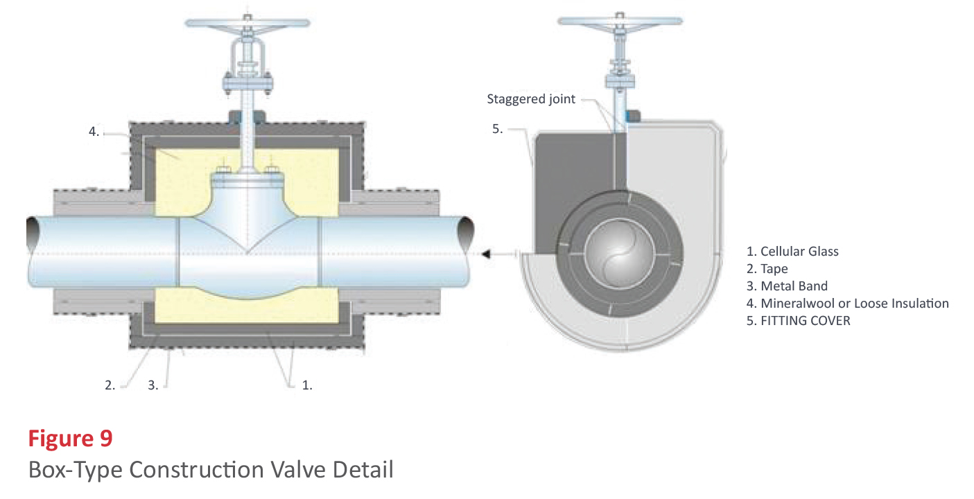
Fittings
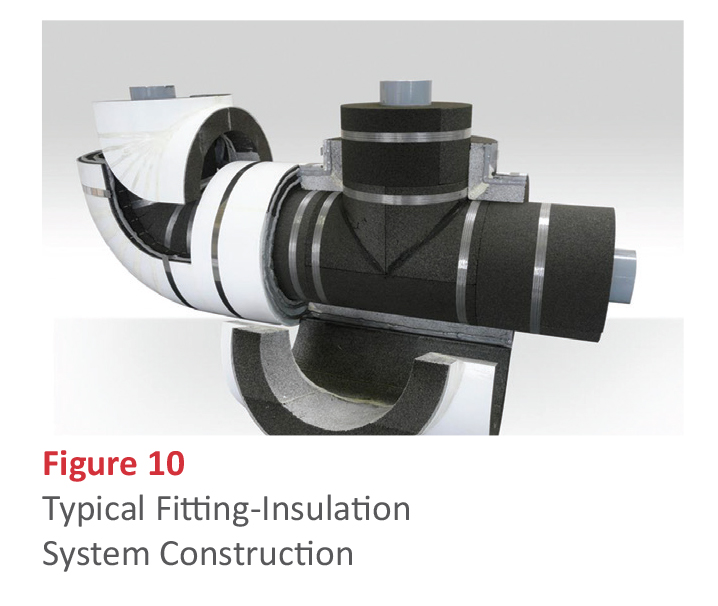
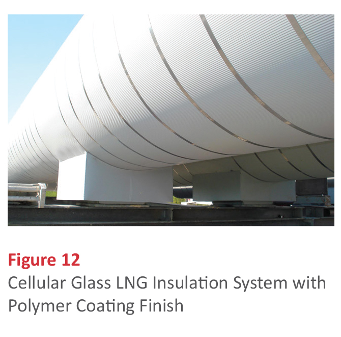
As with the straight-run piping, fittings are also required to be double-layer construction. This poses a challenge for the insulation fabricator when trying to achieve offset joint configuration. In some cases, box-type construction, as pictured in Figure 9, is used. This results in a void that is usually filled with inorganic loose fill insulation. Modern fabrication techniques have given rise to custom-fit valve covers that eliminate the void. These have become increasingly commonplace. Figure 10 shows a cut away model of the typical fitting-insulation system construction. Both a tee and an elbow are shown. Note that even in this case where the fabricator has gone the extra mile to minimize through joints in the system, there are some through joints that are unavoidable. In this example, the vapor retarder is a factory-applied polymer coating. This coating can be, and occasionally is, used as the exterior finish and no metal jacketing is applied. Figure 11 shows the completed view of some fitting covers on a cellular glass LNG insulation system. In this case, a painted metal finish has been used. The painted metal results in the increased emittance of a mastic finish while still providing the durability and mechanical protection of metal. The increased emittance aids condensation prevention. Figure 12 shows another view of some completed elbows finished with an aluminized flexible jacketing along with metal jacketed straight runs; the photo is of a cellular glass LNG insulation system with a polymer coating finish.

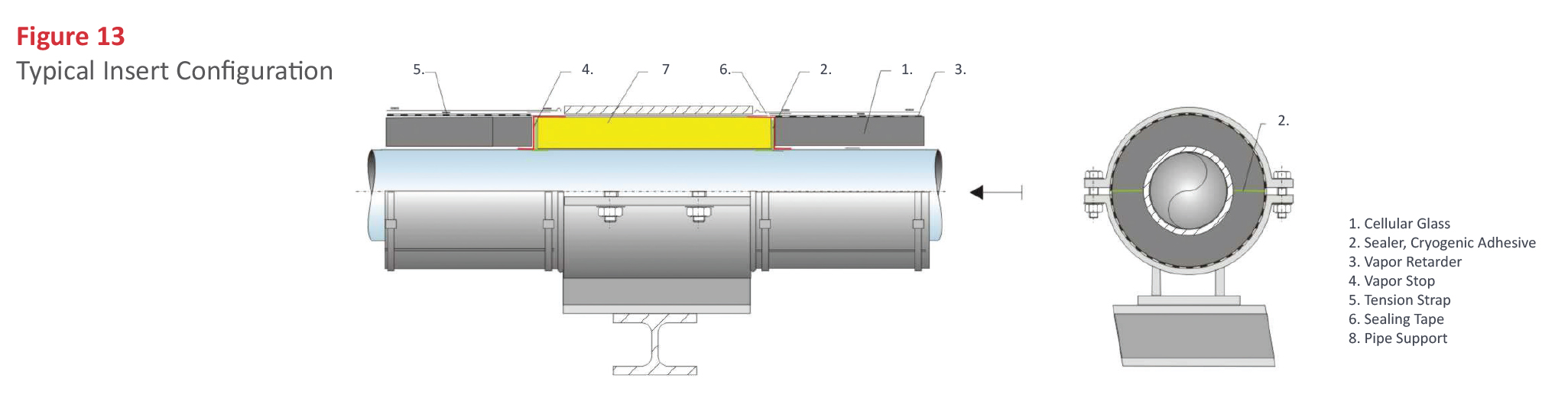
Pipe Supports
Pipe supports are another critical area on cryogenic pipe systems. Depending on the diameter of the line and support design, LNG lines may be supported directly on the cellular glass, on some type of insert, or directly on the pipe with a thermal break. Figure 13 shows the typical insert configuration with a high-density polyethylene (HDPE) insert as the load-bearing component. Another approach is the direct support. With a direct support, the pipe is supported directly on a pipe shoe. A thermal break such as a Micarta block is used to avoid a direct thermal short. Often the spacing of supports and the designed load allow the pipe to be supported directly on the cellular glass insulation system.
Contraction Joints
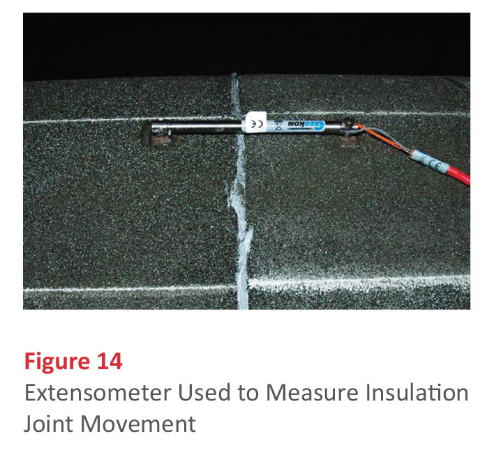
The amount of contraction for an LNG pipe can be close to 3¾ inch per 100 lineal feet. For a typical LNG system, the differential contraction between the pipe and cellular glass insulation is roughly 3 inches per 100 lineal feet. Since the standard cellular glass insulation contraction joint is designed to accommodate up to 1 inch of contraction per joint, roughly one contraction joint is used every 30 feet with this type of approach. The general design is a compressible insulation-filled gap in both insulation layers and a flexible vapor barrier material on the outer insulation layer. There is a question as to whether these joints are really needed in a cellular glass insulation system for LNG piping. In fact, numerous tests have been performed to determine if contraction joints in cellular glass insulation systems are needed, and if they actually work (see Figure 14 for the tool used to measure insulation joint movement). The results of an earlier study were published in the September 2001 issue of Insulation Outlook in an article entitled “Seal It” by Randolph W. Gerrish and Timothy Bovard. In this study, it was shown that cellular glass insulation systems installed on piping operating as low as -150°F do not need contraction joints. As far as cellular glass insulation systems on piping with lower operating temperatures, subsequent studies have shown that with straight-run horizontal cryogenic piping, the insulation joints in a cellular glass insulation system (which are present every 24 or 36 inches) are able to accommodate the contraction of the system. The most recent study used a liquid nitrogen test line that reached an operating temperature of -320°F. In this study, the following observations were made:
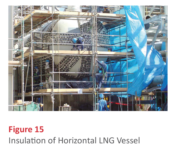
- Most contraction is easily absorbed between the sections of cellular glass insulation on horizontal straight piping, even when 36-inch long pipe insulation sections were used. (Figure 15 shows the insulation of a horizontal LNG vessel.) System tests showed that even when a traditional 1-inch contraction joint was installed, 80% of the movement was accounted for between the sections of individual pipe insulation and not at the contraction joint. According to tests performed in this study, contraction joints are not required on straight runs of piping insulated with cellular glass. The insulation must be installed with the ends of the insulation facing another flat surface. An example location for the removal of the contraction joint may include sections of pipeline insulation between pipe supports. Since the coefficient of expansion is slightly higher for the stainless steel than the cellular glass insulation, the insulation joints tighten during cooling and create a tightly-sealed insulated pipe system.
- Contraction joints are required in regions with a change of piping direction (e.g., elbows). When the piping contracts more than the cellular glass insulation, a point load will form between the metal and insulation interface. The point load may crack the cellular glass insulation fitting. If the distance between the change and direction and the support is greater than 20 feet, a contraction joint is recommended.
- Based on load requirements, vertical cellular glass pipe insulation must be supported at least every 50 feet. The expansion/contraction joints on vertical piping are installed, under the insulation support ring, under any pipe supports, and under the top elbow.
Thus, the particular design and characteristics of the system determine whether contraction joints are necessary.
Installing Cellular Glass
Cellular glass insulation for LNG vessels, exchangers, large diameter piping, and other equipment follow the same double-layer insulation approach. The primary difference is that the securement of the inner layer is done with stainless steel banding rather than temporary securement with filament tape. Instead of half-sections used on smaller diameter piping, the cellular glass insulation is supplied as curved sidewall segments, head segments, or special shapes, depending on the geometry involved. The outer layer of insulation is sometimes adhered using a low permeability, 2-component adhesive. In this case, the adhesive also serves as the joint sealant. As with the piping, a vapor barrier and metal jacket are installed over the insulation. Where fire protection is included as part of the expectations from the cellular glass insulation system, stainless steel is used as the outer jacketing.
Pre-insulation
Offsite or pre-insulation is becoming increasingly prevalent with LNG projects. In these cases, LNG modules are constructed off-site then shipped to the project site for final installation. This is done primarily to save labor costs, although in some cases the conditions at the actual project site are so severe that pre-insulated modules are the most practical approach. Figure 16 shows a completed module ready for transport.

LNG Projects with Cellular Glass Insulation
Cellular glass offers a combination of features that are useful in properly insulating LNG systems. With the right combination of design criteria and proper planning, it can be used to increase efficiency and lengthen the life of equipment in LNG systems.