Heat? Cold? Rain? No Problem!
Lagging is steel or aluminum finishing material used to cover many types of insulation, especially on large, flat surfaces such as boiler walls, flues, ducts, precipitators, bag houses, selective catalytic reduction systems, air heaters, economizers, scrubbers, wind boxes and fans. Also known as cladding or sheet metal, lagging does not include a vapor barrier, and ranges in thickness from 0.032 inches to 0.063 inches for aluminum, and from 20 gauge to 16 gauge for steel. Lagging, in general terms, is a tailored job of covering the insulated areas to suit the particular installation and its configurations.
What is the purpose of lagging? First and foremost, it is used to protect the insulation it covers and is applied over insulated areas to present a true plane – a flat and even surface. It must be stiffened and fastened on adequate centers to prevent excessive deflection or "oil canning" when hot or cold.
Secondly, lagging is used to provide a weatherproof construction complete with proper flashings, slopes and seals to ensure water runoff without the possibility of ponding or accumulation of water. You might think that this only applies to outdoor installations, but it can also be a problem in indoor installations where companies water-wash their steam-generating boilers and equipment. Water is the enemy of any insulation system, regardless of how it gets there.
Material Specifications
There are three standard types of metals used for lagging: galvanized steel, stainless steel and aluminum.
- Galvanized Steel* – Galvanized steel lagging is available plain or treated for painting. It can either be a ribbed or flat sheet material and should be specified as being a commercial-quality material and conform to ASTM specifications A924 with a commercial zinc coating of at least 0.90 ounces per square foot.
*Galvanized is a term long used to describe steel sheets coated with zinc. A galvanized lagging sheet has a shiny-flaked look while the treated-for-painting galvanized lagging will either have a dull weathered appearance or actually be painted with a primer coat.
- Stainless Steel – Stainless steel lagging is normally provided in type 304 but can be provided in other types. The outside exposed surface of the stainless steel lagging should have a 2B finish. The temper of the stainless steel material should bend in half or back on itself without cracking.
- Aluminum – Aluminum lagging is usually provided with a stucco-embossed finish. The core material for the aluminum lagging must conform to ASTM Specification B209 and have a cladding of 7072. Ribbed aluminum lagging must have a temper of H 174, and flat aluminum lagging must have a temper of H 154.
Environmental Concerns
As with any product, particular precautions must be taken in the handling and storage of aluminum or steel lagging materials. The finish on both materials is susceptible to atmospheric contamination. It is advisable to take the following precautions:
1. Store the material inside.
2. Elevate the material above the ground or floor to allow air circulation.
3. Always place ribbed sheets, flat sheets or coiled material on end or edge to allow water or moisture to drain.
4. Material should not be tightly sealed with covers such as plastic. This tends to create a sweating condition that will produce oxide damage. Some ventilation is necessary.
Special attention must be given to coastal projects. It has been found that on coastal jobs, contamination and discoloration can occur from atmospheric condensation between sheets when they are laid flat. You should carry out routine inspections. Sheets should be separated and ventilated if any condensation is found.
Also, where aluminum lagging comes in direct contact with another type of metal such as steel, it is necessary to paint all of these other surfaces with a heat-resistant aluminum paint that has a temperature service limit of up to 350 F. This will prevent galvanic action between the aluminum and the steel.
Structural Concerns
All lagging is attached to a support or structural system by the use of sheet metal screws. A sheet metal screw should be applied on every other rib, regardless of the material involved. On flat sheets, sheet metal screws should be applied on a maximum of 2-foot vertical by 3-foot horizontal centers. Common sense should prevail in the use of screws. Excessive numbers are costly and detract from appearance. The lagging screws are installed properly when they are pulled down tight. A screw is considered loose when you can wiggle the washer with your fingertips.
It is also important to take into consideration the weight of lagging, which is required for calculating structural steel design. Lagging weight is also a consideration in crane sizing for lifting pieces of equipment (i.e., flues, ducts, selective catalytic reactors) to elevation if you intend to ground-install the lagging to the equipment prior to lifting. See the chart below for approximate weights of standard lagging material thickness.
Expansion and Contraction
Expansion and contraction requirements represent a major problem in lagging. Necessary provisions for expansion and contraction must be provided in the lagging design to maintain a neat and proper design when in service. When the lagging is properly installed over insulated areas, it presents a true plane, stiffened and fastened on adequate centers to prevent excessive deflection or "oil canning" when hot (expansion) or cold (contraction).
Expansion and contraction are a function of temperature. As the temperature of the surface (i.e., flue plate) to be insulated and lagged goes up, so does the amount of expansion and contraction that must be incorporated into the lagging system. The higher the temperature, the more attention must be made to the lagging system. This is especially true when a Selective Catalytic Reduction (SCR) system is installed at a power plant to help reduce the plant’s NOx emissions. The SCR system is usually installed between the boiler gas outlet and the air heater. Under normal operation, an SCR system operates with gas temperatures between 600 and 700 F.
Lagging expansion and contraction are absorbed by any combination of the following, with each part carrying some portion of the expansion and/or contraction:
- The lagging support system.
- The ribs of the box rib-type lagging because they will allow the lagging to move with the contraction and expansion of the surface being covered.
- The standing seam between flat lagging sheets.
- The flashing.
The expansion or contraction is done through the lagging support system being used (i.e., sub-girt, angle iron, stud, pin, Z support or H support system). It is their ability to bend, expand or contract that will contribute to the expansion and contraction of the lagging system.
When using either sub-girt, Z or H-type support systems, it is recommended to use short spans with a maximum of 10-foot lengths wherever possible. This allows the expansion and contraction to be taken within each short support assembly. Small gaps must be left between the short spans of the sub-girt, Z or H assembly equal to the amount of expansion expected in that particular direction. This small gap can be anywhere from an 1/8-inch to a 1/2-inch wide. In no case should the short sections of the sub-girt, Z or H assembly be welded together as this will inhibit the expansion and/or contraction of the lagging.
Use an "S" lap* on the vertical seams of the lagging for hot systems (surfaces above 350 F) such as SCR flue systems, which normally have long vertical walls and a large amount of side-to-side expansion. If the lagging is applied when the unit is not running (referred to as being "cold"), then the straight edge would be jammed completely into the "S" lap. If the lagging is being installed while the unit is running (referred to as being "hot"), then the flat edge would only be partially placed into the "S" lap, leaving a gap or room between the flat edge and the back of the "S" lap. This gap will normally be about an 1/8-inch to a 1/4-inch, depending on the amount of expansion the entire SCR is designed to move from side to side. This gap will allow the lagging to contract back when the unit is shut down and would prevent "oil canning" or buckling of the lagging. The use of an "S" lap would also eliminate the need of stitch screwing of the lagging panels together at the lagging seams. This would also save money and time. Screws are required every 6 to 12 inches.
*An "S" lap looks a little like a Pittsburgh lap. It is formed on a machine on one side of the outer long edge of a rib sheet. (This is best done at a mill or shop.) The other side of the rib sheet is kept straight without any bent edge, as is normally done on a conventional rib sheet. The flat edge side of the ribbed lagging panel would then be placed into the "S" lap of the adjacent lagging panel.
Use an H flashing on the horizontal seams of the lagging for hot systems (surfaces above 350 F) such as SCR flue systems, which normally have long vertical walls and a large amount of top-to-bottom expansion. The H lap should only be screwed to the top sheet. This will allow the bottom sheet to expand or contract within the H flashing.
Surfaces 350 F and below are considered cold systems. The expansion or contraction of a cold system is not as great and, therefore, the lagging can be attached directly to the external stiffeners. This can be done as long as the stiffener spacing meets the required wind loading.
Flat Sheet Versus Box Rib
It is recommended that rib lagging should always be used wherever possible in lieu of flat sheet lagging because it helps in the expansion and contraction of the lagging system. Flat sheet lagging, in most cases, should be used for flashing, round surfaces, elliptical or irregular surfaces such as drumheads, or areas where space prohibits the use of rib lagging.
Here are some reasons for using a rib lagging versus a flat lagging:
1. The ribs or boxes of the rib lagging will aid in the expansion and contraction of the lagging system. A manufactured standing seam is required for flat sheet and is more labor-intensive than using a rib-type lagging.
2. Rib lagging is much easier to work with when covering large flat areas. The ribs help to give the material strength and rigidity, which is especially helpful on top surfaces where foot traffic may occur. On top surfaces that are exposed to the weather, rib lagging, if installed correctly, will help prevent water from ponding, or sitting. Ponding water on any lagging surface (rib or flat) will eventually penetrate the lagging system and damage the insulation underneath.
3. The problem of foiling occurs when the flat lagging is too thin or insufficient in rigidity for the application. Crinkling can occur when pressure is applied to the lagging during installation, for example, in screw locations. Depending on the surface area of application, this can be quite pronounced. This crinkling on the surface of the lagging looks like reused aluminum foil.
4. Rib lagging is nicer to look at on large flat or round areas than flat sheet. The ribs help break up the surface areas and present a more aesthetically pleasing view, especially from a distance.
5. Rib lagging can be cut or manufactured to any desirable length (up to 20 feet or longer). Flat lagging comes in either a coil or individual sheets manufactured up to only 10 feet long.
6. Flat lagging can bend easier than rib lagging due to the temper of the metals.
7. The pitch of the lagging on top surfaces exposed to the weather should be sloped for drainage at a minimum of a 1/4-inch per foot.
8. All hanger rods, pipes or other items penetrating the lagging should be provided with cover plates, boot, hoods or flashing made from the same type of metal as the lagging. This will prevent water from penetrating into the insulation and ensure that none of the insulation is visible. Provisions should always be made for any relative movement between the lagging and the penetration.
General Application Techniques
In most cases, erection of lagging follows the sequencing of applied insulation. On outside jobs, it is imperative that the insulation be covered at the earliest possible time, considering present-day insulation materials and techniques (only one or two days behind the insulator).
Generally, the success or failure of a lagging job depends on the basic setup of the job, the soundness of the preparatory work, and the ability of the shop crew to keep material flowing to the erecting crews. Under normal job conditions, a shop crew of two men can keep material flowing for two to three application crews. On the larger contracts, the shop forces must be increased according to the number of installation crews to ensure a completely efficient operation.
Unfortunately, many in the industry are having all of their corner flashing cut and broken into standard 6-inch by 6-inch corners offsite and sent to the job. This means the flat corner flashing will not be custom-fit at the corners at the job. This is not good lagging technique. A prefab corner flashing has the potential to overlap too far over the adjacent high rib and looks aesthetically displeasing. It could also allow water to sit or pond on the top surface areas of the lagging, where there is a trough between the high ribs. The trough is created when the excess overhang of the prefab corner flashing opens a long vertical space between the ribs.
Conclusion
Installing lagging means installing a tailored job for the purpose of covering the insulated areas to suit the particular installation, its configurations, and for aesthetics. You cannot separate the importance of lagging from insulation. Each part of insulation and lagging must work together to ensure a proper working system. Good lagging practices must be enforced in the design of the system and at the job site. Pay attention to all aspects of your insulation and lagging system, and remember that while lagging may be the last thing you do, it should be the first thing you think about when designing and installing an insulation system.
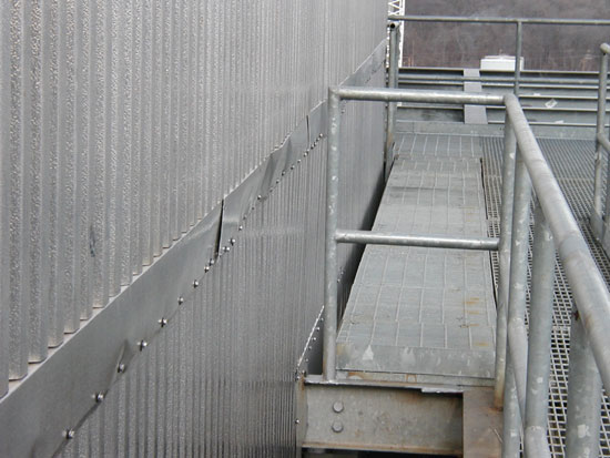 Figure 1
Buckled lagging flashing on a Selective Catalytic Reducation System sidewall.
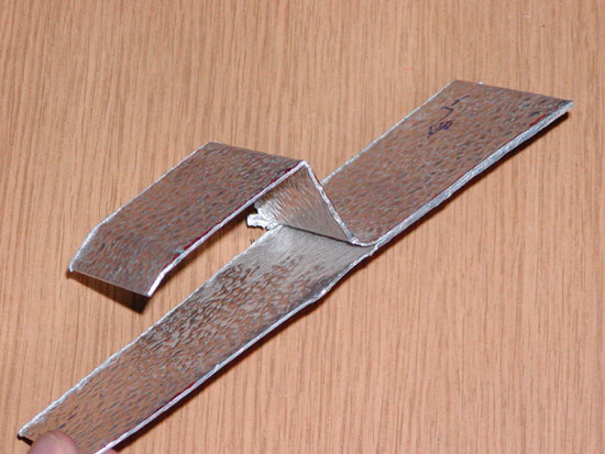 Figure 2
H flashing.
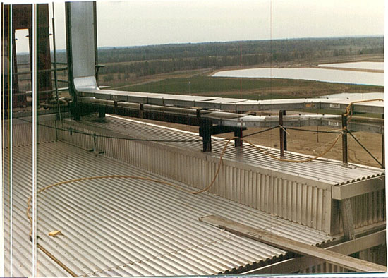 Figure 3
Penetrations through lagging.
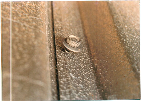 Figure 4
An example of a sheet metal screw that is not screwed down tightly.
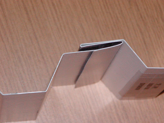 Figure 5
“S” lap flashing.
 Figure 6
Typical lagging flashing at roof cans.
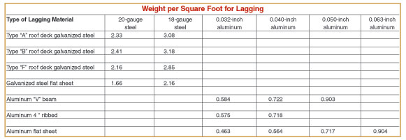 Figure 7
Weight per square foot for lagging.