Mechanical Insulation Simple Calculators: A Guide to the Energy and Condensation Control Calculators
As a part of efforts by the Department of Energy’s
Advanced Manufacturing Office to improve the energy efficiency of the U.S.
industrial and commercial sectors, the National Insulation Association (NIA)
and its alliance partners worked together to design, implement, and execute the
Mechanical Insulation Education & Awareness Campaign (MIC).
MIC is a program to increase
awareness of the energy efficiency, emission reduction, economic stimulus, and
other benefits of mechanical insulation in the industrial and commercial
markets. An integral component was the development of a series of “Simple
Calculators.” The calculators provide the user instantaneous information on a
variety of mechanical insulation applications in the industrial, manufacturing,
and commercial markets. Topics include:
- Condensation Control for Horizontal Pipe
- Energy Loss, Emission Reduction, Surface
Temperature, and Annual Return (two calculators:
one for Equipment, and one for Piping) - Financial Returns/Considerations
- Estimate Time to Freezing for Water in an
Insulated Pipe - Personnel Protection for Horizontal Piping
- Temperature Drop for Air in an Insulated Duct
or Fluid in an Insulated Pipe
The calculators are online at
the National Institute of Building Sciences’ Mechanical Insulation Design Guide
(MIDG) website, www.wbdg.org/midg, and can be accessed from the NIA
website, www.insulation.org. They are fast, free, and functional tools
that make it easy to discover energy savings, financial returns, as well as
other information used in the design of mechanical insulation systems for
above- or below-ambient applications.
This article, including text excerpted from the MIDG website, provides
an overview and guide to use of the calculators for energy and condensation
control for horizontal piping.
Energy Calculator for Horizontal Piping
As an aid to understanding the relationships
between energy, economics, and emissions for insulated systems for horizontal
pipe applications, a simple spreadsheet calculator was developed. A similar
calculator for equipment, vertical flat surfaces, also was developed.
The algorithms used in the
energy calculators are based on the calculation methodologies outlined in ASTM C680-10 – Standard Practice for Estimate of the
Heat Gain or Loss and the Surface Temperatures of Insulated Flat, Cylindrical,
and Spherical Systems by Use of Computer Programs.
The pipe calculator estimates
the heat flows through horizontal piping assuming one-dimensional, steady-state
heat transfer. Information concerning a hypothetical insulation system (e.g.,
the length of run, pipe size, operating temperature, ambient temperature and
wind speed, insulation material, and surface emittance of a proposed insulation
system) may be input by the user. Calculated results are displayed for a range
of insulation types and thicknesses, and include surface temperature, heat
flow, annual cost of fuel, installed cost, payback period, annualized rate of
return, and annual CO2 emissions.
Other geometries and more
complex insulation systems may be analyzed using publicly available software
such as the 3E Plus® Insulation Thickness Computer Program. 3E Plus
was developed by the North American Insulation Manufacturers Association and is
available at www.pipeinsulation.org.
The Energy Calculator for Horizontal Piping requires “Input Information” for thirteen variables (see
Figure 1). Results are updated as each
input variable is entered. Below are instructions and additional information
for each input variable. Sample inputs appear in a box, after each instruction.
- Line 1. Enter the length of the piping run in linear feet 1
The default value
is 1 linear foot, but you may enter any length of piping run. The initial
“Results” section contains installed cost for the default footage (1 linear
foot) for the nominal pipe size and material selected in lines 2 and 6,
respectively. You may find it helpful to review the cost information for 1
linear foot before completing line 1 and line 7, the cost multiplier. - Line 2. Select Nominal Pipe Size, NPS 3
The default value
is an NPS of 3″. Using the drop-down box, however, you can select any pipe size
from 0.5″ to 14″. Above 14″, we suggest you refer to the 3E Plus program or
take another approach. - Line 3. Enter average operating (process) temperature for the period of
operation 350Enter the average
below- or above-ambient operating temperature in degrees Fahrenheit (°F) - Line 4. Enter average ambient temperature for the period of operation
75Enter the average
ambient temperature in °F - Line 5. Enter average wind speed for the period of operation (if
unknown, use 1 miles per hour for indoor, 8 mph for outdoor) 8Enter the average
wind speed in mph. If unknown, it is suggested you use 1 mph for indoor and 8
mph for outdoor applications. - Line 6. Select an insulation material. Note: Calculator does not screen
for material temperature limitations-Use caution. Mineral Wool (0°F to
1,200°F)The default material is
mineral wool; however, you may use the drop-down box to select one of six insulation
materials:- Calcium Silicate (80°F to 1,200°F)
- Cellular Glass (-450°F to 800°F)
- Elastomeric (297°F to 220°F)
- Fiberglass (0°F to 850°F)
- Mineral Wool (0°F to 1,200°F)
- Polyisocyanurate (297°F to 300°F)
You
will note that each of the material options contains a general operating
temperature range.Should you
wish to use a material that is not listed, you will need to refer to the 3E
Plus program. The simple calculators do not have the capability of utilizing
user-supplied thermal curves. Thermal conductivity values for the listed
materials are based on ASTM material specification values. - Line 7. Enter a cost multiplier to modify the default installed costs
(e.g., enter 1.10 to increase costs 10%) 1.00As noted under line
1, the calculator contains default costs for each type of material and pipe
size. If you enter 1 linear foot in line 1, select the size pipe in line 2, and
the insulation material in line 6, you can review the default cost for a linear
foot for various insulation thicknesses in the “Results” section. If “NA”
appears for a given insulation thickness, that indicates that the thickness is
normally not available for the selected material. You can adjust the cost up or
down by simply modifying the multiplier. Enter 1.10 if your cost is 10% higher.
Enter .80 if your cost is 20% lower.The installed
costs were developed from industry sources and represent single-layer
installations. They include aluminum jacketing, but do not include vapor
retarders or vapor sealing. They may be viewed as higher than actual, but that
view will vary greatly depending upon labor cost, operating conditions,
insulation system, and a variety of other factors. Understanding that those
variances exist is the reason the multiplier approach was selected. - Line 8. Enter the effective emittance of the exterior surface (see
MIDG>Design Data>Table 1 for guidance) 0.10-Aluminum, oxided, in
serviceA definition of emittance
is often requested. Technically, emittance is defined as the ratio of the
radiant flux emitted by a specimen to that emitted by a blackbody at the same
temperature and under the same conditions. In simpler terms: the darker the
surface, the more radiant heat is absorbed. The default value is 0.10, which
represents aluminum that has oxided in service. However, using the drop-down
box, you can select the typical emittance value for eleven of the commonly used
insulation jacket finishes. - Line 9. Enter the expected life of the insulation system in years 20.0
This value is the
economic life used for financial return calculations. The default value is 20
years. You can enter any number of years. - Line 10. Enter the number of hours per year of system operation (e.g.,
8,760 for full year operation) 8320Some systems may
not operate 24/7/365. You can input the estimated number of operational hours
anticipated. - Line 11. Enter the conversion efficiency of the system in percent 80
If you do not know the
conversion efficiency for the energy source, you can use the following typical
conversion efficiencies for various systems:- Fossil Fuel Boilers (Non-condensing) 65-85%
- Fossil Fuel Boilers (Condensing) 80-95%
- Electric Resistance Boilers 92-96%
- Electrically Operated Chillers 300-700%
- Absorption Chillers 60-100%
- Line 12. Select the fuel used Natural Gas
Using the drop-down box, you can select one of
five types of fuel: Natural Gas, Oil, Propane, Coal, or Electricity. - Line 13. Enter cost of fuel if known or use default value 8.00
A typical default
cost for each of the fuel types is provided ($/Mcf). You have the option of
simply entering your actual cost, if known, or accepting the default cost.
Based upon the input
information you entered, the “Results” section provides detailed information
for various insulation thicknesses. An example using the default values for all
input variables is shown in Figure 2 on page 27.
Condensation Control Calculator-Horizontal Pipe
This calculator estimates the thickness of
insulation required to avoid condensation on the outer surface of an insulated
horizontal steel pipe. Input data includes the operating temperature, the
ambient conditions (temperature, relative humidity, and wind speed), and
details about the insulation system (material and jacketing).
The insulation materials included in this calculator were selected to be
representative of some of the materials commonly used in the industry. The list
is not exhaustive, and other materials are available. Also note that some
materials are not available in all of the sizes and thicknesses covered by
these calculators, and some are available in sizes and thicknesses not listed.
Thermal conductivity data for the materials included in the calculator were
taken from the appropriate ASTM material specification. Figure 3 identifies the
ASTM specification and the material type and/or grade used in the calculator.
The calculator requires “Input
Information” for seven variables. Here are instructions for each data field and
additional information for each. As before, sample inputs appear in a box after
each step.
- Line 1. Select Pipe Size, NPS 4
The default value is an NPS of 4″, but by using
the drop-down box, you can select any pipe size from 0.5″ to 24″. - Line 2. Enter average operating (process) temperature, °F 40
The default value
is 40°F, but other values may be entered. - Line 3. Enter average temperature of the air surrounding the pipe 80
The default value
is 80°F; however, you should enter the average surrounding or ambient operating
temperature, in Fahrenheit, for the area in question. - Line 4. Enter relative humidity of
the ambient air 80The default value
is 80%. You should enter the specific design relative humidity for your
application, however. From a design perspective, it is better to use a
reasonably higher-than-average or worst-case value. - Line 5. Enter the wind speed of the ambient air (if unknown, use 0 mph
for worst-case conditions) 0As noted, when in
doubt, use 0 mph, which represents the worst-case conditions. - Line 6. Select an insulation material Cellular Glass
You may use the drop-down box to select one of
seven insulation materials: Cellular Glass, Elastomeric, Fiberglass, Mineral
Wool, Polyethylene, Polyisocyanurate, or Polystyrene. Should you wish to use a
different material than one of the ones listed, you will need to refer to the
3E Plus program. Thermal conductivity values for the listed materials are based
on ASTM material specification values. - Line 7. Select the effective emittance of the exterior surface 0.90-All
Service JacketAs with the energy
calculator for horizontal piping, a definition of emittance is often requested.
In simple terms, the darker the surface, the more radiant heat is absorbed. The
default value is 0.90, which represents All Service Jacket; however, using the
drop-down box, you can select the typical emittance value for eleven commonly
used insulation jacket finishes.
The “Results” section
highlights the thickness of insulation required to avoid condensation on the
outer surface of the insulation jacket. This thickness yields an average
surface temperature that is greater than the dew-point temperature plus a
safety factor of ¾°F. It should be noted that for some high-humidity
conditions, regardless of the insulation type or thickness, it is impossible to
avoid condensation on the outer surface. An example using the default values for
all input variables is shown in Figure 4.
Summary
The Simple Calculators are intended to provide the
user with online, at-your-fingertips, snapshot information to help answer some
the most frequently asked questions about benefits and design considerations of
mechanical insulation systems. They do not address every insulation material or
application conditions-thus the phrase, Simple Calculators. Other insulation
systems and more complex applications may be analyzed using the 3E Plus
program.
Whether you need basic
insulation information or are designing a complex insulation system, the MIDG (www.wbdg.org/design/midg.php)
is the best resource for the novice or the experienced user alike, with
everything you need to know about the design, selection, specification,
installation, and maintenance of mechanical insulation. The MIDG is continually
updated and always has the most current and complete information, including the
Simple Calculators. These tools can be very helpful in designing a mechanical
insulation system, allowing the user to easily determine the many benefits and
value of mechanical insulation.
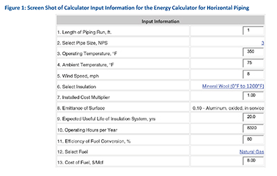 Figure 1
 Figure 2
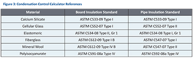 Figure 3
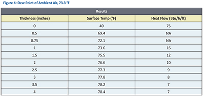 Figure 4