New Directions in Pipe Heat-Tracing Designs
Heat-tracing systems are often overlooked when industrial energy reduction initiatives are considered, but these systems are large energy consumers that may be optimized for energy conservation. A large variety of heat-tracing methods are available today.
Optimizing heat-tracing systems to be more energy conservative begins by selecting the most economic insulation type and thickness that meets the plant’s functional requirements, along with the best combination of heat-tracing method and control system for the application. A general overview of today’s energy-efficient heat-tracing systems is presented below, with a forward look at the anticipated impact of continually rising energy costs on heat-tracing technology. A case study is included to compare installation and operating costs of bare convection steam tracing and self-regulating electric tracing for water-freeze protection.
Debate on Steam Versus Electric Tracing
Ever since electric tracing emerged as a viable means of heat tracing in the early 1960s, there has been an ongoing debate concerning steam versus electric tracing and which method provides the most cost-effective and energy-efficient system for heating plant piping systems.
Electric heat-tracing quantities are estimated to be about 2/3 that of steam—and growing rapidly. Today, the installed base for electric heat tracing in the United States is estimated to be about 70 to 80 million feet.1, 2 It also is believed that electric tracing is easily controlled and therefore has the ability to maintain products within a narrow temperature range, reducing energy consumption.
Since electric tracing does not carry fluids, there are no fittings that leak or traps that will malfunction and require routine maintenance. In addition, modern, flexible electric heating cables can hold pipe temperatures at 40 F for simple freeze protection or process maintenance temperatures up to 400 F in applications that once were designed with steam or heat-transfer fluid tracing.
Finally, mineral-insulated heating cables with a tubular sheath of Alloy 825 (a high-nickel/ chromium alloy) are capable of holding pipe temperatures up to 932 F. Steam cannot be used safely at such extreme temperatures.
Still, many systems today consist of a bare convection steam tracer, which can be a sizeable energy consumer, as shown in the following case study. The apparent simplicity of a bare convection tracer belies the fact that the tracer is often installed on low-temperature applications where it then raises the pipe temperature much higher than needed. Even though overheating may not harm the fluid in the pipe, an enormous amount of energy is wasted.3
The total installed base of steam tracing in United States industrial process plants is estimated to be about 105 to 120 million feet, and bare convection tracing makes up about 80 percent (or 84 to 96 million feet) of the total.1, 2 Engineers involved in the design of steam-tracing systems indicate that at least 50 percent (or 42 to 48 million feet) of all bare convection tracing is installed for low-ambient freeze protection.4
All steam-tracing systems require traps to hold the steam in the circuit until it gives up its latent heat. The traps then release the condensate into a collection system. A typical chemical plant with 5,000 steam traps will have approximately 3,000 traps performing steam-tracing service.5 The plant will have approximately 180,000 feet of steam tracing with approximately 72,000 feet heated with bare convection steam tracing for winter-freeze protection. In most plants, ongoing steam-trap failures of 3 to 10 percent will contribute to the flow of live steam in the return line.6 If the plant has a good maintenance program, only about 3 to 5 percent of the traps will malfunction at any given time. Table 1 provides a look at the cost of malfunctioning small-orifice traps for steam-tracing circuits when steam cost is $10.00 per 1,000 pounds.
Another prevalent view is that temperature control methods are available for steam-tracing circuits, but they usually require shortened circuit lengths to maintain consistent temperature profiles. These control systems are sometimes costly to implement; therefore, it is more common to find steam-tracing systems operating in the “free run” mode.
Steam tracing has an advantage over electric in plants that produce steam from process heat since the steam will be considered free, or at least low-cost.
Steam tracing also may be used where flash steam is available from condensate released by a higher-pressure steam source since it will be low in cost. When steam is generated by a fired boiler, however, steam tracing rarely will be economically competitive with electric heat tracing.
Steam tracing is effective when heating process lines operate within 200 to 375 F, particularly if a rapid heat-up or melt-out is required in case of a process shutdown. Conduction steam-tracing systems (tubing tracers utilizing heat-transfer compounds) are often chosen for these applications.
Impact of Escalating Energy Costs on Future Heat-Tracing Design
There is no doubt that the installed base of heat tracing will continue to grow. Likewise, heat-tracing products and system designs will change in the years ahead, and the trends can be anticipated based on the level of technology today. As noted, there are many heat-tracing types available for heating plant-piping systems. It is expected that tubular steam tracing and self-regulating electric tracing will continue to be the predominant heat-tracing types in the future. Therefore, the remainder of this article will focus on these types.
Greater Sophistication in Heat-Tracing Controls
Simplicity in heat-tracing control equipment will become harder to justify in the future. The first rule of thumb in many heat-tracing design applications today is “simple is better.” This is especially applicable in the area of heat-tracing control strategies. The most common heat-tracing control strategies used today are as follows (beginning with the least-energy-conserving):
No Control—For self-regulating electric heating cable, the simplest control method is to take advantage of the self-regulating power turndown and free run capability of the cable and use no control at all. Unfortunately, today’s self-regulating heating cable technology does not lend itself to customized power curve shaping. The “turn down” of a self-regulating heating cable is determined by (1) the polymer base of the heater, (2) the conductivity of the formulation, and (3) the operating temperature of the heater. The actual pipe equilibrium temperature is then a function of the level to which the power turns down, along with the heat loss through the insulation envelope.
For steam heat tracing, the use of uncontrolled steam is quite common. Since steam is a constant temperature source, the heat delivered by the steam tracer will continue to reduce until the pipe maintains a static equilibrium temperature. With steam tracing, the tracer essentially turns off when the pipe approaches the steam temperature. In either case, a “no-control” strategy with heat tracing will result in raising pipe temperatures above the required values. The results of a typical no-control strategy for steam tracers and an electric self-regulating heating cable are compared in Figure 1.
From Figure 1, it is clear that even a polyolefin-based self-regulating heating cable with the highest turndown contributes to overheat (temperatures in excess of 40 F) and energy waste when operated in a no-control mode over normal ambient temperature swings of –20 to 100 F.
Ambient Sensing (On-Off) Control—One of the earliest and simplest forms of heat-tracing control is ambient sensing on-off control. With this control strategy, the power is switched to a single heater or group of heaters when a thermostat/controller senses that the ambient temperature has dropped below the preset temperature, which would normally be slightly above the freeze point of the fluid in the process or utility pipe. For freeze protection, the controllers are generally set at about 40 F. This type of control scheme has the following characteristics:
- No heating occurs when the ambient is above freezing.
- A single temperature controller can control a whole group of circuits when the circuits are in the same ambient temperature environment.
- This approach may be used with either steam or electric heat-tracing systems by turning off steam or electrical power at a central distribution location.
The disadvantage of this method is that overheating still may occur, since the power to all circuits is either fully on or off, and maximum watts/Btu/hr output is only needed at the coldest design ambient condition, which seldom occurs. Referencing Figure 1, the effect of ambient sensing control is simply to turn the heaters off when the ambient temperature climbs to 40 F.
Ambient Sensing (Wide Band Proportional) Control: Theoretically, if the ambient environment did not change throughout the year, it would be possible to apply one level of heat and maintain the same temperature throughout the year. Since that is not the case (except, perhaps, indoors in a controlled environment), the next best thing is to monitor the ambient changes with a special electronic temperature-control device that linearly proportions the power from a near-zero level at the desired maintenance temperature to full power at the minimum design ambient. This type of control system has the following characteristics:
- Only minimal overheating occurs as the power input cuts back when the ambient temperature begins to climb.
- A large number of circuits may be grouped together without regard for branches and flow patterns.
- Installed capital costs are only slightly higher than with the more traditional on-off ambient control.
- Due to the rapid on-off cycles of the control device, this methodology is best applied with solid-state control switching and thus should not be used with steam tracing.
The primary disadvantage of this method is that power to the heat tracing still will be on when flow is occurring at temperatures in excess of the desired maintenance temperature. That is, normally there is no feedback on the process piping temperatures when in operation. A typical control pattern that might be observed in this type of control scheme is shown in Figure 3.
In the range of –20 to 42 F, the pipe temperature is controlled by the proportional control algorithm, which usually has a lower power limit of 20 percent just prior to shutoff. Upon reaching 42 F (the upper end of the control band), the heat tracing is de-energized and the pipe will warm as the ambient temperature rises. This control strategy is not only applicable to water-freeze protection but also may be effectively used in process temperature maintenance applications.
Pipe Sensing Control—The most energy-conservative control strategy is pipe-sensing control, in which a temperature sensor is located on the traced pipe. The control device will turn the heat tracing on and off within a prescribed control band around the required maintenance temperature. The pipe-sensing control strategy has the following characteristics:
- Only the precise amount of heat required to hold the pipe at design temperature is applied.
- If fluid is flowing at a temperature above the control point, the heat tracing will turn off. In some cases, this may be necessary to prevent damage to the heat tracing being utilized.
- This method can be used for steam or electric tracing, although steam control systems available today are costly and are generally restricted to applications with rather short circuit lengths.
The primary disadvantage of a pipe-sensing control strategy is that most of the pipe branches need to be controlled by a separate control device, which increases the initial capital investment. Typical control patterns that might be observed in this type of system are provided in Figure 3.
In the range of –20 F to 42 F, pipe temperature is controlled by an on-off pipe-sensing control algorithm. Upon reaching 42 F (the upper end of the control band), the heat tracing is de-energized and the pipe will warm as the ambient temperature rises. This control strategy is applicable to all temperature maintenance applications.
In the future, the use of control strategies where natural overheating of the traced-piping system occurs will most likely decline in favor of more energy-conservative options of ambient proportional and pipe-sensing control.
The Insulation Envelope Will Grow in Thickness
As the cost of energy climbs, the economic insulation thickness by NAIMA (as determined by programs such as 3E Plus®) will naturally increase for most heat-tracing applications. The impact of increased insulation thickness on electric heating cables or steam tracers is that the watts/Btu/hr required to offset heat loss will drop. Within a particular family or class of electric heating cables, the optimal design will drift to the lower-wattage models, as illustrated in Figure 4.
The benefits to be realized from the expected trend toward lower-power electric-tracing products are as follows:
- Power distribution equipment size and cost will be reduced.
- Heater operating temperatures and system stress will be reduced.
- Depending on the magnitude of the insulation increase, it may be possible to move into a lower-temperature class of heaters and achieve initial capital cost savings.
The same general effect will be seen with steam-tracing products. Within a particular family of steam-tracing products, the optimal design will drift to the lower-heat transfer products, as seen in Figure 5.
An additional benefit with steam tracing is the possibility of using lower-pressure steam, which may be available from various let-down process operations.
On the other hand, for either heat-tracing product type, the use of thicker insulation envelopes does create the need to pay greater attention to pipe support and equipment allowance details. That is, it is typical in a heat-tracing system to place additional heater allowances at pipe supports and equipment where the insulation envelope must be breached by thermally conductive supports or appendages. In these cases, the traditional support and equipment allowances either must be increased as the heat output per unit length drops, or isolated pipe support systems should be considered.
As the insulation thickness on piping increases, it also becomes increasingly more difficult to properly size a steam-tracing product into lower temperature freeze-protection applications. The commercially available electric heating cables are already much lower in overall heat output compared to the steam-tracing products currently available. Unless new technology becomes available for steam-tracing products, the obvious trend will be that a greater percentage of electric tracing will be used in the future; the “Steam Versus Electric Tracing Question” will be answered.
How Rising Energy Costs May Alter the Future Heat-Tracing System Design Process
In many designs today, the energy costs associated with heat tracing are taken for granted. System design criteria are based on past historical success and familiarity with a particular type of heat tracing, initial capital cost of system and installation, and functional process specifications. Yearly operating costs based on energy consumption and maintenance activities are not often included in the design evaluation except in a very broad way. It is anticipated that this will soon change. Manufacturers and engineering providers will need to incorporate engineering and energy assessments within the overall heat-tracing system evaluation. The heat-tracing system design process flow diagram is shown in Figure 6.
Because of rising fuel costs, increased emphasis is expected to be placed on energy consumption and maintenance in the operational analysis phase of a project. Key factors to be considered in this part of the analysis are:
- Cost and availability of steam and electric utilities, with a projection of increases in fuel costs over the life of the system.
- Overheat capabilities of the heat-tracing system due to the control strategy.
- Historical ambient temperature cycle patterns and average wind on a monthly basis for the specific facility/region.
- Energy consumption of the heat-tracing system during product processing periods, as well as stagnant piping periods.
- Energy losses associated with normal operation and wear and tear of heat-tracing equipment such as steam traps.
Technology and the tools for evaluating electric and steam heat-tracing systems with more precision are already in the latter stages of development.
To illustrate the results of an overall heat-tracing design-and-build project with the added energy assessment, consider the following.
A Case Study Illustration
A 2 1/2-inch pipe utility water system totaling approximately 1,000 feet of piping is to be freeze protected at a minimum temperature of 40 F with a low ambient design temperature of –20 F. Both steam- and electric-tracing systems will be evaluated. A polyolefin-based self-regulating electric heating cable operating at 240 Vac with ambient sensing control will be compared with a 3/8-inch conventional steam-tracing tube having a 30 psig steam supply source. The steam tracer operates in a free run mode. The most functional insulation type and economic thickness, based on projected energy cost over a 20-year period for this application, previously has been determined to be 1-inch cellular glass. Evaluate the initial capital investment cost of the heat tracing, thermal insulation and distribution system and determine the yearly operating cost (which includes an energy consumption assessment).
The evaluation shows that the initial installation cost of the steam-tracing system was about 17 percent higher than the ambient sensed self-regulating cable system. This was primarily due to the higher cost of installing the steam distribution system compared to the electric distribution system. The energy and operating costs of the steam-tracing system was in excess of $5,000 per year more than the electric-tracing system in this case study. The energy cost differential in favor of the electric-tracing system was due to the use of an ambient sensing control strategy as well as the much greater energy consumption of the steam-tracing system and associated steam traps.
Projecting Plant Cost Savings
It is possible to take the above case study results and extrapolate them to numbers on a plant-wide basis. For example, the typical petrochemical plant from Table 1 (5,000 traps, 3,000 of which are on steam-tracing service) would have approximately 72,000 feet of pipe requiring freeze protection. Based on a general statistical analysis of pipe size demographics within a petrochemical facility, the 1,000-foot long, 2 1/2-inch pipe selected for the case study is a good average size since over 2/3 of the small piping is in the 2- to 3-inch range. It is reasonable to project that a typical petrochemical plant could potentially save approximately $360,000 (72,000¸ 1,000 x $5,000) in energy cost per year if the lines were traced with self-regulating electric tracing rather than bare convection steam tracing. This does not consider the initial capital cost savings that will result from using the electric-tracing rather than the steam-tracing system.
The Future
The engineering design-and-build world is now and will most assuredly continue to be affected by the need to reduce hydrocarbon pollutants and energy consumption. Increased engineering design awareness and analysis of energy consumption and emissions is rapidly becoming a fact of life. Movements in the technology area to utilize nanotechnology in the development of unique, new, enhanced materials are beginning to be more than just a research idea in the insulation and heat-tracing arena. Steady advances in electronics, such as wireless technology, will no doubt bring about the commercialization of new control and monitoring equipment, which will result in more effective, energy-efficient heat-traced piping systems. The future is certainly bright, with new engineering challenges and opportunities for the heat-tracing and insulation industry.
Endnote References
1. Custom Marketing Report for Thermon Manufacturing Company, Saunders Management Associates, September 1994.
2. Thermon Heat Tracing Services, Inc., A Turnkey Heat Tracing Contractor.
3. Burdick, Dick. “Steam Versus Electrical Tracing,” Insulation Outlook (Viewpoint), May 1999.
4. McDonald, Arthur. Special Report, Thermon Manufacturing Company, March 2000.
5. Jones, Ted. “Gathering Steam,” Insulation Outlook, March, 1998.
6. Mackay, Bruce, P.E. “Designing a Cost effective Condensate-Return System.” Chemical Processing, May 1997.
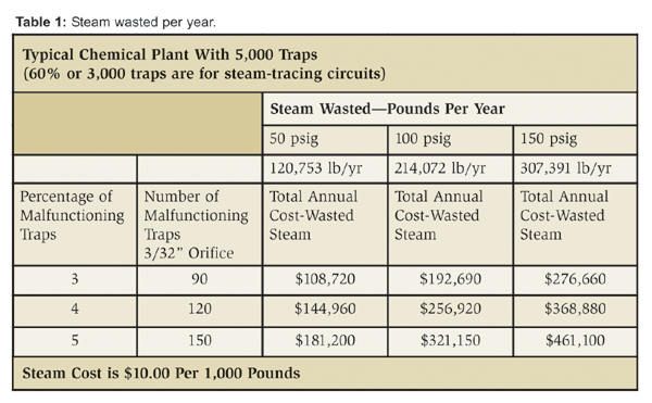 Figure 1
Table 1: Steam Wasted per year.
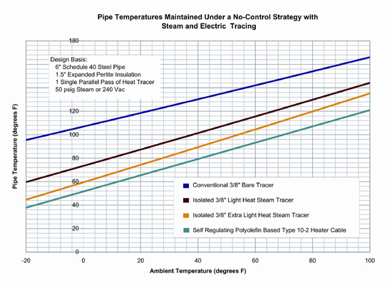 Figure 2
Figure1: typical temperature levels achieved with self-regulating polyolefin heating cable, bare steam tracers and isolated steam tracers for water-freeze protection when a no-control strategy is implemented.
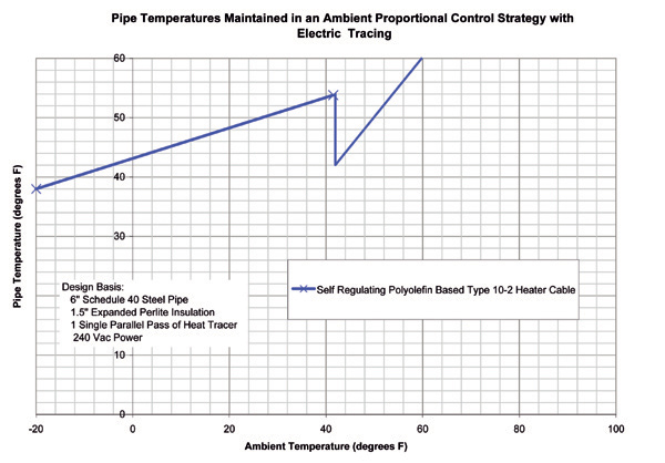 Figure 3
Figure 2: Typical temperature control achieved on a pipe with self-regulating polyolefin-based heating cable when an ambient proportional control strategy is used.
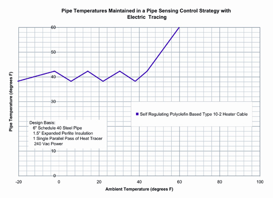 Figure 4
Figure 3: Typical temperature control achieved with a self-regulating polyolefin-based heating cable where a pipe sensing control strategy is used.
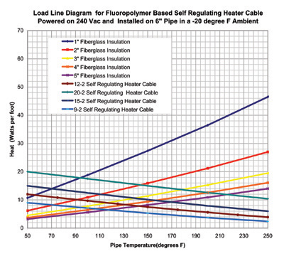 Figure 5
Figure 4: Typical load line diagram for a pipe heat traced with a fluoropolymer class of self-regulating heaters as insulation thickness increases.
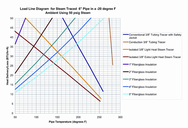 Figure 6
Figure 5: Typical load line diagram for a pipe heated with steam tracing as insulation thickness increases.
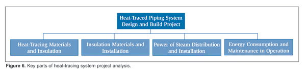 Figure 7
Figure 6: Key parts of heat-tracing system project analysis.
 Figure 8
Figure 7: Developing engineering tools for heat tracing and energy assessments.
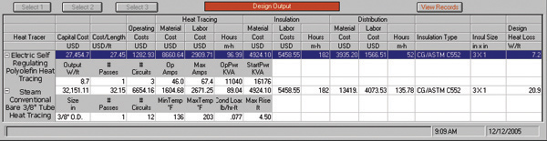 Figure 9
Figure 8: Computer analysis results of installed and operating tracing system costs.