Pre-Insulated Lagging Panels
In the United States, energy conservation, power capacity and greenhouse gas emission reduction are serious issues. They have affected almost every industry in the country, including those involved in power generating. New boiler construction was almost non-existent for 10 years. Now, seemingly overnight, everyone needs to build a new steam-generating boiler. Designing, manufacturing and constructing a 600-megawatt boiler used to take three years. Now it can be done in less than two. Government mandates on NOx emissions have also put a lot of pressure on scheduling, from design to construction. When schedule is the driving issue, it affects every component, including insulation and lagging.
In the "old" days it was a common construction practice for the insulation and lagging to start after all the equipment was erected. (See Figure 1.)
Today it’s rarely done that way. To meet schedule requirements, flues, ducts and equipment are being insulated on the ground with pre-insulated lagging panel systems (sometimes referred to as packed panels). (See Figure 19.)
Panel Issues
It may help some readers to review a few items.
Pre Insulated Lagging Panel System
A pre-insulated lagging panel system is a lagging and insulation system that consists of a shop-or-field fabricated aluminum-lagging sheet lined on the backside with insulation. The aluminum lagging is laid face down on a table in the shop. The insulation pins are welded to the lagging sheet on approximately 12-inch centers. The insulation material is impaled over the pins. Aluminum foil is placed over the insulation. The foil will reflect some of the heat back in and is equivalent to about a 1/2 inch of insulation. A galvanized mesh (generally 2 inches x 2 5/8 inches, 16 gauge) is placed over the foil.* The mesh keeps the insulation in place, which will prevent the fibers from settling to the bottom. A 2-1/2 inch square speed clip is placed on the pins, which are bent over to hold the panel together. This insulated lagging sheet or panel will then attach to the outside of the stiffeners directly or to a sub system made from angle iron.
(*The aluminum foil and the mesh will help retain the integrity of mineral wool board insulations. The foil could be eliminated if using fiberglass insulation and the application is for low temperatures of 350 degrees Fahrenheit [F] and below.) (See Figure 2.)
There are several important panel issues to know.
-
A pre-insulated lagging panel utilizing a 4-inch thick mineral wool, 8-pound density insulation and .032-inch box rib aluminum lagging weighs approximately 4-1/2 pounds per square foot. This weight is important to know when calculating crane sizing for lifting the ground-insulated pieces to elevations. Ten-foot long panels can be very difficult to handle because they will weigh as much as 200 pounds.
- Clearances also have to be observed due to the entire insulation and lagging system being installed outside the stiffeners.
- Material storage space must be readily available, because a pre-insulated lagging panel system is a pre-designed system and the panels must be made in quantity and ahead of time. All of the stored panels must be weather protected, because water damage is the leading insulation killer. (See Figures 3 and 4.)
Panel vs. Conventional
Since the early to mid 1970s, boilers and their associated hot flues and ducts (above 350 degrees F) were almost always insulated and lagged using a conventional insulation and lagging system*. Some original equipment manufactures of boilers for instance, never used a pre-insulated panel system on their boiler and furnace walls, but did use panels on some hot flues, ducts, air-heaters, economizer casings, and penthouse vertical walls from 1968 to 1975.
(*A conventionally insulated and lagged system is a system where each component will be attached separately. In most cases, due to the size of the stiffeners being designed today a sub-system (inner insulation support or H-bar type system) may also be required. One such conventional system (and there are many systems out there) is the insulation pin and sub-girt system**.)
(** The insulation pin and sub-girt system utilizes 10-gage insulation pins and a perforated 3-inch wide sub-girt or hat channel to attach the lagging. Insulation pins are laid out (6-inch horizontal spacing) so the lagging will have sufficient support based on the wind-loading span. After the insulation has been installed (impaled) over the insulation pins a sub-girt channel or hat section will be installed to these pins by using an insulation speed clip. The lagging will then be screwed into the sub-girt.) (See Figure 5.)
The Changing of the Guard
It’s this conventional system, as described previously, that’s now being replaced by the pre-insulated lagging panel system for almost all hot flue, duct and selective catalytic reduction systems. This is due in part to the very tight erection scheduling, requiring ground assembly and the very large stiffeners being designed on the equipment. Up to now, panels have been used on some hot flue systems operating as much as 750 degrees F, but they haven’t been utilized on boiler and furnace walls. Cold flue and duct systems operating at 350 degrees F and below have utilized pre-insulated lagging panels for more than 30 years. (See Figure 6.)
When utilizing a panel system on hot flues and ducts and equipment, including a selective catalytic reduction system, you should take note of the following information:
- Ensure that adequate supervision and attention is paid to the design of the pre-insulated panel system and the installation.
- Ensure that adequate clearances are kept between all obstructions.
- When ground assembling of equipment, ensure that enough un-insulated area is left exposed to allow the welding or attaching of the insulated flue or duct pieces. (See Figures 7 and 8.)
- Ensure that you have accounted for the weight of the panel system to the flue or duct piece that’s being lifted.
- Don’t use pop rivets or a Hilti type fastener system if there’s a lot of vibration expected during operation.
- Ensure that the panel system can resist 30 psf positive and negative wind force without loss of weather barrier integrity.
- Ensure that panels are properly flashed and sealed around penetrations such as support brackets, poke holes, and man-ways by using mitered edges and segmental cuts to reduce caulking and buttering to a minimum (See Figure 9.).
- Ensure that every penetration through a vertical surface has a "drip-lip" type flashing and is caulked (See Figure 10.).
- Ensure that all vertical surfaces, including hoppers, with vertical runs greater than 10 feet long have a thermal barrier installed to prevent stack effect of hot air. (See Figure 11.)
- Ensure that closure strips are used at all open ends of lagging that aren’t otherwise flashed. Closure strips must be recessed back from the extreme edge of the sheet and must be properly held or supported to prevent slippage.
Expansion and Contraction and Caulking
All lagging panels must be applied over areas to present a true plane. Then it’s stiffened and fastened on adequate centers to prevent excessive deflection or "oil canning" when hot or cold. (See Figure 12.)
Expansion and contraction requirements represent a major problem for lagging panels. Necessary provisions for expansion and contraction must be provided to maintain a neat and proper design when in service. It’s critical to note that when a panel system is being utilized today, a large portion of the work is being done on the ground. The expansion areas and tie in areas will be finished at elevation after the flue or duct pieces have been lifted and installed. Here are some useful tips to follow:
- Sealing by welding, soldering, or caulking is permissible consistent with temperature limitations and expected expansion and contraction.
- Attachments for the panels shall be spaced in set patterns both vertically and horizontally to present a uniform appearance. They shall be located on centers to prevent rattling or "oil canning" due to expansion or vibration and maintain the specified wind loading.
- Lagging panels when used over expansion joints shall be designed to provide movement equal to the expansion of the joint covered.
Panels on Boiler and Furnace Walls
Since the mid to late 1970s, pre-insulated lagging panels have been used predominately only on flues and ducts operating at 350 degrees F or below. Prior to that, panels were being used on some hot flues, ducts, and equipment but, not on boiler and furnace walls. Scheduling was not an issue at the time. The insulation work was done during the final phases of construction at elevation, and therefore the panel design and installation became impractical. The combination of long erection schedules, and the material handling and labor production problems eventually led to panels being, for the most part, eliminated from the construction options for installing insulation and lagging on flues, ducts and equipment operating above 350 degrees F.
Today, due to the tight erection schedules and ground assembly, panel systems are again being considered on all surfaces including boiler and furnace walls. There are many applications where this might be a viable option. These include:
Shop installation
In shop installation, the boiler tube panels with buckstays attached would be laid out on a shop floor, and the entire system of tube panels (with the insulated lagging panels attached) are shipped directly to the job site.
Hot installation
In hot installation, when the boiler is in operation, panels could be used in lieu of a conventional application. Hot installation (installing insulation and or lagging when the boiler is running) requires specific expansion designs. In my opinion, I think pre-insulated panels would be a viable alternative to a conventional system. The expansion would be designed into the panel construction.
However, there will always be concern in the industry about material handling of panels (size and weight of a panel), wall penetrations, protrusions and doors. However, I don’t believe that the problem about penetrations, doors, and protrusions is limited to just pre-insulated panels. Penetrations, doors, and protrusions exist on only about a third of all boiler and furnace wall surfaces, and they must be addressed even when installing a conventional insulation and lagging system. To me, the approach would be the same for installing panels as it is for a conventional insulation and lagging system when dealing with any type of penetration, door, or wall box. The ease or difficulty as to how that would be done with panels versus a conventional insulation and lagging system isn’t the point of this article. As for the size and weight problem of panels, that’s an issue of concern whenever you’re installing a panel system, and I see it as no more difficult to do or overcome than when installing panels on SCR flue-work.
To install a panel on a boiler or furnace wall will require a special attachment such as the one shown on the following drawing. These attachments will be required at the top and bottom areas where the panel will be attached. Wherever support spacing dictates, additional support rows should be added. The advantage of using a panel design is that the supports can be installed in the tube panel shop prior to shipping to the field for erection.
The pre-insulated lagging panels must be designed and installed to fit between buckstays and flashed and or attached at the buckstays as shown on the following drawings: (See Figures 13, 14 and 15.)
Significant Pointers
The advantage of installing a pre-insulated panel system on flues, ducts, or boiler and furnace walls, in lieu of a conventional insulation and lagging system, is the potential for lower installation cost. The panels can be fabricated at an outside fabrication shop more cheaply than using field labor. Then the panels can be installed in one operation. The problem with panels is that everything (design, fabrication, and installation) must be done correctly for the system to work. When something goes wrong with a panel system, the problems are magnified when compared to problems on any conventional system.
A panel system will expand more than a conventional system because the entire system (insulation and lagging) must expand together. The expansion must be incorporated into the panel sub system and is critical for proper expansion. An example: in a system operating at 850 degrees F, each panel must be able to accommodate 1/2 inch of expansion in the direction the ribs are running. The horizontal laps must not be fastened together so that each row can move independently to the adjacent rows. Each joint must be fitted tightly so that when the unit goes into operation, large voids aren’t opened. The horizontal expansion isn’t a specific problem because, like any conventional system, the "accordion effect" of the ribs take up the expansion.
Panel systems require extensive lay down and storage area because they must be manufactured ahead of time and stored at the site. Because panels are heavy, the storage area should be close to the work area, and all the panels must be marked and or tagged for the location that it was fabricated and designed. Therefore, although panels are cheaper to install, they require more handling and storage needs. (See Figure 16.)
Each panel is specifically designed and fabricated for a specific location, and must be installed in sequence (similar to laying brick). You must start at the bottom and work across each row before you can install the next row. This means that the erection sequence must be figured into the entire construction schedule. A conventional system is more schedule-friendly than a panel system. It happens many times when the construction schedule was changed and thus caused large amounts of surface area needing to be insulated (and lagged) in a very short period of time. Panel installation doesn’t lend itself to quick installation because panels are a pre-designed system and require extensive material handling.
The type of insulation used on a panel system is also critical. On a low temperature application of 500 degrees and below, fiberglass or mineral wool type products can be used (and have been for more than 30 years). The fiberglass is half the weight of the mineral wool products, and makes the panel easier to handle. However, it’s not recommended using fiberglass on applications above 500 degrees F due to the lower compressive strength and lighter density. At higher temperatures, the fiberglass allows heat to migrate up within the insulating material itself, and can cause the much lighter insulation to shrink more than the mineral wool products. This increases the potential for hot spots on the lagging surface caused by heat escaping through the cracks created by the shrinking fiberglass material.
Money Saving Tips
Shop fabrication of panels can save money because most shop labor costs are cheaper than field labor. However, it’s not recommend because shop-installed panels can get easily damaged during shipping. It’s recommended to have the sub-girt system for the support of the panels to be shop installed. This will create an estimated savings of approximately 0.75 per square foot in field labor cost. Ground assembly is another money saver, but only if the piece to be covered is off the ground for ease of panel installation. Estimated labor savings could be $1 to $2 per square foot compared to installing the panels at elevation. (See Figures 17 and 18.)
Conclusion
Pre-insulated lagging panels can be an excellent insulation and lagging system for use by the power generating industry, as long as attention is given to detail and design. Pre-insulated lagging panel systems are a pre-engineered system that requires very clear and defined drawings for installation. The panels must then be manufactured with close attention to the tight tolerances, the erection schedule requirements, the installation, the supervision and the material handling and storage. An assortment of things can go wrong with a panel system. However, if properly designed, manufactured, installed, and supervised, panels can help industry meet their scheduling requirements and get their steam-generating boilers back on line and on schedule.
Gary Bases is president of BRIL, inc., an independent consulting firm specializing in brick, refractory, insulation, and lagging where energy saving solutions are possible. Contact him at (330) 665-2931 or brilinc@raex.com.
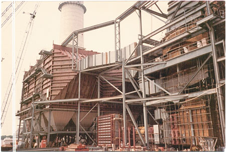 Figure 1
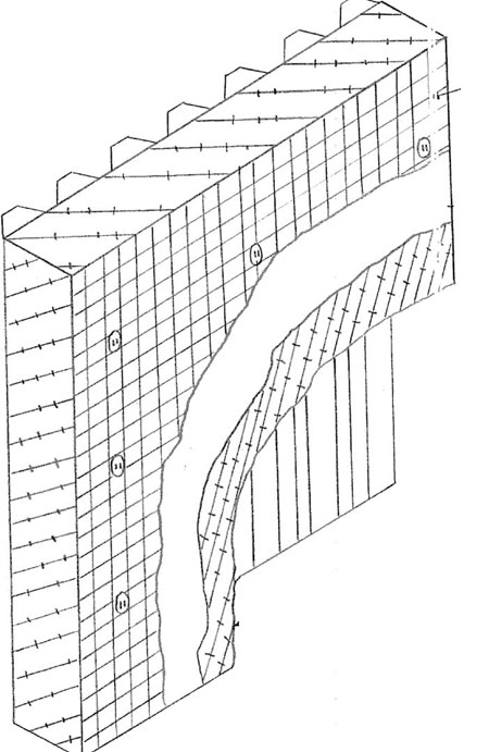 Figure 2
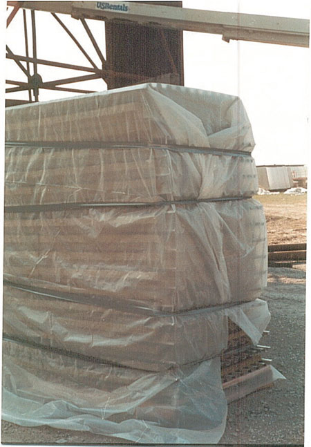 Figure 3
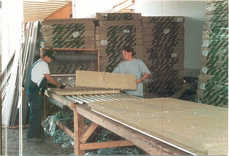 Figure 4
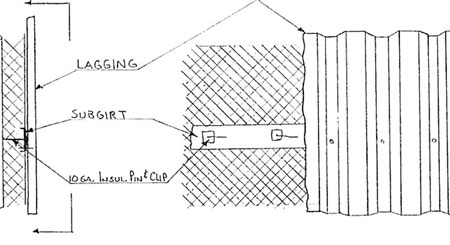 Figure 5
 Figure 6
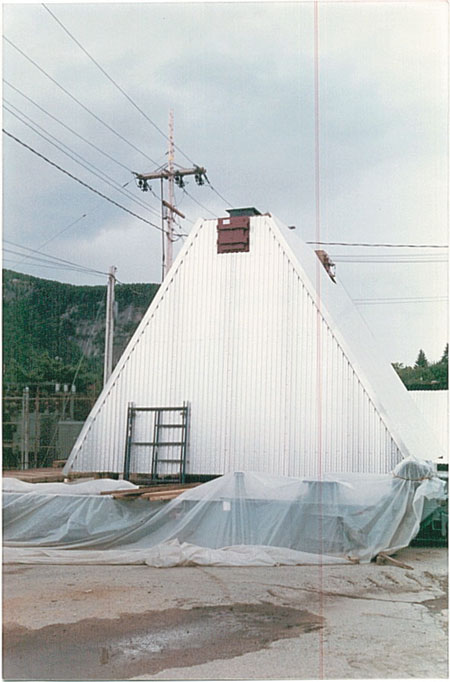 Figure 7
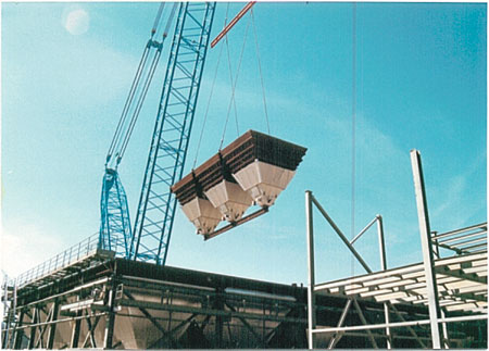 Figure 8
 Figure 9
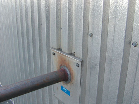 Figure 10
 Figure 11
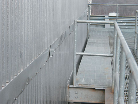 Figure 12
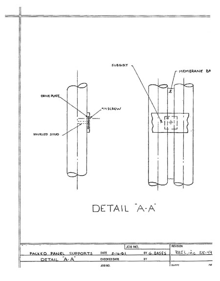 Figure 13
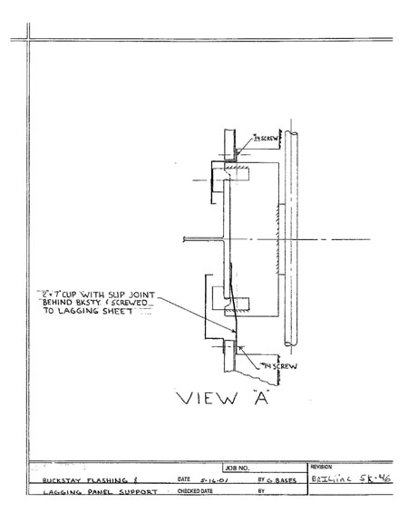 Figure 14
 Figure 15
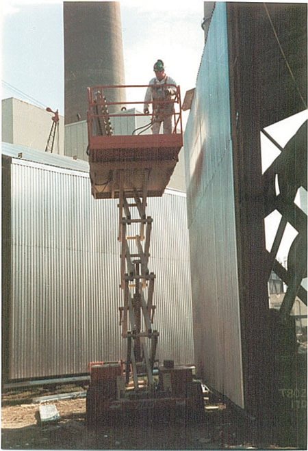 Figure 16
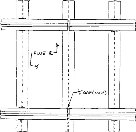 Figure 17
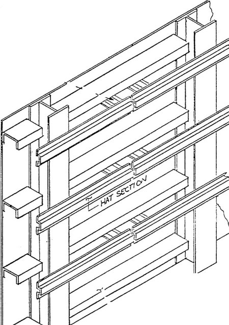 Figure 18
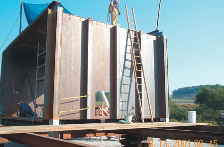 Figure 19