Ship Configurations: Insulation Design and Application
The steel boundaries of ocean-going ships are thermally insulated for basically the same reasons we insulate the envelopes of buildings: to reduce energy use for space heating and cooling; to provide an acceptable thermal environment for occupants; to prevent moisture condensation on the walls, roofs and ceiling; to protect against the spread of fire; and to protect stored goods and materials. In some instances, bulkhead insulation is required to mitigate noise migration for occupants. The piping and mechanical equipment on ships are insulated for the same reasons we insulate the piping and equipment at industrial facilities or commercial buildings: to reduce process or HVAC-related energy use; to reduce loads on mechanical equipment; to provide personnel protection; and to reduce noise. Increasingly, we insulate to reduce quantities of emissions and thereby reduce the adverse impact on the environment.
For more than 40 years the American ship construction industry has relied on a document first published by the Society of Naval Architects and Marine Engineers (SNAME) in 1963 for the selection of hull insulation thicknesses. While thermal insulation standards in residential and commercial buildings and in industrial environments have changed dramatically in those 40 years–due to significantly higher energy prices and to a greater understanding of insulation performance–those standards for the American marine industry have not changed.
There are a number of reasons for insulating the shells, bulkheads and decks of ships.
Variant Spaces
Crew members may occupy or work in a variety of areas aboard ship. Whether living spaces, cargo spaces or workspaces, the various compartments within a ship need to meet certain acceptable criteria for either human comfort or for acceptable working conditions. To maintain inside air temperatures within an acceptable range, heating and cooling systems must be designed in combination with thermal insulation systems. In stowage spaces, cargos are often protected by maintaining air temperatures and moisture levels within predetermined limits. In machinery and equipment spaces, temperatures and moisture levels must likewise be kept within acceptable limits. Frequently within a ship, one cargo space or mechanical equipment space may need to be kept at a different temperature than an adjacent space, requiring structural insulation to thermally separate the compartments.
Surfaces Above and Below Water Level
The shell boundaries and decks of ships are, in some ways, thermally like the exterior walls and roof of a building: They separate an interior temperature- and humidity-conditioned space from outdoor conditions. In the case of ships, however, there are no walls above ground and below ground. Rather, there are the parts of the hull above water, exposed to ambient air, and the parts below water, exposed to the ocean water. For the portions of the hull that are below water level, because the water temperature can be much lower than the inside air temperature and because the heat transfer coefficient from water is much greater than for air, insulation must both limit heat loss to the water and prevent moisture condensation on the cold steel surfaces. However, the heat transfer through a ship’s shell is most extreme where the stiffeners act as heat transfer "fins" which, if not insulated, significantly increase the overall heat transmission. The typical minimum design outdoor air temperature for heating conditions is 0 F; the typical maximum design exterior surface for cooling conditions is 135 to 155 F, values that account for a combination of both a hot air temperature and strong incident solar radiation.
Changing Climactic Conditions
For a building, which is of course stationary, the ambient conditions typically change over the course of a year, with the expected ambient conditions depending on both location and time of year. In the case of a ship, which travels, perhaps all over the globe to different climactic conditions, those ambient conditions will vary by both location of the ship and time of year. The ship’s envelope and heating and cooling systems should therefore be designed for the extremes of those ambient conditions.
Weight From Generators and Fuel
Diesel generator units are typically used to generate electricity on a ship, and this electricity is used to power both resistance space heaters as well as vapor-compression, air-cooling systems. These diesel generators, of course, require diesel fuel to operate, and this fuel must be carried within the ship, adding to the total weight of the ship. Also, the diesel generators must be sized adequately to provide sufficient electrical power for both the coldest conditions, perhaps in polar zones of the Earth, and the hottest conditions, perhaps near the equator. The larger the generators and the greater the amount of diesel fuel, the greater the overall weight of the ship. In the ship construction industry, weight limitation is a very important design consideration. There should be a strong, inverse relationship between the amount and location of installed thermal insulation and the total combined weight of the diesel generators and the diesel fuel to power them. Unlike stationary buildings on land, this is an extremely important issue for ships.
Structural Members
All building walls, ceilings and roofs have structural members. Typically, for the walls and ceilings that make up the building’s thermal envelope, thermal insulation must be placed between or over the studs and joists. For an industrial facility envelope wall, such as the side of a huge flue gas duct at a coal-fired electric generating station, those panels will be placed on the outside of the duct, over top of the structural members. In the case of a ship, the thermal insulation has to be located inside the steel hull or below decks. The hulls and decks, in turn, are structurally reinforced with stiffeners running vertically on the hulls and perpendicular to the axis of the ship on the decks. To provide an effective thermal envelope, with a low "U" value, the thermal insulation must be placed against the steel boundaries and around the steel stiffeners, facing the conditioned space. Figures 1 and 2 show uninsulated and insulated stiffeners. When conditions warrant, the industry attempts to design the insulation for the unstiffened side of an internal bulkhead since that surface is planar and hence easier to insulate.
Hull Insulation
The thermal insulation material used for exposed structural boundaries such as the shell, bulkheads and decks is referred to as "hull board" or "Navy board." The standard military specification for thermal insulation material for U.S. Navy vessels’ hulls is MIL-I-742. This is a semi-flexible, nominal 2.8-lbs/ft3 fibrous glass wool with 3 percent organic binder content. These boards are typically faced with a heavy-duty, very durable, coated, woven fiberglass cloth. Standard practice requires that this product be installed on the ship hulls using weld pins, washers or drive-on caps. A weld pin and its cap are shown alone in Figure 3. For structural reasons, based on ship vibration, these weld pins are typically installed with 12- to 18-inch spacing and no more than 6 inches from the edge of a board. A matching white, woven glass fiber tape is applied over the facing joint of two adjoining boards.
SNAME Technical and Research Bulletin 4-7
While there are many types of thermal insulation on a typical ship, let us focus on the insulation criteria and methodology for the selection and installation of semi-rigid insulation boards on structural boundaries, such as the ship’s hull or shell, bulkheads and decks.
The standard for determining hull insulation thicknesses, for both U.S. built commercial vessels and Navy ships built to commercial standards, is given in SNAME Technical & Research Bulletin 4-7, Thermal Insulation Report. This is indeed a research report that is thorough and well-documented. It was founded on a series of thermal tests that were conducted to determine insulation performance in combination with two-dimensional angle stiffeners. In the resultant data, the thermal requirements for hulls, bulkheads and decks are given in terms of maximum allowable thermal transmittance values, or U-values. Insulation thicknesses are then derived from those values. These maximum allowable U-values are given in a SNAME document shown in Table 1.
To use Table 1 to determine hull insulation thickness, you must first know the design temperature difference for the particular section of insulation. Using other tables in the research report, you then can determine the surface coefficient values for the particular air temperature difference, direction of airflow and location of the air film. You then determine the thickness using still another set of tables, based on those thermal tests conducted in the early 1960s, which account for additional heat loss due to the presence of the rib stiffeners. These insulation thickness tables go on for many pages, with different sets for insulation thickness and choices for direction of heat flow, winter or summer conditions, and boundary conditions (inside air to outside air, inside air to sea water, inside air to inside air).
The tables are based on 36-inch stiffener spacings for angle stiffeners measuring 6 inches by 4 inches. Since there are numerous other stiffener spacings, angle stiffener sizes and stiffener designs used in ship construction, using these tables for insulation thickness determination can be difficult. In the SNAME document there are, in fact, other tables for stiffener spacings other than 36 inches, and these can be used to adjust the U-values obtained from the insulation thickness tables. However, because they are premised on a single size of a single angle type of stiffener, they cannot account accurately for the U-values for the wide variety of stiffener design variables found in the decks, bulkhead assemblies and other thermal boundaries encountered even within one ship.
For example, to illustrate a design problem, let us say that we are considering a portion of the hull that separates heated inside air at 60 F from cold outside air at 0 F during the winter conditions, giving a design temperature difference of 60 F. In this instance, there is no lining separating the hull from the indoor air. So, Table 1 shows our maximum U-value allowed, for a temperature difference for over 50 F, of 0.16. From experience, we know that the ends of the angle stiffeners will need to be covered with insulation; it will not be enough to simply insulate the plane surfaces of the hull. Flip through the pages of tables looking for the configuration just described, and there is one that meets the maximum U-value allowable of 0.16. For horizontal heat flow, winter conditions, for "Inside Air to Weather Air," with 2 inches of insulation board on the hull and 1 inch completely over the angle stiffeners, the table gives a U-value of 0.131.
Now, the contractor may consider that he could save some material and labor by not insulating the angle stiffeners to that degree. However, if he were to leave the stiffeners uninsulated, this would obviously result in a higher U-value for the hull. To determine that U-value, one would look at Type 50, which has the same 2 inches of insulation board on the hull but none on the angle stiffener. There, he can see that his U-value would be 0.326, a value that greatly exceeds 0.16. Therefore, for this set of design conditions, the contractor will have to insulate the angle stiffeners as well as the flat surfaces between the stiffeners to reduce the U-value below 0.16.
For those who are accustomed to using computer programs such as 3E Plus®, this SNAME methodology is reminiscent of how things used to be done in the design-engineering world. It needs to be reminded, however, that this SNAME document, while dated, is incredibly comprehensive and detailed for the subject matter it is addressing, namely two-dimensional heat transfer through a combination of steel and fibrous glass board insulation, with two fluid boundary conditions. The most practical way to really improve on this methodology with modern technology is with Finite Element Analysis (FEA), a heat transfer methodology for which there are very few practitioners in the insulation industry. Further, while it is commendable that this SNAME methodology takes account for two-dimensional system thermal performance, it does not allow for variations in system design that might provide an equal thermal performance with either less insulation or with a less labor-intensive application. Therefore, FEA may be the only way we can improve on this SNAME methodology. Please note that 3E Plus® will not do the job accurately since it assumes one-dimensional heat transfer and therefore cannot account for heat transfer through the two-dimensional angle stiffeners.
Comparing SNAME to ASHRAE Standards
Returning to the SNAME document in Table 1, the question arises whether these maximum allowable U-values are adequate for today’s energy costs and practices. A good basis for comparison would be the ASHRAE Standard 90.1-89, Energy Efficient Design of New Buildings Except Low-Rise Residential Buildings. This standard has been adopted by many states as a commercial building energy code. It gives listings of various cities, by state, around the United States with corresponding maximum allowable U-values for opaque walls and for roofs and ceilings. For example, in the fairly cold climate city of Indianapolis, Ind., the U-values are 0.092 and 0.058, respectively. Comparing each of these two values to the SNAME U-value of 0.16, (the case in that document requiring the most insulation, for an indoor-outdoor temperature difference greater than 50 F), one can see that the ASHRAE requirements are significantly more severe than the SNAME requirements. That is, for the same conditions, an ASHRAE opaque wall U-value of 0.092 would lose 43 percent less heat than the SNAME U-value of 0.16, and an ASHRAE roof/ceiling U-value of 0.058 would lose 64 percent less heat than the SNAME U-value of 0.16. So, based on these comparisons, it is clear that the SNAME U-value requirements have not kept pace with today’s insulation practices as typified by ASHRAE Standard 90.1 for metal buildings.
Other considerations are the assumptions behind the SNAME design methodology. The issues that skew the thermal performance of stiffened, insulated boundaries are the spacing and the configuration of the stiffeners. The data in SNAME Technical Bulletin 4-7 is based on using angle stiffeners measuring 6 inches by 4 inches. Tests conducted more than four decades ago and using 4-inch by 3-inch by ¼-inch angle stiffeners were used to validate the tables. These angle stiffeners no longer predominate. Stronger steel is now used in ship construction and the stiffener design has changed: Ships are increasingly constructed with bulb stiffeners. Figure 4 shows, side by side, both a 4-inch by 3-inch by ¼-inch angle stiffener and a 9.45-inch by 0.39-inch bulb stiffener. While the same basic heat transfer and insulation issues confront us, the design is different, and so the assumptions, upon which the SNAME design methodology is based, are no longer valid. Because of this, there is a choice: Either conduct a whole new set of heat loss tests, such as were done more than 40 years ago using the new bulb stiffener design, or have an engineer skilled in the use of a FEA heat transfer computer program model these new stiffener configurations and perform analyses to find solutions for particular design problems. We recommend the latter.
Need for Insulation Improvements
While a cursory comparison to DOE recommendations for home building insulation thicknesses makes the SNAME requirements look inadequate, an ocean-going vessel is not a house. We need to look in more depth at energy use on a ship to determine what hull insulation actually does.
The space air heating energy on a ship is provided by electrical resistance heat. Diesel generators generate the electricity with an operating efficiency of about 40 percent (e.g., the ratio of electrical energy generated to the energy content of the diesel fuel burned). To generate a kilowatt-hour of electrical energy then, one can compute the amount of diesel fuel that must be burned. Assuming a diesel fuel content of 19,000 Btu per pound, calculations show that about 1.2 pounds of diesel fuel, or about a fifth of a gallon, is needed to generate each kilowatt-hour of electricity. For electric resistance space heating, we can safely assume 100 percent conversion of electrical energy to heat.
For the purposes of an example, let us assume that we have insulated the above water portion of the hull with the solution from SNAME Table 17 found above: 2 inches of hull board insulation over the hull and 1 inch of hull board insulation over the angle stiffeners, an insulation configuration that we saw provides a U-value of 0.131. Let us further assume that a ship travels for a month between refueling stops and that it experiences heating season conditions with an average indoor to outdoor temperature difference of 40 F. Under these circumstances, calculations show during that month, each 1,000 square feet of hull surface area would require about 180 gallons of diesel fuel. Assuming a price of $1 per gallon for diesel fuel, the monthly fuel cost would be about $180 per 1,000 square feet of hull for space heating. Is this expensive? That would depend on the ship itself and on the duration of its operation between refueling stops.
Now, to determine whether it might be worthwhile to better insulate the hull, let us propose using 4 inches of hull board insulation, instead of 2 inches, but still with 1 inch on the angle stiffeners. According to Table 19 of the SNAME document, that insulation system would provide a U-value of 0.065, about half the 0.131 U-value with a 2-inch hull board thickness and "inside air to weather air" horizontal heat flow. Calculations then show that this additional 2-inch insulation thickness would of course add weight, about 470 pounds of weight per 1,000 square feet of surface area, but would reduce the diesel fuel use by half, on a square-foot basis. That is, the monthly use of 1,370 pounds of diesel fuel consumed per 1,000 square feet could be cut in half to 680 pounds of diesel fuel per 1,000 square feet just by doubling the thickness of the insulation board, only adding 470 pounds per 1,000 square feet of thermal insulation! This represents a monthly "weight payback savings" of 220 pounds per 1,000 square feet of surface area. Further, the monthly cost of the diesel fuel saved would be about $85 per 1,000 square feet simply considering the value of the reduced use of diesel fuel. So, in summary, the 2 inches of added insulation board would significantly reduce the weight and reduce operating cost of the ship in just one month.
It is important to note that the reduction in heating and cooling loads, resulting from the use of thicker hull board insulation, could also reduce equipment weight and equipment cost. That is, the size of the diesel generators and the size of the cooling units could consequently be reduced. That, in turn, would reduce weight and reduce first cost of constructing the ship, in spite of the thicker hull board insulation.
It is beyond the scope of this article to perform detailed calculations for weight reductions achievable by using smaller diesel generators. However, as an example, a 21,600-kilowatt, marine-style diesel generator from a particular manufacturer is listed on its website as having a weight of 264 metric tons. If that same manufacturer’s 14,400-kilowatt diesel generator, which is listed as having a weight of 190 metric tons, could replace this larger one, then the overall ship weight could be reduced by 74 metric tons. This is a significant weight reduction.
Regardless of the maximum U-value requirements in Table 2 of the SNAME document, the U.S. ship building industry, the U.S. Navy and other owners and constructors of ships could also benefit from FEA modeling of heat loss or gain through the insulated hulls, bulkheads, decks and other surfaces with the new bulb stiffeners. The benefit of doing this would be to obtain more accurate and representative results.
The advantage of FEA modeling is that different insulation thicknesses, different bulb sizes and spacings, and different indoor and ambient conditions can be evaluated with essentially the same model. This makes FEA modeling an extremely powerful design tool. It also allows us to derive a more accurate U-value for a particular ship bulkhead construction.
Recommendations
For more than 40 years, the U.S. shipbuilding industry and design engineers have relied on the SNAME Technical & Research Bulletin 4-7: Thermal Insulation Report for designing insulation systems for hulls, bulkheads and decks. Insulation practices in the United States have made major advancements in those 40 years, thereby leaving the SNAME U-values inadequate for today’s thermal requirements. Further, the inadequate thermal requirements result in excess weight for diesel fuel, for oversized diesel generators and for oversized mechanical HVAC equipment. Finally, in recent years, the U.S. shipbuilding industry has changed to more robust scantling practices and consequently changed the predominant stiffener design from angle type to a bulb type. This had rendered the application of the results and recommendations in the SNAME Bulletin 4-7 obsolete.
We strongly recommend that the U.S. shipbuilding industry undertake a new project to evaluate and revise the maximum allowable U-values for hulls, bulkheads and decks. This undertaking should include considerations for minimization of overall ship weight, not just insulation weight, allowing tradeoffs between insulation weight increases on the one hand and weight savings for fuel and mechanical equipment on the other hand. The development of new U-values should also include considerations for minimization of fuel cost and labor to install thermal insulation. Finally, we recommend the production of a written specification for marine insulation that encourages the use of FEA to evaluate different insulation strategies.
 Figure 1
A close-up of a partially insulated stiffener on the hull of a ship.
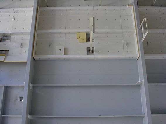 Figure 2
A view of several stiffeners on a ship, some having been insulated and some waiting to be insulated.
 Figure 3
Weld pin and cap.
 Figure 4
A 9.45-inch by 0.39-inch bulb stiffener currently used compared to a previously common 4-inch by 3-inch by ¼-inch angle stiffener. Note that the larger bulb stiffener, while obviously stronger, would also result in increased heat transfer from the ambient to the conditioned ship interior without a good insulation system that covers the bulb stiffeners.
 Figure 5
From the Technical and Research Bulletin 4-7, Thermal Insulation Report, The Society of Naval Architects and Marine Engineers, 1963
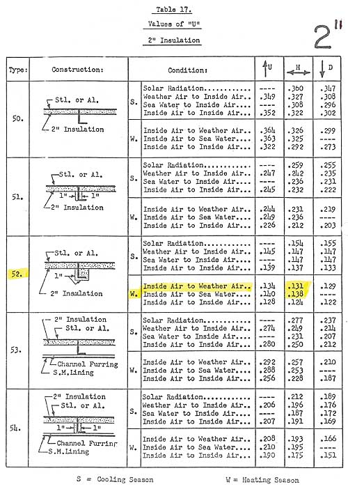 Figure 6
From the Technical and Research Bulletin 4-7, Thermal Insulation Report, The Society of Naval Architects and Marine Engineers, 1963
 Figure 7