Understanding Thermal Systems: Industrial Refrigeration Systems
The June issue of Insulation Outlook featured a column on basic cooling systems and, in particular, the vapor-compression cooling cycle. That discussion is continued in this month’s column by considering various industrial refrigeration systems where mechanical insulation is utilized extensively.
The basic vapor-compression cycle (Figure 1) requires 4 components: a compressor, condenser, expansion valve, and evaporator. The compressor (usually powered by an electric motor providing the work, W) compresses the refrigerant to a high pressure and high temperature. The refrigerant then flows to the condenser, which is a heat exchanger where heat (QH) is rejected to the environment (by air and/or water cooling) and the refrigerant is condensed to a liquid. The hot liquid refrigerant then passes through an expansion valve, where the refrigerant expands to a low pressure and a low temperature. The cold refrigerant then flows through another heat exchanger, called the evaporator, where it absorbs heat (QL) and boils back into a vapor on its way back to the compressor. During its circuit around the system, the refrigerant picks up heat at the evaporator and rejects that heat (along with the energy added by the compressor) at the condenser.
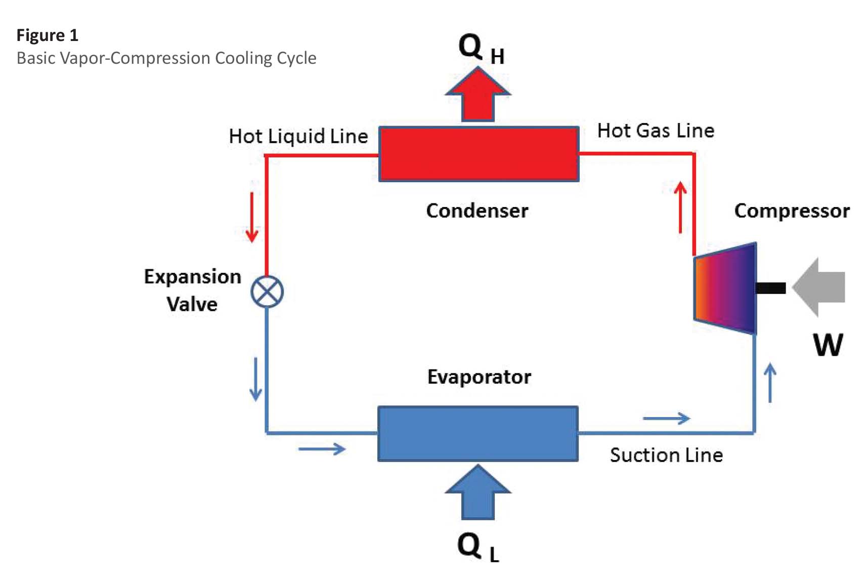
Insulation is typically used on the suction lines (between the evaporator and compressor) to prevent condensation and to limit unwanted parasitic heat gains. Any heat gain to these suction lines will increase the amount of work required at the compressor. Hot gas lines on refrigeration systems generally do not require insulation since the object here is to reject heat to the environment. An exception is where the hot gas lines are accessible by personnel and are hot enough to cause burns. Another exception would be where hot gas lines run through conditioned space where heat loss would add to the cooling load. Hot liquid lines typically do not require insulation since, again, the objective here is to reject heat to the environment.
While this basic refrigeration cycle is used in millions of systems worldwide, industrial refrigeration systems often are significantly more complicated. There are a number of reasons for the added complexity. One factor is that, in industrial applications, large loads with long operating hours can justify the added complexity to improve operating performance. Also, cooling is often required at very low temperatures or at several differing temperatures. Industrial systems often employ multistage cooling where several compressors and multiple evaporators are utilized.
A typical multistage system is shown in Figure 2. This system has 2 compressors operating in series. The output of the first-stage compressor is passed to a vessel called a flash intercooler. The intercooler, which operates at an intermediate pressure and temperature, is configured so that the hot gas from the low-stage compressor is bubbled through liquid refrigerant. Some of this liquid is evaporated, and saturated vapor from the intercooler is fed to the second-stage compressor. Saturated liquid from the intercooler is expanded and fed to the low-temperature evaporator. The net effect is that the 2-stage cycle requires less work than a single-stage system with the same load and operating conditions. This means that the coefficient of performance (COP) will be higher for the multistage system. Another advantage of the multistage system is that refrigerant may be utilized to satisfy loads at the intermediate temperature (say, a cooler at 40°F), while the low-temperature evaporator might be used for a freezer at a low-temperature (say, 0°F). Note that the intercooler typically operates below ambient temperature and will require insulation. Cold liquid lines will also require insulation, particularly those upstream of any refrigerant pumps where cavitation could be an issue.
Industrial refrigeration systems often include a number of other vessels and auxiliary equipment serving various purposes. Liquid receivers are vessels that are located downstream of condensers and serve to receive and store the refrigerant charge. A suction accumulator or a suction trap is located between the low-stage evaporator and compressor, and prevents liquid refrigerant from entering the compressor. Low-pressure receivers are used in liquid overfeed systems to separate liquid from vapor and as storage. Suction accumulators and low-pressure receivers will typically operate at temperatures below ambient, and will require insulation to minimize condensation and limit parasitic heat gains.
Industrial refrigeration systems are an important segment of the air-conditioning and refrigeration industry. The systems are often large, complicated, and utilize large quantities of insulation. Additional information on these systems may be found in the references.
References
- ASHRAE, ASHRAE Handbook–Refrigeration, Atlanta, Georgia; ASHRAE (2014).
- Wilbert Stoecker, Industrial Refrigeration Handbook, New York, McGraw-Hill
Education (1998).