Insulation should always be installed per manufacturer’s recommendations. To reach out directly to NIA’s Metal Building Laminators for more information on how to install correctly, please visit NIA’s membership directory at www.insulation.org/membership and choose Laminator as the Member Type.
Areas of Installation
NIA Certified Faced Insulation® is used as a primary insulation in exterior walls and roofing systems of metal buildings. It is also used as an additional layer of insulation in metal re-roof applications on built-up roofs and single-ply commercial buildings.
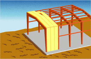
Facing

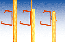
NIA Certified Faced Insulation® for metal buildings is supplied with the facing material wider than the fiber glass insulation. This allows for several necessary finishing details.
Wall Insulation—Lower Detail
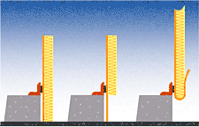
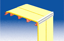
Roof Insulation—Edge Detail
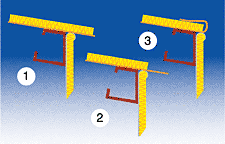
Stapling
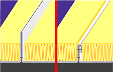
Rolling and stapling facing tabs is one of several closure methods used to assure moisture does not enter the insulation system through the seam.
Wall Insulation—Upper Detail
Completed Insulation System
Insulation Laminators
Metal buildings are traditionally insulated by a metal building erector with rolls of glass fiber insulation laminated to a flexible vapor retarder facing. These rolls are draped over the metal building frame with the vapor retarder towards the interior and then a metal skin is put on the outside which encloses the insulation and structure.
The Metal Building Insulation Laminator is a fabricator who prepares the metal building insulation for the erector by purchasing the insulation from the glass fiber manufacturer in desired “R” value thickness, and applies the vapor retarder to the insulation with adhesive using a laminating machine. The laminated rolls are then cut to specified lengths to fit the building and shipped directly to the job site.
Metal building laminators can assist in determining what insulation thicknesses, systems, etc. will meet ASHRAE 90.1 and other building codes. Information regarding retrofit and installation systems are also available from the laminators.
Installation of Filled Cavity Systems
Roof Insulation, Filled Cavity System
High Performance/Low U-Factor Double Layer Filled Cavity/Long Tab Banded roof insulation systems providing U-Factors ranging from 0.037 to 0.029 when installed in accordance with the supplier’s recommendations and the details below.
Section A: Materials Required:
- Fiberglass Insulation complying with the North American Insulation Manufacturing Association (NAIMA 202-96) specification or equal. Insulation details and orientation shall be:
- Bottom Layer (installed parallel to, and between the purlins):
- Fiber glass insulation faced on one side with a facing.
- The facing on the insulation shall be wide enough to provided extended tabs along each longitudinal edge of the insulation, capable of being overlapped and taped on top of the purlins without causing the insulation to pull away from the sides of the purlins.
- The facing shall have a strip of double sided tape applied to the inside surface along the outer edge of the extended tabs
- The insulation shall be supplied in widths to match purlin spaces and lengths approximately 2 feet longer than bay spaces.
- The faced fiber glass bottom layer composite shall have surface-burning characteristics not to exceed 25 flame spread and 50 smoke developed when tested in accordance with Underwriters Laboratories 723 or ASTM E84.
- See Section B for required fiber glass R-Values and Purlin Depths.
- Top Layer (installed perpendicular to the purlins):
- Unfaced supplied in rolls compatible with roof panel widths
- See Section B for required fiber glass R-Values
- Metal Banding—1” wide, installed under and perpendicular to purlins, 30” O.C.
- Banding Screws—3/4” hex-head TEK screws
- Thermal Blocks—1” thick, R-5 XPS.
Section B: Required Insulation R-Values for Specified U-Factors:
- 0.037 U-Factor
- Faced Bottom Layer—R-19
- Unfaced top layer—R-11
- Purlin Depth—8”
- 0.035 U-Factor
- Faced Bottom Layer—R-25
- Unfaced top layer—R-11
- Purlin Depth—8.5”
- 0.029 U-Factor
- Faced Bottom Layer—R-25
- Unfaced top layer—R-19
- Purlin Depth—10”
Roof Installation, Liner
Installation Fabric Liner Systems
When installing fabric liner systems, it is important to follow the manufacturer’s/suppliers instructions, as there are minor differences between fabric liner systems in the market. Next, review and inspect all materials relevant to the particular project
- Create a “platform” with banding under the purlins and over frames by securing the bands to the end wall frames and eave struts. There should be parallel and perpendicular banding. Refer to suppliers’ instructions for proper spacing.
- Locate the correct fabric liner panel for the bay to be installed. Stretch this panel from frame to frame and eave strut to eave strut or eave strut to splice point atop the banding platform under the purlin. Secure fabric in place temporarily with clamps. The liner panel will be wider than bay so as to allow the liner fabric to be adhered to the top of the primary structural framing.
- Make relief cuts in the liner fabric at each purlin so the fabric can be adhered to the top of the frames.
- Adhere the liner fabric to the top of the frames pulling the fabric taunt so as to remove as many wrinkles as possible.
- Attach the banding to each purlin with fasteners supplied with the liner system.
- Flange braces can be installed easily through the liner fabric. The building’s structural integrity must always be considered as attachment methods vary and need to be approved by the metal building manufacturer if different from their detail.
- Install the supplied NAIMA 202-96 fiber glass parallel between the purlins and perpendicular across the purlins as supplied for the particular project. Relief cuts to the fiber glass may be necessary at purlin bridging. The parallel fiber glass should lay flat against the liner fabric.
Wall Installation, Single and Double Layer in Cavity
Following are instructions for High Performance/Low U-Factor single and double layer filled cavity metal building wall insulation systems providing U-Factors ranging from 0.059 to 0.036 when installed in accordance with the supplier’s recommendations and the details below.
Section A: Materials Required- Single Layer – U-Factors 0.052 and 0.059:
- Foam thermal tape per Section C, should be applied to outside flange of girts
- Fiber glass insulation:
- When unfaced fiber glass is used, the insulation shall be installed on Insul-hold strips and completely fill the cavity between the wall girts.
- The interior surface of the insulation shall be covered with a facing or liner fabric
- When faced fiber glass is used, Insul-hold strips are not required.
- Facing seams shall be overlapped and sealed with tape or liner fabric may be used.
- Bands are to be installed perpendicular to the girts, 30” O.C.
- See Section C for insulation R-values and girt depths required to meet specified U-Factors
- The facing or liner shall have surface burning characteristics not to exceed 25 flame spread and 50 smoke developed when tested in accordance with Underwriters Laboratories 723 or ASTM E84.
Section B: Materials Required- Double Layer—U-Factors 0.039 to 0.036:
- R-5 foam thermal blocks or foam tape as specified in Section C
- Fiber glass insulation complying with the NAIMA 202-96 specification or equal. Insulation details shall be:
- Interior Layer (installed between the purlins):
- Fiber glass insulation either faced on one side with a facing or unfaced with a separate facing or liner.
- When the insulation is faced, the facing shall be wide enough to provided 1–3” wide tab along each longitudinal edge of the insulation, capable of being overlapped and taped to adjacent runs of insulation or the interior face of the girts.
- The facing may have a strip of double sided tape applied to the inside surface along the one or both longitudinal edges of the tabs
- Where applicable the insulation shall be supplied in widths to match purlin spaces.
- The faced fiber glass interior insulation composite shall have surface burning characteristics not to exceed 25 flame spread and 50 smoke developed when tested in accordance with Underwriters Laboratories 723 or ASTM E84.
- For unfaced fiber glass, the separate facing or liner shall have surface burning characteristics not to exceed 25 flame spread and 50 smoke developed when tested in accordance with Underwriters Laboratories 723 or ASTM E84.
- Install the liner fabric panel for the required bay stretching from frame to frame and floor to ceiling pulling the fabric taunt so as to remove as many wrinkles as possible and secure temporally in place with clamps.
- Adhere the liner fabric to the frames and base angle.
- Secure banding at each girt with fasteners supplied with the system. See manufacturer’s instructions for proper spacing.
- See Section C for insulation R-values and girt depths required to meet specified U-Factors.
- Outer Layer (installed perpendicular to the girts):
- Faced or Unfaced supplied in roll widths compatible with wall panel widths.
- If faced insulation is used, either the interior or exterior facing should be perforated to avoid a double vapor retarder condition. The side to be perforated is climate and occupancy dependant.
- See Section C for insulation R-values and girt depths required to meet specified U-Factors.
- Insul-Hold
- Metal Banding—1” wide, Installed perpendicular to girts, 30” O.C. on the interior side.
- Banding Screws—3/4" hex-head TEK screws
- Thermal Tape—3” wide x R-0.375 (Nominal 1/8”) or R-0.75 (Nominal ¼”) as indicted in Section C
- Foam Thermal Blocks—1”, R-53
Section C: Required Insulation R-Values for Specified U-Factors:
- 0.059 U-Factor
- Single Layer
- Unfaced R-25 Fiberglass
- Facing or Liner
- R-0.375 Foam Thermal tape (Nominal 1/8”)
- 8” Grits
- 0.052 U-Factor
- Single Layer
- Unfaced R-30 Fiberglass
- Facing or Liner
- R-0.75 Foam Thermal tape (Nominal 1/4”)
- 8” Grits
- 0.039 U-Factor
- Double Layer
- Interior—R-30 Faced Fiberglass (between girts)
- Exterior—R-16 Fiberglass (perpendicular to girts)
- Girt Depth—8”
- Double Layer
- 0.039 U-Factor
- Double Layer
- Interior—R-25 Faced Fiberglass (between girts)
- Exterior—R-10 Fiberglass (perpendicular to girts)
- R-3 Thermal Spacer Block
- Girt Depth—8”
- Double Layer
- 0.036 U-Factor
- Double Layer
- Interior—R-25 Faced Fiberglass (between girts)
- Exterior—R-16 Fiberglass (perpendicular to girts)
- R-0.375 Foam Thermal tape (Nominal 1/8”)
- Girt Depth—10”
- Double Layer
For more information on proper installation, contact a NIA member company.
