Mechanical Insulation Design Guide
Introduction
Within This Page
Installation of mechanical insulation is typically managed by experienced contractors who specialize in the mechanical insulation sector of the commercial, industrial and HVAC sectors of the construction industry. As with any successful construction project, the initial step is to read and understand the project specifications and drawings. The insulation contractor should be familiar with the objectives of the insulation job and be prepared to highlight and resolve any inconsistencies or errors in the specification. Often, specific insulation or accessory products are specified, and the insulation contractor must thoroughly understand the requirements for installing these products. The contractor must obtain and review the Safety Data Sheets (SDS) for all materials used on the project. Code compliance is generally the responsibility of the design professional, but knowledgeable insulation contractors should understand the code requirements in their localities and be able to help expedite the resolution of compliance issues. Sometimes there are conflicts between the specifications, the manufacturers' recommendations, and the code. Early identification and resolution of these conflicts is desirable.
NIA has launched a new training portal to expand its educational offerings. Numerous resources are available, including NIA's webinars; the Mechanical Insulation Installation Video Series; and other videos covering topics like safety, insulation business leadership and management, proper installation and thickness, and more. Visit www.niaeducationcenter.org to see the complete listing.
Pre-Work Considerations
Before starting work, insulation contractors must be aware of the specific location of the job. They must identify and plan to deal with any issues associated with the location. Efficient handling, movement, and storage of materials and personnel will be important, and planning will be required. In some cases, this may involve providing lifts or specialized jobsite vehicles. A clean, dry, and secure storage area for materials and equipment must be identified. Insulation materials that have become wet or damaged should not be installed and should be removed from the project.
Access to the work must be available. This will require close coordination with other trades to minimize congestion in the work area. The mechanical and/or general contractor will have this responsibility. Project readiness is sometimes an issue. Some products—such as adhesives, tapes, mastics, coatings, etc.—must be applied above a minimum temperature or in a given temperature range. The insulation contractor must be aware of such requirements and make the general and mechanical contractors (or others) aware of those limitations so they can provide the necessary environment to allow the work to be completed in a timely and efficient manner. In addition, the insulation contractor should highlight the potential for damage to the insulation system, completed or in process, by 1) other trades, 2) weather, or 3) other conditions beyond their control so that the mechanical or general contractor can take the appropriate steps to protect the work from damage.
Securing Methods
Mechanical insulation is installed in a variety of ways, depending on the application, the materials involved, and the environment. Installation methods can have a direct impact on the performance of the insulation system. A concern with all methods is to minimize the existence of thermal short circuits that can result in excessive heat loss for hot systems and excessive heat gain and possible condensation problems for cold systems. Metallic supports, hangers, and fasteners are common sources of thermal short circuits, and they should be used carefully. For systems involving large temperature differences, multiple layers of insulation allow the opportunity to stagger joints, thereby minimizing thermal shorts at through joints.
Pipe and Tubing
Small pipe and tubing can be insulated with cylindrical half-sections of rigid insulation or with preformed flexible material. Larger pipes can be insulated with flexible material or with curved, flat segmented or cylindrical half-, third-, or quarter-sections of rigid insulation. Fittings (valves, tees, crosses, and elbows) may use preformed fitting insulation, fabricated fitting insulation, individual pieces cut from sectional straight-pipe insulation, or insulating cements. Fitting insulations always should be equal in thermal performance to the pipe insulation.
The method of securement varies with the type of insulation, size of pipe, form and weight of insulation, and type of jacketing (i.e., field or factory applied). Insulation with factory-applied jacketing can be secured on small piping by utilizing the overlapping jacket, which usually includes an integral sealing tape (commonly called SSL for self-sealing lap). Large piping may require supplemental wiring or banding. Insulation on large piping that requires separate jacketing may be wired or banded in place; and the jacket is cemented, wired, or banded, depending on the type. Insulation with factory-applied metal, membrane, or PVC jacketing is secured by specific design of the jacket and its joint closure system.
Several valuable references provide guidance on installation details. The Midwest Insulation Contractors Association’s North American Commercial and Industrial Insulation Standards manual, formerly known as "the MICA Manual," provides detailed illustrations of various techniques for applying mechanical insulations. The Insulation Practices section of the Process Industry Practices (PIP) provides guidance aimed specifically at industrial work.
Insulating Pipe Hangers
All piping is held in place by hangers or supports. Selection and treatment of pipe hangers and supports can negatively impact the thermal performance of an insulation system. Additionally, the choice of hangers can influence the ability to seal the vapor retarder on cold systems. Thus, it is important that the insulation contractor review the specifications and drawings to understand the hangers that will be used and to verify that sufficient physical space is maintained to allow for the required thickness of insulation.
A typical ring or line size hanger has been commonly used on above-ambient lines at moderate temperature. However, that practice provides a thermal short circuit through the insulation, and the penetration is difficult to seal effectively against water vapor, so it is not recommended for cold systems.
Pipe shoes are used for hot piping of large diameter (heavyweight piping) and where significant pipe movement is expected. The design allows for pipe movement without damage to the insulation or the finish. The design is not recommended for below-ambient applications because of the thermal short circuit created as well as difficulty in vapor sealing.
Figure. 1 Insulating Pipe Hangers
©American Society of Heating, Refrigerating and Air-Conditioning Engineers, Inc.
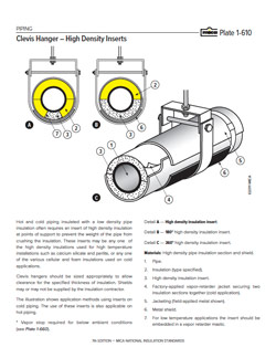
A better solution is to use oversized (as opposed to line-sized) clevis hangers, which are sized to allow clearance for the specified thickness of insulation, and avoid the short circuit associated with ring and shoe hangers. Shields (or saddles) spread the load from the pipe, its contents, and the insulation material over an area sufficient to support the system without significantly compressing the insulation material. The appropriate saddle length will depend on the weight of the pipe and contents. Suitable high-density inserts often are required to prevent the weight from crushing the insulation. (Reference: ANSI/MSS SP-69-2003 Pipe Hangers and Supports – Selection and Application)
For vertical piping, welded or bolted-on support rings are often required. Allowance for contraction or expansion may be needed, depending on the service temperature requirements and the insulation materials specified.
Flanges and valves in piping runs require either removable reusable fabricated fitting covers (see Materials and Systems, the Removable Reusable Covers section) or oversizing in the field.
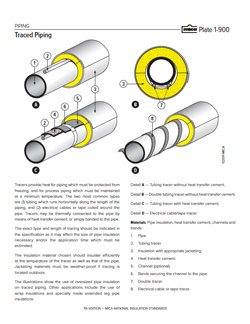
Heat tracing is often specified where piping must be protected from freezing or where process piping must be maintained at a minimum temperature. Tracing may be electrical cables or tape wrapped around the pipe, or in some cases tubing for carrying steam that runs down the length of the pipe. This may require oversizing the pipe insulation to accommodate the tracing.
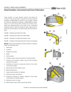
Tanks, Vessels, and Equipment
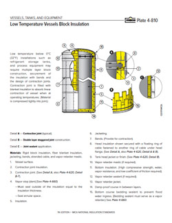
Flat, curved, and irregular surfaces, (e.g., tanks, vessels, boilers, and breechings) are normally insulated with flexible or semirigid sheets or boards, or rigid insulation blocks fabricated to fit the specific application. Tank and vessel head segments may be curved or flat and cut to fit in single piece or segments per ASTM C450. Head segments must be cut to eliminate voids at the head section, and in a sufficient number of pieces to minimize joints. Prefabricated flat head sections should be installed in the same number of layers and thickness as the vessel walls, and void areas behind the flat head should be filled with packable insulation. Typically, the curved segments are fabricated to fit the contour of the vessel surface in equal pieces to go around the vessel with a minimum number of joints. Because no general procedure can apply to all materials and conditions, manufacturers' specifications and instructions must be followed for specific applications.
Insulations are secured in various ways, depending on the form of insulation and contour of the surface to be insulated. Flexible insulations can be adhered to tanks, vessels, and equipment using contact adhesive, pressure-sensitive adhesives, or other systems recommended by the manufacturers. Rigid or semirigid insulations on small-diameter, cylindrical vessels can be prefabricated and adhered or mechanically attached, as appropriate. On larger cylindrical vessels, angle iron insulation support rings can supplement banding. For horizontal tanks, slotted angle iron may be run lengthwise on the cylinder at intervals around the circumference to secure and avoid an excessive length of banding. The use of expansion springs is recommended where tanks are subject to significant expansion and contraction.
Rigid and semirigid insulations can be secured on large flat and cylindrical surfaces by banding or wiring, and they can be supplemented by fastening with welded studs with speed washers at frequent intervals.
Ducts
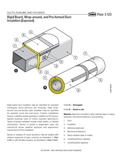
Exterior rigid or flexible duct insulation can be attached with adhesives, supplemental pins and clips, or wiring or banding. Individual manufacturers of these materials should be consulted for their installation requirements. Flexible duct wraps normally do not require attachment, except on bottom duct panels more than 24" wide. For larger ducts, pins placed at a maximum spacing of 24" or less are sufficient. Internal liners are attached with adhesive and pins, in accordance with industry standards. For fibrous glass duct liners, follow the NAIMA Fibrous Glass Duct Liner Standard. For other materials, consult the manufacturers.
Finishes
Insulation systems are usually (but not always) finished to protect the insulation or for appearance purposes. Finishes are generally categorized by the type of protection required (e.g., weather barriers, vapor retarders, mechanical abuse coverings, or appearance coverings). Some insulation products use factory-applied coverings that may combine the finish and securement functions. Installation of these products should follow the manufacturers’ recommendations. In other cases, the finish is installed in the field.
Metal jacketing (or lagging) may be aluminum, stainless steel, or coated steel. Metal jacketing products are available in a number of finishes. Jacketing may be secured by rivets, screws, or banding. For cold-service applications, metal jacketing is typically installed over the vapor retarder, and care should be taken not to disturb or puncture the vapor retarder with screws or rivets. Overlaps should be positioned to shed water, and longitudinal laps should be wide enough to provide weatherproofing. It is recommended the metal be pre-rolled to snugly fit the circumference of the insulation to prevent fish-mouthing along the longitudinal lap. A 1/2" to 1" hem along the longitudinal lap may be added to the jacketing to further prevent fish-mouthing and to give it a safety edge. All overlaps should be a minimum of 2", preferably 3" on larger diameters.
PVC jackets should be cut and curled when applied to insulated pipe diameters of 8" or smaller; above 8" they can be cut on site. The laps can be sealed with appropriate adhesive to make a moisture-tight jacket. PVC adhesive should be used only on thicknesses of 20 mm or more.
Laminates come in a variety of designs and thicknesses, and they are sometimes factory applied. For field application, consult the manufacturer's instructions.
Mastics are sometimes specified as a finish material, often in conjunction with reinforcing fabric or mesh. Application should follow the manufacturer's recommendations. The contractor should be aware that both weather-barrier and vapor-retarder mastics are available.
Special Considerations
A number of special installation considerations may come into play, depending on the job, as described below.
Access for inspection. Some critical systems require access for periodic inspection. In these cases, removable insulation covers or inspection ports are specified, particularly at valves, fittings, and flanges, where leakage is most likely to occur.
Adequate space for insulation thickness. Allowance for adequate space for insulation is an issue with many installations. This is a design issue and should be addressed at the design phase of the project.
Mechanical protection. Protecting the insulation from physical abuse should be considered as part of the insulation system design, but often it is overlooked. The design team should highlight locations where high traffic or activities could damage insulation. These conditions may suggest the use of additional protection (metal jacketing, PVC jacketing, and/or walkways).
Startup precautions. Some insulation materials require specific procedures at project startup. This could involve heat-up schedules for high-temperature applications. There also may be requirements for specific personal protective equipment due to the potential for out-gassing. The appropriate material safety data sheets should be reviewed for specifics.
Fire-resistant assemblies. Some specifications will require fire-resistant ratings, usually in the form of "hourly ratings" for wall, ceiling, or through penetrations. Requirements for "grease duct" insulation fall into this category. These fire-resistant ratings generally refer to listed assemblies that have been tested by nationally recognized testing laboratories. It is important to understand that the insulation used in these assemblies is only one of many components in the assembly, and compliance with the hourly rating will depend on installation per the requirements of the listing. For more information, see Design Objectives – Fire Safety.
Inspection and Maintenance
Insulation systems, like all mechanical systems, require periodic inspection and maintenance. While inspection and maintenance are the responsibility of the facility owner, the fact is that most insulation systems are frequently ignored. With time, they can become damaged and, if not repaired or replaced in a timely and proper manner, they can become ineffective and lead to other potential problems, including (but not limited to) personnel and process safety concerns and the development of corrosion under insulation (CUI) and mold.
Corrosion occurs in carbon steels and 300-series stainless steels. On the carbon steels, it manifests as generalized or localized wall loss. With the stainless pipes, it is often seen as pitting and corrosion-induced stress cracking. Though failure can occur across a broad band of temperatures, corrosion becomes a significant concern at the temperatures listed below. The Association for Materials Protection and Performance (formerly NACE International) has concluded that CUI is more prevalent in the service temperature range of 25°F (-4°C) to 350°F (175°C) for carbon steel, and 120°F (50°C) to 350°F (175°C) for austenitic or duplex stainless steel.
Insulation contractors can play a key role in facilitating regular inspection and maintenance programs and in addressing the need for insulation inspection. The NIA’s Thermal Insulation Inspector Certification™ Program—a two-part, 4-day course— educates participants on how to evaluate installation work and determine whether it is compliant with mechanical insulation specifications. Upon completing the course and receiving a passing grade on final exams, participants become NIA Certified Thermal Insulation Inspectors. (For a complete list of NIA Certified Thermal Insulation Inspectors, please click here.)
Failure to perform inspection and timely maintenance carries a number of risks. Missing or damaged insulation results in increased heat loss or gain, translating into economic losses and potentially CUI, personnel safety, and other concerns. For outdoor systems, damaged or missing weather barriers can allow rainwater entry, which can compromise the effectiveness of the insulation system and lead to many other concerns. On cold systems, damaged vapor retarders will lead to increased water vapor intrusion, which can reduce insulation effectiveness, increase rates of corrosion, and increase the potential for mold growth. If inspection reveals missing or damaged insulation, repairs should be scheduled as soon as possible. This is particularly true for cold systems, where water vapor intrusion can rapidly spread.
At a minimum, insulated areas should be inspected annually. Inspection of the external surface should include looking for signs of cracking, distortion, damage, corrosion, and evidence of hot spots on high-temperature systems or condensation or ice buildup on low-temperature systems. When necessary, external finish should be removed to enable inspection of the insulation and attachments. Infrared video cameras can be useful for inspection and should be considered for both post-startup inspection and ongoing insulation maintenance.
When removal and replacement is indicated, re-insulation should be performed in the same manner as the original installation unless: 1) The nature of the damage indicates that the system was improperly insulated, or 2) the materials originally used are now outdated. Damaged insulation should be torn back to undamaged and dry material. Care should be taken in removal of existing insulation to minimize damage. Temporary protection for adjacent insulation may be required to prevent damage while repairs are underway.
Risk Assessment Discussion
This risk assessment discussion has been designed specifically for the mechanical insulation applications defined in Mechanical Insulation Design Guide (Design Guide).
There are risks associated with not maintaining a mechanical insulation system in a timely and effective manner. Those risks—and the severity of those risks—vary, depending upon the use and service temperature of the operating system on which the insulation is installed, the surrounding environment, the ambient conditions, the extent of any damage to the insulation system, the insulation system design, the quality of the installation, the timeline of correcting any damage, and other conditions that may be unique to the area in question.
The following risks could result if timely and effective mechanical insulation system maintenance is not performed. Note that they may not apply to all situations, and multiple risks could occur simultaneously or in varying order.
- Increased energy cost
- Increase in greenhouse gas emission
- Degradation of process/production quality and increased costs
- Development of CUI
- Development of condensation and/or ice (depending on the service temperature)
- Potential development of mold or mildew
- Personnel safety risks
- Lowered personnel productivity
- Diversion of time and attention from other initiatives
- Poor facility appearance
- Negative impacts to equipment life and operational efficiency
- Increased life-cycle cost
- Negative effect on sustainability objectives
- Lower/Missed return on investment
Company and individual levels of risk tolerance vary; however, the negative impacts of not timely and correctly maintaining a mechanical insulation system are real and should not be overlooked or underestimated. Lists of inspection benefits are available for the following disciplines:
Maintenance Checklist
Like the risk assessment discussion above, this checklist has been designed for the mechanical insulation applications defined in the Design Guide.
The checklist is provided as a simple guide for individuals evaluating the condition of an installed mechanical insulation system. It is not intended to be all inclusive or to provide sufficient information to allow anyone not certified as a Thermal Insulation Inspector—regardless of experience level—to serve as an inspector of mechanical insulation systems.
Upon observing any of the following conditions, a maintenance request/action plan should be implemented to: 1) assess the degree of damage, and 2) repair and/or replace the damaged area of the insulation system to prevent further damage and avoid further risk. The listed content does not appear in a particular order of importance or priority.
- Damage to or wearing of the outer jacketing/finish of the insulation system (Damage could be caused by mechanical abuse, negligence, weather, or simply could occur over time)
- Protrusions in the insulation system that are not sealed, or sealant that is missing or damaged
- Penetrations to the insulation system that are not sealed
- Insulation missing (for whatever reason)
- Insulation removed and not yet replaced
- Insulation supports that are failing or appear not to be working correctly
- Ice, mold, or mildew on/in the insulation system
- Condensation
- Discoloration of the insulation system (other than by dirt)
- "Fish mouthing" of the outer jacketing seams
- Missing or loose insulation system securements
- Sagging or pulling away of the insulation system
- "Hot spots" in the insulation system
- Insulation system appears wet
- Opening of joints in the insulation
- Expansion or contraction joints not functioning correctly
- Insulation system in an environment or service different from the original design for the insulation system
General Guideline for the Repair and Replacement of Below-Ambient Mechanical Insulation Systems for Areas in Need of Repair or Substrate Inspection
(This guideline does not apply to cryogenic applications; however, some of the general considerations and other information may be applicable.)
This guideline has been developed specifically to provide general guidance for the repair and/or replacement of mechanical insulation systems due to damage incurred from any number of sources, and for procedures for "non-destructive" testing of the substrate beneath insulation systems operating below ambient temperature.
The physical penetration of any intact and operating insulation system should be viewed as destructive and avoided if possible. Other forms of non-invasive inspection that do not require penetration of the insulation system should be investigated before proceeding with any procedure that requires penetration of the insulation system.
Consideration should be given to the need to penetrate the insulation system for substrate inspection during the insulation system design phase, including addressing the potential use of inspection ports, drains, or vents, and identifying the location of inspection points.
If the insulation system is being repaired due to damage, it is recommended that substrate inspection be conducted at that time, rather than penetrating an intact and performing insulation system.
This guideline is intended to be generic and general in nature. The facility owner and/or insulation system design engineer may have specific recommendations beyond the scope of this guideline. In addition, the insulation, vapor retarder, protective covering, and system component manufacturers should be contacted for their repair and replacement recommendations.
Insulation systems, like all mechanical systems, require periodic inspection and maintenance. Failure to perform inspection and timely maintenance carries a number of risks. While inspection and maintenance are the responsibility of the facility owner, the fact is that most insulation systems are frequently ignored. With time, insulation systems can be damaged by a variety of sources. If not repaired or replaced in a timely and proper manner, the systems can become ineffective or, worse yet, can contribute to the degradation of the mechanical system.
Because inspection and maintenance of mechanical insulation systems is in most cases the responsibility of facility owners, they need to understand the value of being proactive in having a meaningful, ongoing maintenance program; as well as being appropriately reactive as the need or requirement presents itself. Some owners employ a combination of both approaches, which also may vary from year to year.
The key is having a consistent approach to the inspection process. Unfortunately, the importance of timely and proper repair of mechanical insulation systems is often overlooked and undervalued.
GENERAL CONSIDERATIONS AND PREPARATION
- All areas in which the protective covering and/or vapor retarder has been penetrated, and any other areas that potentially allow for the entrance of moisture or other containments, should be examined in a timely manner to determine the extent of any damage to the total insulation system. The required repairs/replacement should be executed in a timely and proper manner by experienced insulation contractor.
- Prior to penetrating the system and insulation removal, careful planning is required in order to ensure that the inspection is as minimally invasive as possible, and repair and replacement accomplished in a correct and timely manner.
- Prior to removing or repairing the insulation system, verify the type of materials to be removed and/or repaired. If there are any questions pertaining to those materials, contact the respective manufacturer(s) or others, as necessary. Review the appropriate safety guidelines and work practices for the materials to be removed, repaired, and installed.
- Contact the insulation, vapor retarder, protective covering, and other system component manufacturers for specific repair recommendations for the insulation system and operating conditions involved. If the system is operating during the inspection process, consideration should be given to personnel protection requirements.
- Have proper tools, supplies, and sufficient repair and/or replacement materials on hand to effect repairs to the insulation system immediately, especially following the system being penetrated for inspection. Ideally, the insulation should be removed immediately—15 minutes at most—before the inspection, the repair procedure begun immediately after the inspection, and repairs completed as soon as possible.
- Repairs to the system are to be made using the same materials and insulation thickness used in the original system, unless otherwise approved.
- For systems operating below 0°C (32°F), a deicer such as methanol may be needed to remove ice buildup if the repair is not done immediately. In addition to methanol, ethylene glycol, propylene glycol, and vehicle antifreeze can be used to remove or potentially prevent the formation of ice for a short period of time. Each of these materials has various environmental, health, and safety issues that should be considered prior to use. When utilizing any of these materials, care should be taken to minimize contact with the remaining insulation system.
- Repairs to the insulation system should be made by an experienced insulation contractor immediately after the inspection is completed.
- Penetration of the insulation system should never be made in inclement weather or when inclement weather is anticipated before the repair can be completed.
- If possible, penetration and repairs should be made while the operating system for the area in question is not in operation. Repairs made while the system is in service are difficult and may not yield the expected long-term results.
- Penetration of the insulation system could void insulation system or material warranties, written or implied. The insulation contractor and material manufacturers should be contacted before proceeding with any invasive inspection process. In addition, failure to follow the recommended repair guidelines of the respective contractor, material manufacturers, etc. also could void any and all insulation system warranties, written or implied.
- Penetrating a below-ambient insulation system and not properly and timely repairing the area could create damage to an extended area of the insulation system; shorten the life of the insulation system; and create many other concerns such as, but not limited to, substrate corrosion, condensation, safety-related issues, etc.
- Where possible, penetrations should be made on the bottom 180 degrees of all horizontal surfaces and on the very bottom if possible. If penetrations are made on the top of a vessel or other horizontal surface that is exposed to the elements, the additional risk associated with that penetration should be understood by all parties and care taken accordingly.
- Consideration should be given—where possible, given the operating temperature and environment—to the installation of devices to allow the escape or venting of any moisture that may have entered (or will enter) the system, including inspection ports to facilitate future substrate inspection.
CONSIDERATIONS FOR INSULATION REMOVAL
- Removal of the insulation from the area to be inspected should be done by experienced craft personnel.
- Care must be exercised during the insulation removal process to avoid damaging the insulation system beyond that which is required for the repair or inspection.
- Confirm the method and location of disposal with the insulation manufacturers and the appropriate authorities.
INSULATION SYSTEM REPAIR
- The insulation system should be removed to the extent required to ensure all damaged insulation is removed. If the insulation is wet, it is good practice to remove it to the next dry joint in the insulation. This approach is more readily employed if the system is not in service. All exposed edges of the remaining insulation should be cut or sanded as needed to create a clean and straight edge.
- Working outward on multilayer insulation systems, remove an additional 2"–4” wide strip of insulation from successive insulation layers around the perimeter of the inspection area so that the repair joints will be staggered when the insulation is replaced.
- Measure the exposed area and cut replacement insulation to fit the exposed area. The insulation should be tightly installed, friction fit when possible.
- Just prior to replacement of the insulation, wipe the exposed area down with dry rags to remove all dirt or other contaminants, and any condensation.
- For totally adhered systems, replace the insulation and seal the joints using the adhesive and joint sealer recommended by the respective manufacturer.
- For mechanically attached systems, replace the insulation and seal the joints using the joint sealant recommended by the respective manufacturer.
- On multilayer systems, the inner layers are to be replaced without joint sealant and the joints of the outer layer sealed using the joint sealant recommended by the respective manufacturer.
- The vapor retarder shall be installed as recommended by the respective manufacturer.
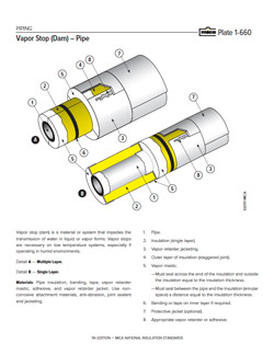
- Vapor stops (vapor dams) should be installed on all sides of the replaced insulation to guard against further damage to the adjacent areas.
- If applicable, replace the insulation protective covering with materials that match those used for the original installation and as recommended by the covering manufacturer. Ensure the covering is installed to shed water and not damage the vapor retarder.
- Perform a full inspection of the damaged area during the removal and replacement or repair process, and upon completion of the work, and make adjustments as necessary.
General Guideline for the Repair and Replacement of Above-Ambient Mechanical Insulation Systems for Areas in Need of Repair or Substrate Inspection
This guideline has been developed specifically to provide general guidance for the repair and/or replacement of mechanical insulation systems due to damage incurred from any number of sources, and for procedures for "non-destructive" testing of the substrate beneath insulation systems operating above ambient temperature.
The physical penetration of any intact and operating insulation system should be viewed as destructive and avoided if possible. Other forms of non-invasive inspection that do not require penetration of the insulation system should be investigated before proceeding with any procedure that requires penetration of the insulation system.
Consideration should be given to the need to penetrate the insulation system for substrate inspection during the insulation system design phase, including addressing the potential use of inspection ports, drains, or vents, and identifying the location of inspection points.
If the insulation system is being repaired due to damage, it is recommended that substrate inspection be conducted at that time, rather than penetrating an intact and performing insulation system at a later date.
This guideline is intended to be generic and general in nature. The facility owner and/or insulation system design engineer may have specific recommendations beyond the scope of this guideline. In addition, the insulation, weather barrier/protective covering, and system component manufacturers should be contacted for their repair/replacement recommendations.
Insulation systems, like all mechanical systems, require periodic inspection and maintenance. Failure to perform inspection and timely maintenance carries a number of risks. While inspection and maintenance are the responsibility of the facility owner, the fact is that most insulation systems are frequently ignored. With time, insulation systems can be damaged by a variety of sources. If not repaired or replaced in a timely and proper manner, the systems can become ineffective or, worse yet, contribute to the degradation of the mechanical system.
Because inspection and maintenance of mechanical insulation systems is in most cases the responsibility of facility owners, they need to understand the value of being proactive in having a meaningful, ongoing maintenance program; as well as in being appropriately reactive as the need or requirement presents itself. Some owners employ a combination of both approaches, which also may vary from year to year.
The key is having a consistent approach to the inspection process.
GENERAL CONSIDERATIONS AND PREPARATION
- All areas in which the protective covering and/or weather barrier has been penetrated, and any other areas that potentially allow for the entrance of moisture or other contaminants, should be examined in a timely manner to determine the extent of any damage to the total insulation system. The required repairs/replacement should be executed in a timely and proper manner by experienced insulation contractor.
- Prior to penetrating the system and insulation removal, careful planning is required in order to ensure that the inspection is as minimally invasive as possible, and repair and replacement accomplished in a correct and timely manner.
- Prior to removing or repairing the insulation system, verify the type of materials to be removed and/or repaired. If there are any questions pertaining to those materials, contact the respective manufacturer(s) or others, as necessary. Review the appropriate safety guidelines and work practices for the materials to be removed, repaired, and installed.
- Contact the insulation, weather barrier, protective covering, and other system component manufacturers for specific repair recommendations for the insulation system and operating conditions involved. If the system is operating during the inspection process, consideration should be given to personnel protection requirements.
- Have proper tools, supplies, and sufficient repair and/or replacement materials on hand to effect repairs to the insulation system immediately, especially following the system being penetrated for inspection. Ideally, the insulation should be removed immediately—15 minutes at most—before the inspection, the repair procedure begun immediately after the inspection, and repairs completed as soon as possible.
- Repairs to the system are to be made using the same materials and insulation thickness used in the original system, unless otherwise approved.
- Repairs to the insulation system should be made by an experienced insulation contractor immediately after the inspection is completed.
- Penetration of the insulation system should never be made in inclement weather or when inclement weather is anticipated before the repair can be completed.
- If possible, penetration and repairs should be made while the operating system for the area in question is not in operation. Repairs made while the system is in service are difficult and may not yield the expected long-term results.
- Penetration of the insulation system could void insulation system or material warranties, written or implied. The insulation contractor and material manufacturers should be contacted before proceeding with any invasive inspection process. In addition, failure to follow the recommended repair guidelines of the respective contractor, material manufacturers, etc. also could void any and all insulation system warranties, written or implied.
- Penetrating an above-ambient insulation system and not properly and timely repairing the area could create damage to an extended area of the insulation system; shorten the life of the insulation system; and create many other concerns such as, but not limited to, substrate corrosion, condensation, safety-related issues, etc.
- Where possible, penetrations should be made on the bottom 180 degrees of all horizontal surfaces, or on the very bottom if possible. If penetrations are made on the top of a vessel or other horizontal surface that is exposed to the elements, the additional risk associated with that penetration should be understood by all parties and care taken accordingly.
- Consideration should be given—where possible, given the operating temperature and environment—to the installation of devices to allow for the escape or venting of any moisture that may have entered (or will enter) the system, including inspection ports to facilitate future substrate inspection.
CONSIDERATIONS FOR INSULATION REMOVAL
- Removal of the insulation from the area to be inspected should be done by experienced craft personnel.
- Care must be exercised during the insulation removal process to avoid damaging the insulation system beyond that which is required for the repair or inspection.
- Confirm the method and location of disposal with the insulation manufacturers and the appropriate authorities.
INSULATION SYSTEM REPAIR
- The insulation system should be removed to the extent required to ensure all damaged insulation is removed. If the insulation is wet, it is good practice to remove it to the next dry joint in the insulation. This approach is more readily employed if the system is not in service. All exposed edges of the remaining insulation should be cut or sanded as needed to create a clean and straight edge.
- Working outward on multilayer insulation systems, remove an additional 2"–4” wide strip of insulation from successive insulation layers around the perimeter of the inspection area so that the repair joints will be staggered when the insulation is replaced.
- Measure the exposed area and cut replacement insulation to fit the exposed area. The insulation should be tightly installed, friction fit when possible.
- Just prior to replacement of the insulation, wipe the exposed area down with dry rags to remove all dirt or other contaminants.
- For mechanically attached systems, replace the insulation and respective weather barrier/protective covering as recommended by the respective manufacturer.
- On multilayer systems, the inner layers are to be replaced without joint sealant, unless otherwise recommended by the respective facility owner and/or manufacturer.
- If applicable, replace the insulation protective covering with materials that match those used for the original installation and as recommended by the covering manufacturer. Ensure the covering is installed to shed water and not damage the vapor retarder.
- Perform a full inspection of the damaged area during the removal and replacement or repair process, and upon completion of the work, and make adjustments as necessary.
Installation Plate Examples
PIP INIC0008 - View enlarged plate