A Discussion of Changes to ISO15665:2023-12 Acoustics—Acoustic Insulation for Pipes, Valves, and Flanges
ISO 15665:2023 Acoustics — Acoustic Insulation for Pipes, Valves, and Flanges is the international standard governing the determination and certification of acoustic insulation insertion loss for pipes, valves and flanges. This second edition of ISO15665 (2023–12) cancels and replaces the first edition (ISO15665:2003) and incorporates the Technical Corrigendum ISO15665:2003/Cor.1:2004.
The revision was tasked with updating the standard to align with improvements in material technology and techniques; incorporate considerations in the thermal credit of acoustic materials in thermal-acoustic systems and in selection of materials where corrosion under insulation (CUI) is a concern; and amalgamate the classification of D2 and D3 insertional loss defined in the Shell DEP 31.46.00.31.
This article will present the following updates and revisions:
- Acoustic Insertion Loss
- Understanding the Overall Noise Reduction
- System Constructions and Testing
- Removeable Acoustic Jackets
- Determination of Infield Sound Insertion Loss (Sound Pressure)
Acoustic Insertion Loss
The acoustic insertion loss provided by a pipework insulation material or system is the difference in the sound power level radiated from a noise source before and after the application of the acoustic insulation for any octave or one-third-octave frequency band.
Clause 4 of the standard defines the classification of acoustic insulation for various pipe diameters:
- Less than 300 mm outside diameter,
- Greater than or equal to 300 mm diameter, but less than 650 mm;
- Greater than or equal to 650 mm diameter, but less than 1,000 mm.
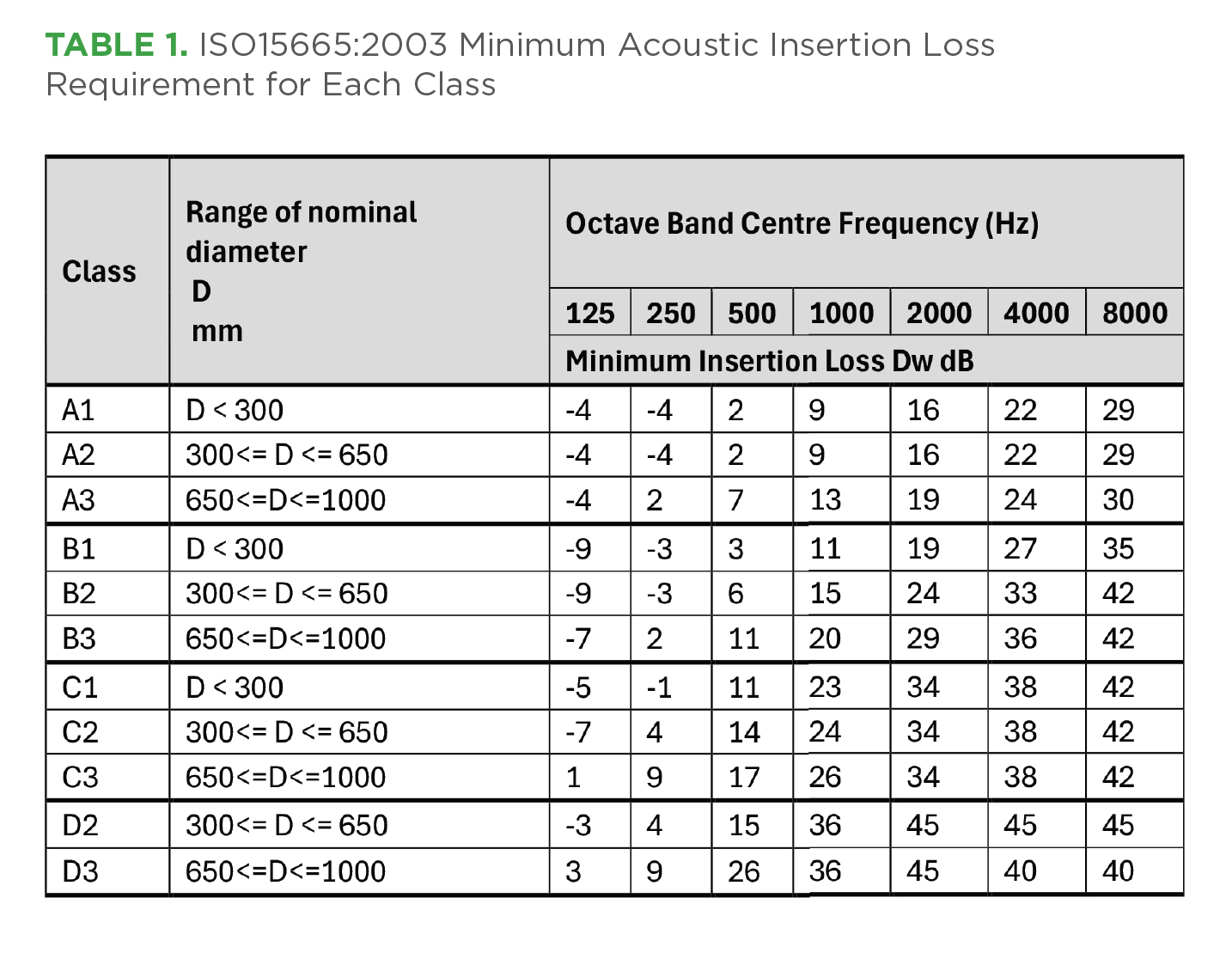
The 2003 version of the standard presented three classifications for each of these diameter ranges, Class A-C, with prescribed acoustic insertion loss at each octave band frequency between 125Hz to 8,000Hz. Multinational oil and gas company, Shell, then produced an additional insertion loss classification for diameters (2) and (3), Class D, in their Design Engineering Practice (DEP) document DEP 31.46.00.31. Between the issuance of these original documents and the issuance of the 2023 revision of the standard, the four classes have been referenced regularly within industry. The 2023 revision has now incorporated the Shell DEP classifications into the main standard so that all four are now held in ISO15665:2023. The updated insertion loss classifications and requirements are presented in Table 1.
To satisfy a given classification, the insertion loss of all seven octave bands must exceed or be equal to the insertion loss values provided in Table 1. Any insulation system that does not fully satisfy the above requirements would be designated as “unclassified.”
Understanding the Overall Noise Reduction
To understand the effectiveness of an acoustic insulation system on a noise source, the overall reduction can only be undertaken for the octave band frequency spectrum of the noise. It is noted that, where possible, the actual sound level frequency spectrum of the pipe under consideration should be obtained. The insertion loss at each frequency of a given insulation system can then be subtracted from the corresponding pipe sound level frequencies. Logarithmically adding these attenuated octave band frequency levels will then provide the predicted insulated pipe sound level.
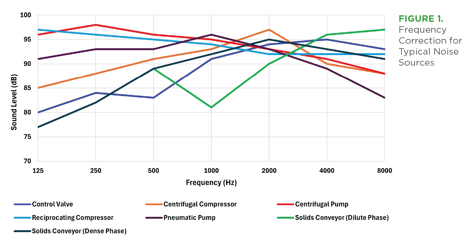
However, the determination of the actual pipe sound levels in octave bands is often not possible. ISO15665 therefore provides generic octave band frequency spectra for pipes attached to typical industrial sound sources. The 2023 revision of the standard has extended the types of sound source to now include solids conveyor pipes in both the dilute and solids phases.
If the overall noise level of a pipe is known, a correction is applied for the different sound source at each octave band frequency. Figure 1 presents the generic, expected noise source frequency spectra for typical noise sources often associated with pipe noise. In this example, the overall sound level for each source is 100 dBA. As can be seen, the frequency spectrum varies significantly with each sound source. The selection of acoustic insulation will therefore depend on the insertion loss performance at each octave band frequency of the insulation system, presented in the test certificate for that system, and the noise source spectrum.
To highlight the range of reduction that can be achieved with a simple classification requirement, Table 2 provides a comparison. If we consider the noise attenuation that could be achieved with an insulation system that equals the standard Class C2 insertion loss, for each of these noise sources in the standard, then apply the calculation in Clause 5 of the ISO15665 standard, the following results are predicted.
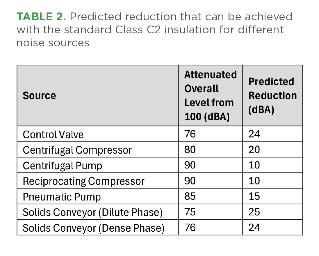
The standard provides a typical performance and reduction of the noise sources. However, it is recommended that the actual noise source data is determined and used in conjunction with the certified insertion loss performance of specific material systems to predict the achievable noise reduction more accurately for a given situation.
System Constructions and Testing
With more material systems now available for acoustic pipework insulation, it is often not just the acoustic performance that needs to be considered. With material systems also having to account for thermal performance and address concerns around CUI, the standard revision has made several changes to reflect these topics. These changes include the following:
- Additional emphasis placed on the requirement for insertion loss testing for determining acoustic performance of pipework insulation systems.
- Introduction of flexible elastomeric foam and aerogel blankets.
- Removal of airflow resistivity for porous layer, as this parameter is not necessary for all material systems.
- Change of previous Clause 9: “Acoustic insulation constructions that meet the insulation class requirements” into Annex A to update and expand the use of various, newer material system constructions.
- Introduction of CUI as a material/system selection requirement.
- Consideration of the thermal performance of acoustic materials for thermal-acoustic systems.
Since the original standard release in 2003, material technologies have improved. In 2003, the primary materials of choice, and for the attainment of the acoustic insertion loss curves, were mineral wool and steel. It was noted that other materials could be suitable for outer layers, additional layers, vibro-acoustic seals, and porous materials. Many of the original listed materials have been retained, and two materials were added: flexible elastomeric foams (FEF) and aerogel blankets.
Both FEF and aerogel blankets have allowed for a significant reduction in the thickness of acoustic insulation while still maintaining and often exceeding the classic insertion loss performance of mineral wool systems. The original version of the standard outlined material characteristics for a mineral wool “porous” layer to maximize the airborne acoustic absorption and minimize the transmission of structure-borne sound to the cladding for the system. The main requirements for this porous layer were a low dynamic stiffness, defined density, and airflow resistivity. However, with the advent of FEF and aerogel blankets, the density and airflow resistivities are no longer considered to be as necessary.
Clause 9 of the original 2003 standard presented material constructions that could be expected to meet the insertion loss classifications A–C, with the Shell DEP 31 document extending this clause for Class D. The emphasis of the 2023 revision, however, puts less emphasis on these prescribed constructions and considers the independent testing and certification of material constructions to be a more reliable method for creating confidence in the insertion loss for a given system. The original Clause 9 construction examples have been relocated to Annex A (informative). These constructions would be expected to meet the classification requirements but are not guaranteed to do so unless they can be supported by specific independent test certificates and materials meet their technical data sheet requirements. This is true for any material system construction.
Further emphasis on material selection is also made in Clause 6 of the new revision to allow consideration to CUI. It is a known issue within industry that where insulation is applied to pipework systems, under certain circumstances, corrosion of the pipe wall can occur underneath the insulation. CUI remains potentially undetected unless measures are taken to inspect and monitor the condition of the pipe periodically. It is not within the standard’s remit to prevent or reduce the risk of CUI. The 2003 version of the standard brought to attention the potential use of anti-corrosion coatings and prevention of water and vapor ingress into the insulation. It is noted that such ingress prevention is often unlikely during the life of the insulation system, particularly where rigid cladding systems are utilized.
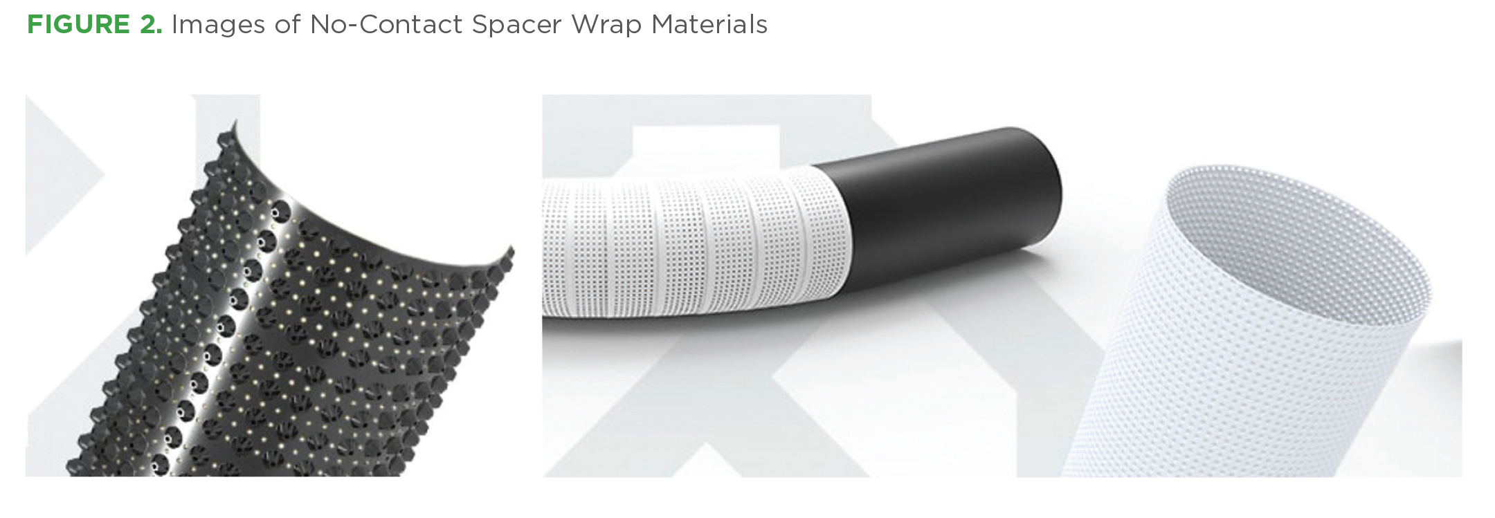
The 2023 revision highlights porous materials that reduce moisture ingress down to the pipe wall and thus mitigate the spread of any moisture along the pipe wall. Additionally, the use of material spacer wraps (e.g., PVC and/or PTFE) between the pipe wall, the insulation material, and cladding, has been demonstrated to offer further improvements to the acoustic, thermal, corrosion, and stress corrosion cracking (SCC) mitigation performance.
The original 2003 standard identified the combination of thermal and acoustic systems, though noted that the thermal requirements of insulation are beyond the scope of the standard. The standard presented that for hot services, the same porous material can be used for thermal and acoustic insulation, though the thickness would be determined by the more stringent requirement. For cold services, the previous version of the standard discussed the use of a rigid thermal insulation (PIR/cellular glass) with an acoustic insulation placed on top of the thermal insulation.
Within the 2023 revision, it is now possible to combine the thermal credit of flexible acoustic materials, such as aerogel blankets and FEF, to reduce or even replace the rigid thermal materials and thus provide a combined thermal-acoustic system. This approach has the potential to significantly reduce the thickness of the system and reduce the cost of installing insulation systems, steelwork, cladding, etc. As with the hot services, the thickness of the system used for cold service is determined by the more stringent requirement. With cold service systems, the use of vapor barriers/seals remains crucial.
The 2003 version of the standard specifically says in Clause 6.3 that the porous layer should be added on top of any rigid thermal layers. The 2023 revision of Clause 6.3 specifically now allows for the inclusion of FEF and aerogel blankets for the porous layers, and also specifically introduces the combination of the thermal–acoustic function that recognizes the thermal functionality of the porous layer.
Additionally, the standard now highlights the approach of using only flexible porous layers (with some layers as sacrificial thermal layers) as the whole thermal-acoustic system. This example seeks to show the possibility of 1) taking the thermal credit of the additional acoustic porous layers on top of a rigid thermal layer, which reduces the amount of rigid insulation required; and 2) using only a flexible porous layer to achieve both thermal and acoustic performance. These different approaches may be beneficial for those seeking to reduce the footprint of the piping systems or the amount for metal cladding required.
Worked Example
Examples of such systems are presented in Figures 3–5 as a worked example for a cold service system.
Assuming the thermal requirement for heat gain less than or equal to 25W/m2, a comparison of typical thermal insulation materials was calculated according to ASTM C680-19.
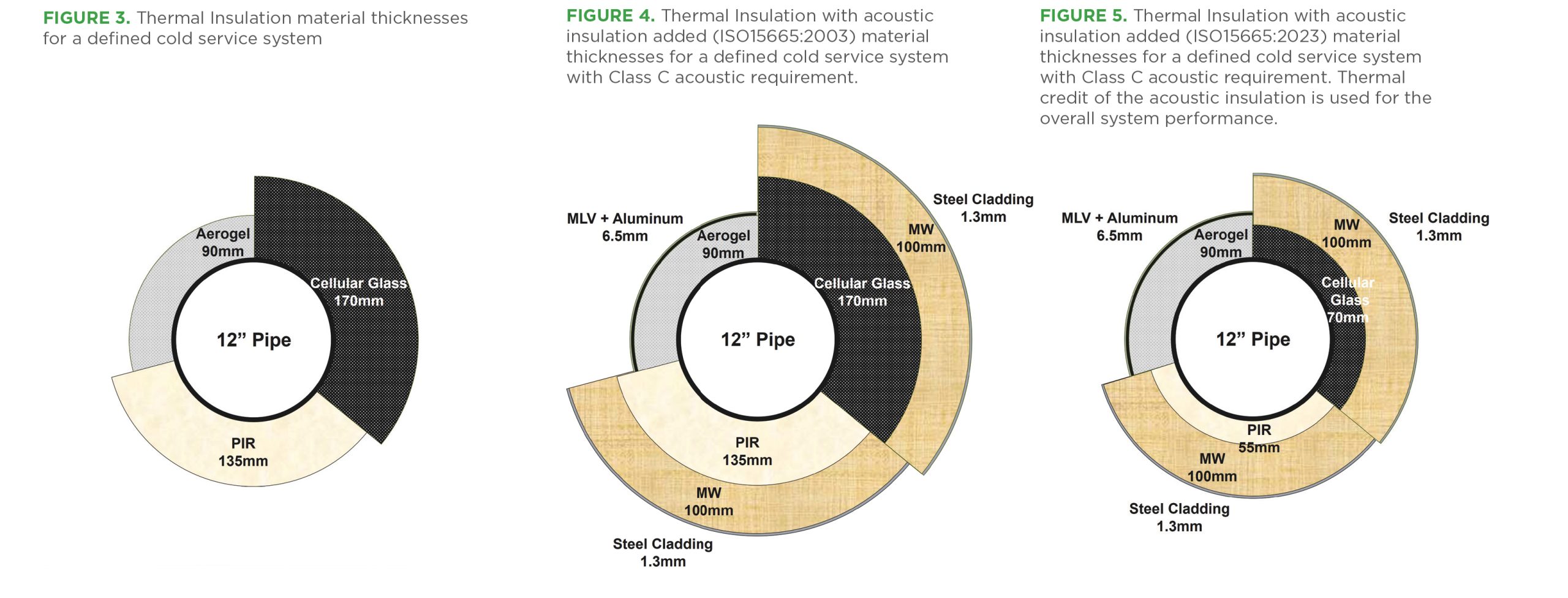
Assuming a 12” pipe on a liquified natural gas process plant operating at -163°C (-261°F) with an ambient temperature of 24°C (75°F), wind speed of 1 m/s; relative humidity of 80%, and an emissivity of 0.3, the following materials were compared: aerogel, cellular glass, PIR, and mineral wool.
The heat gain of the above insulation materials was calculated to be 39.5 W/m for the aerogel, 44.9 W/m for the PIR, and 51.2 W/m for the cellular glass.
Because of the different thermal properties of different materials, varying thicknesses of thermal insulation are needed to provide the required thermal performance. However, if we now consider an additional acoustic requirement for ISO15665 Class C, the 2003 standard would consider the following systems to be suitable as a thermal plus acoustic performance.
The example presented in Figure 4 would meet the thermal requirement and the acoustic requirement. The new standard offers two thermal performance designs with a porous layer and then with or without a rigid layer, depending on the design goals. However, the 12” pipe with 135 mm of PIR applied will have an effective diameter of 594 mm (~24”), and with the 170 mm of cellular glass, this diameter would be 664 mm (~26”).
It should be noted that where rigid thermal insulation is applied to the mid-diameter pipes
(300–650 mm diameter), the acoustic classification may change from a mid-diameter class requirement to a larger class requirement. Care should be taken to apply the correct classification of acoustic system construction. In this instance, for a Class C mineral wool system, there would be no change in construction for the cellular glass to meet Class C3; however, for other material systems, changes may be required.
The 2023 revision of the standard allows the possibility of using an appropriate flexible (porous) material for thermal insulation and acoustic insulation. In this example, as the 90 mm of aerogel blanket required for the thermal insulation purpose is much thicker than the acoustic thickness for the Class C2, it would only be necessary to add the appropriate amount of mass loaded vinyl and cladding to the outside of the aerogel blanket (as certified in independent testing) to complete the thermal-acoustic system.
Adding the mineral wool system on top of the rigid insulation would increase the diameter of the pipe by a further 200 mm. In such circumstances, the PIR + mineral wool system would extend a 12” pipe to 795.3 mm (~31”), and the cellular glass + mineral wool system from 12” to 865.3 mm (~34”). The aerogel thermal-acoustic system would increase the 12” pipe to 516.5 mm (~20”).
However, if the thermal credit of the acoustic systems is considered to provide a true thermal and acoustic combined system, the thicknesses can be further reduced. Using a single type of material for both thermal and acoustic performance, the thickness can be more efficiently minimized. Figure 5 highlights these advantages.
By taking the thermal credit for the mineral wool used in the system, it is possible to reduce the amount of PIR and cellular glass used in the system (note the acoustic system used on top of the rigid material must remain the ISO15665 class certified thickness and construction). Taking this combined approach from ISO15665:2023, these systems have reduced the PIR and mineral wool system from 795.3 mm to 635.3 mm (~31” to ~25”), and the cellular glass and mineral wool from 865.3 mm to 665.3 mm (~34” to ~26”). The aerogel system remains significantly thinner at 516.5 mm (~20”).
Calculating the systems in Figure 5, according to ASTM C680-19, the heat gain (linear) for each system was predicted to be 39.5 W/m for aerogel, 47.5 W/m for PIR and mineral wool combined, and 49.1 W/m for cellular glass and mineral wool combined.
Removable Acoustic Jackets
In 2003, Clause 7.4 made cursory mention of the usefulness of acoustic “blankets.” Due to the advances in material technology, the use of the term “removable blankets/jackets” became more prevalent by 2023. The revision has moved to acknowledge this change, introduce a more detailed description of the usefulness of this measure, and present details relating to the construction requirements.
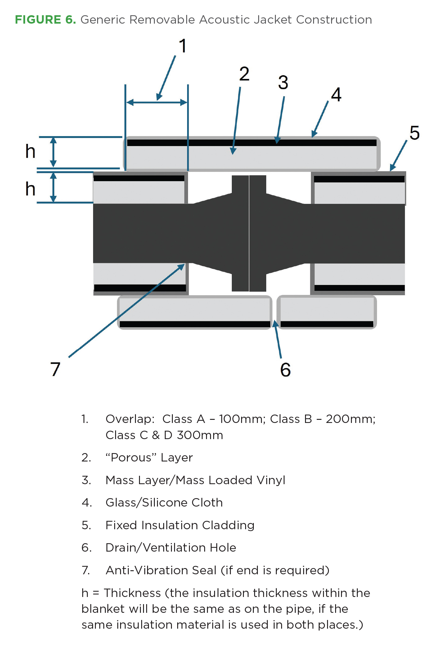
Removable acoustic jackets must be composed of a porous layer and the additional mass layers within a glass/silicone cloth jacket that is designed to fit the shape of the valve/flange/pipe. The jacket construction should have the same insertion loss class as the fixed insulation system used either side of the valve/flange; and, depending on the classification and the construction used, should have an independently tested and certified insertion loss performance. The jacket should overlap the adjacent insulation by 100 mm for Class A, 200 mm for Class B, and 300 mm for Class C and D. A generic construction diagram is presented in the standard in Appendix D, and is shown in Figure 6, below.
Determination of Infield Sound Insertion Loss (Sound Pressure)
Determining the insulation insertion loss was discussed in detail in the 2003 standard, and the laboratory method remains valid and has not been updated. However, it was considered that the infield method required expansion for the sound pressure methodology. Detailed guidance in how to measure and calculate the insulation insertion loss in the field using a sound pressure methodology has therefore been provided in the revision.
Generally, the sound pressure level method for determining insertion loss is the least accurate method. Criteria are presented for checking whether the sound pressure method can be suitable. Where the criteria are not met, the methodology for sound power is recommended. Locations for measurement are presented, and formulas are given for using the results of the measurements to determine the insertion loss.
Summary
Revision of the ISO15665 standard has been 20 years in development. The revision has combined the original document and the addendum produced by Shell DEP 31.46.00.31 to bring all insertion loss classes and performances into one document. Advances in insulation materials technology have improved the insertion loss performance and reduced weight and thickness of insulation. The scope of the standard has now widened to recognize such materials to be used.
By introducing these approved materials, it was also necessary to de-emphasize previous guidance on standard system constructions as they appeared in Clause 9. Though these constructions remain for information purposes in the Appendix, the emphasis of the standard is now on the testing and certification of acoustic insulation systems, regardless of the material used. Materials can now be selected for other requirements (thermal/CUI protection etc.), constructed and tested to meet the insertion loss requirements laid out within the standard.
Additionally, the change of focus from the design of independent thermal and acoustic insulation systems to one where the thermal contribution of the acoustic insulation is considered provides a method for reducing pipe diameters in thermal-acoustic systems.
The other key revision is the more detailed introduction of removable acoustic jackets/ blankets to be used where fixed insulation may not be suitable. Rather than relying solely on enclosures of boxes to envelop items such as valves or flanges, advice is provided for the construction and application of flexible acoustic jackets. Such jackets can be installed and removed easily, allowing for maintenance and inspection of these items while providing equivalent sound attenuation as that of the fixed insulation system adjacent to these items.