A Different Perspective: Insulating Piping System at a Power Plant
A steam-generating boiler has many different piping systems that require insulation. Insulating pipes is a common occurrence, whether done at the initial piping install, as repair or replacement, or even at the pipe welds during inspection. How these piping systems are insulated will depend upon temperature, location, and the specifications or applications approved at any given plant; but most importantly, you need to understand piping location. Understanding this basic directional compass will allow you to navigate around a boiler; communicate with other crafts; and locate the specific piping system requiring insulation (i.e., floor elevation).
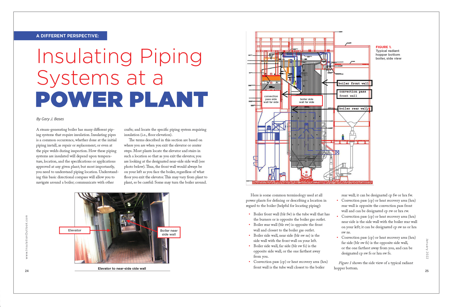
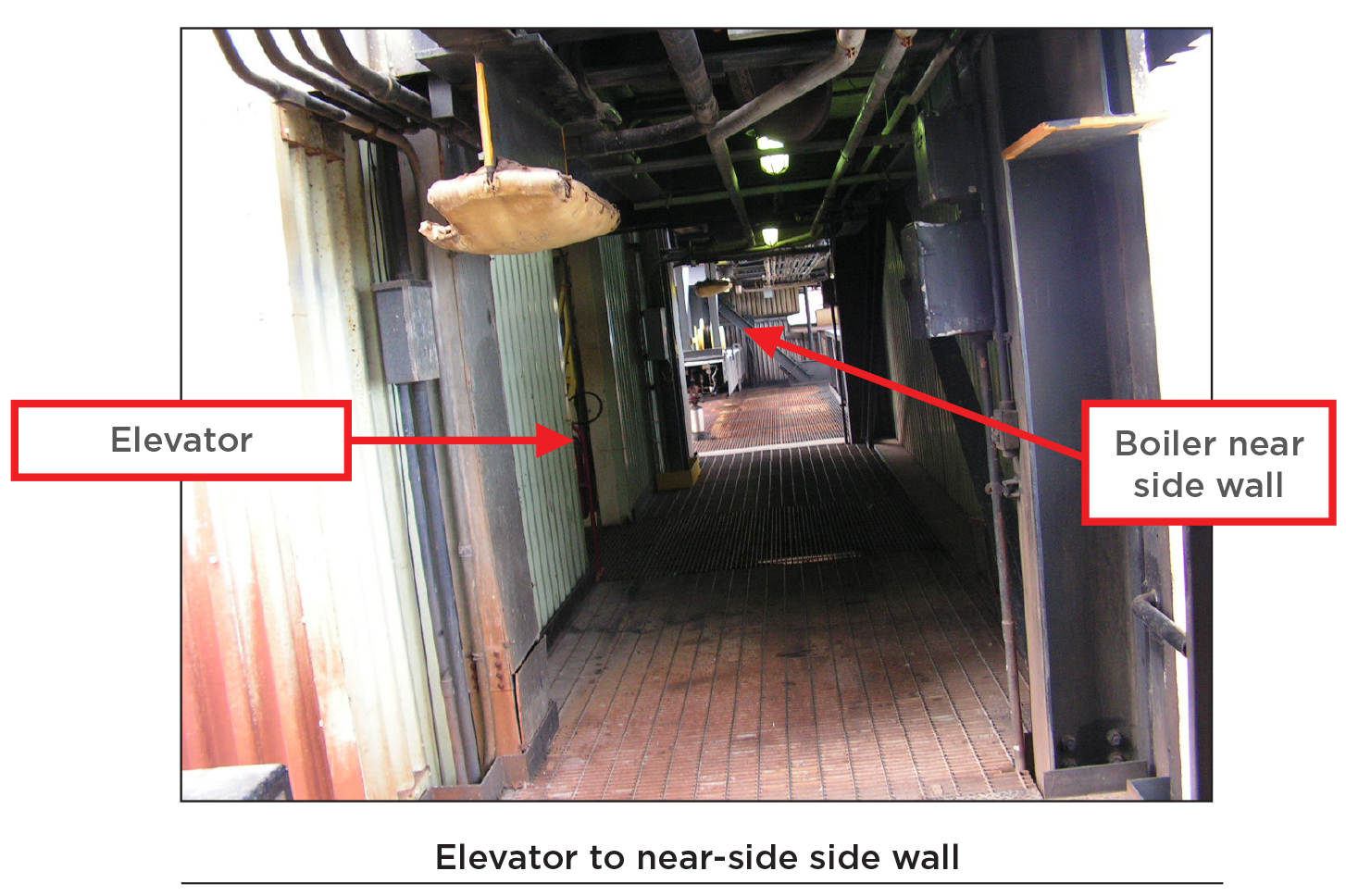
The terms described in this section are based on where you are when you exit the elevator or center steps. Most plants locate the elevator and stairs in such a location so that as you exit the elevator, you are looking at the designated near-side side wall (see photo below). Thus, the front wall would always be on your left as you face the boiler, regardless of what floor you exit the elevator. This may vary from plant to plant, so be careful: Some may turn the boiler around.
Here is some common terminology used at all power plants for defining or describing a location in regard to the boiler (helpful for locating piping):
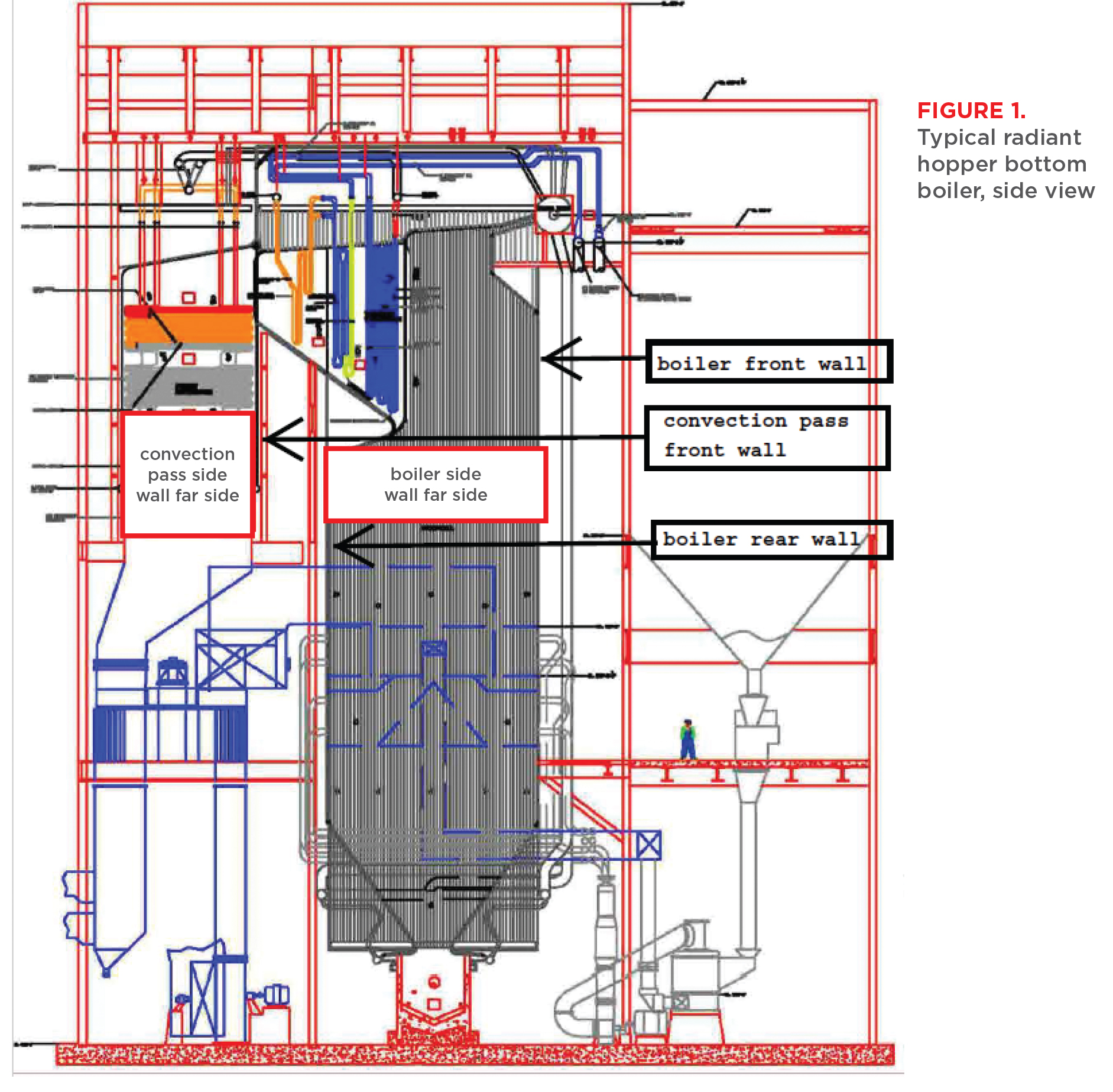
- Boiler front wall (blr fw) is the tube wall that has the burners or is opposite the boiler gas outlet.
- Boiler rear wall (blr rw) is opposite the front wall and closest to the boiler gas outlet.
- Boiler side wall, near side (blr sw ns) is the side wall with the front wall on your left.
- Boiler side wall, far side (blr sw fs) is the opposite side wall, or the one farthest away
from you. - Convection pass (cp) or heat recovery area (hra) front wall is the tube wall closest to the boiler rear wall; it can be designated cp fw or hra fw.
- Convection pass (cp) or heat recovery area (hra) rear wall is opposite the convection pass front wall and can be designated cp rw or hra rw.
- Convection pass (cp) or heat recovery area (hra) near side is the side wall with the boiler rear wall on your left; it can be designated cp sw ns or hra sw ns.
- Convection pass (cp) or heat recovery area (hra) far side (blr sw fs) is the opposite side wall, or the one farthest away from you, and can be designated cp sw fs or hra sw fs.
Figure 1 shows the side view of a typical radiant hopper bottom.
Throughout the industry, there is a lot of individually insulated piping of various sizes. A typical 600‑megawatt radiant boiler could have more than 3,500 linear feet of individually insulated piping and over 2,800 square feet of mineral wool blanket for piping that can be bundled. A few examples of such piping systems are described below.
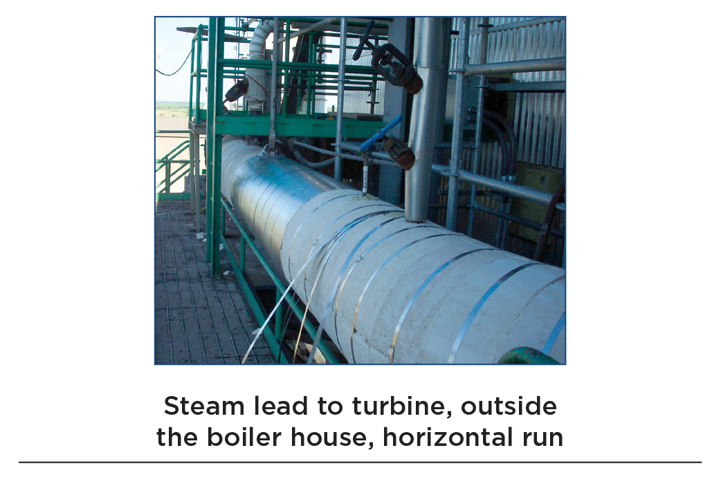
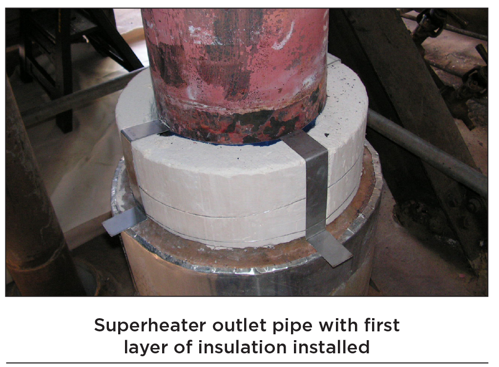
Steam leads (primary and secondary outlets) from boiler to turbine. Steam leads are pipes that carry superheated dry steam from the boiler to the electric generator or turbine. The temperature of the dry, superheated steam can be as high as 1,030°F at the secondary superheater outlet pipe and 953°F at the primary superheater outlet.
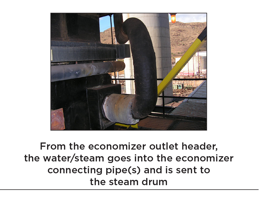
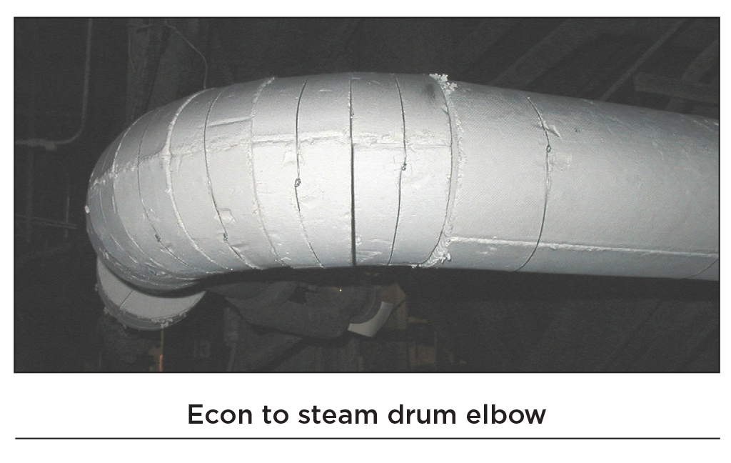
Economizer outlet piping that feeds the boiler with preheated water. For a radiant boiler, water circulates up through economizer tubes to the economizer outlet header, where it reaches 644°F. From the economizer outlet header, the water/steam goes into the economizer connecting pipe(s) and is sent to the steam drum.
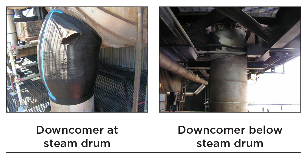
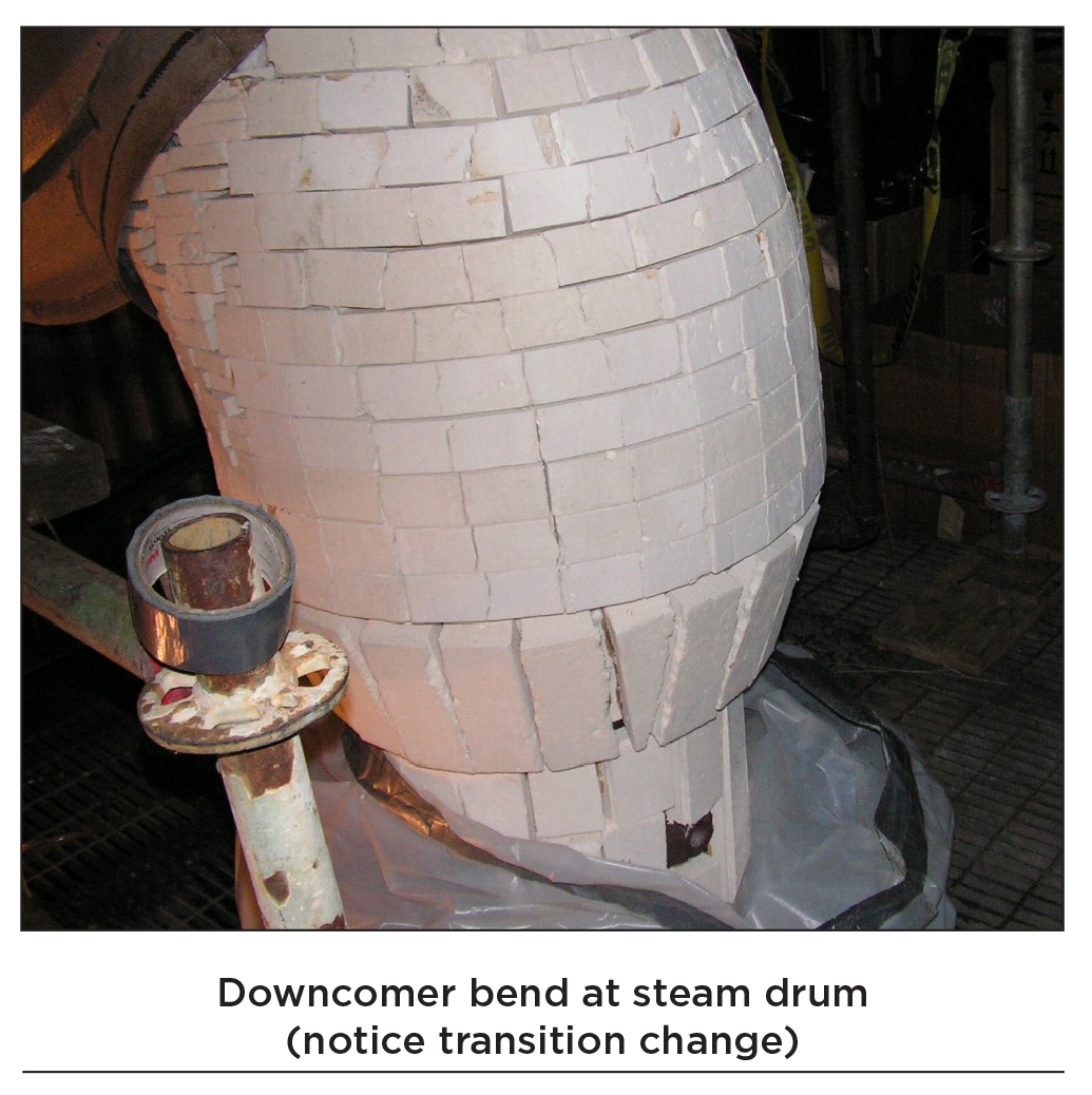
Downcomers from steam drum to lower side wall headers. Water/steam enters the steam drum from the economizer outlet header via the economizer connecting pipe and is forced down pipes called downcomers by gravity to feed the lower water wall headers of the convection pass and furnace walls.
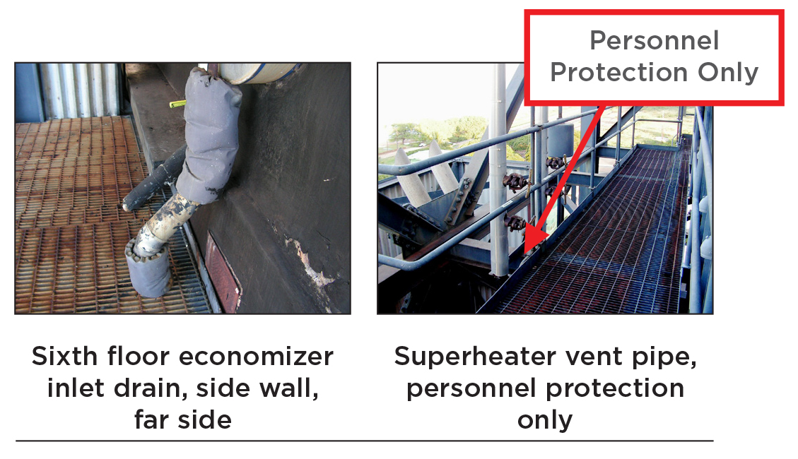
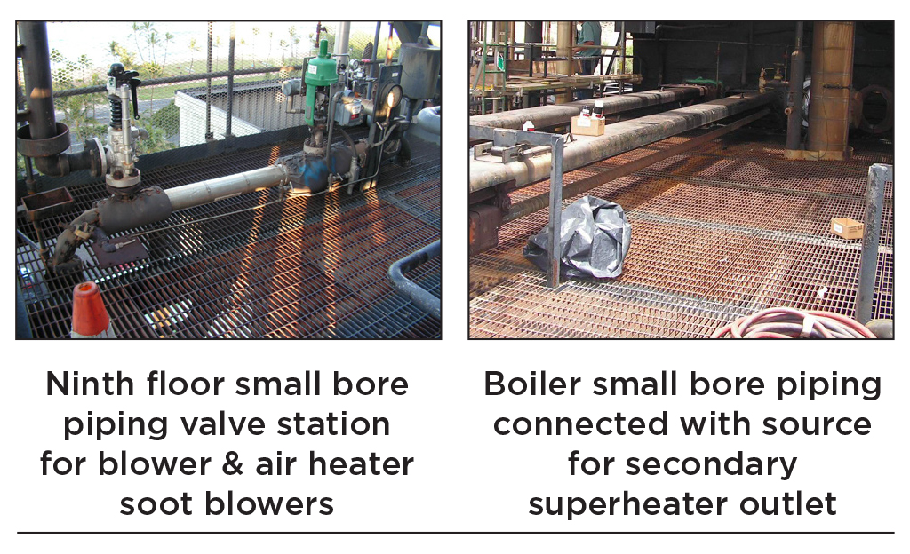
Small bore piping (drain, vent, and soot blower) is piping usually less than 4″ iron pipe size (IPS) with temperature based on source of steam or water. Drain lines from the economizer inlet can be 350°F, compared to drain lines coming from the lower water wall headers at 626°F.
Soot blower lines can come from the primary superheater header (953°F) or secondary superheater header (1,030°F).
As is evident from the photos, each system presents its own unique situations. Here is a quick summary of the particular issues for each system:
Steam leads and downcomers
- Size of the pipe can be 24” to 36” outside diameter (OD) or greater
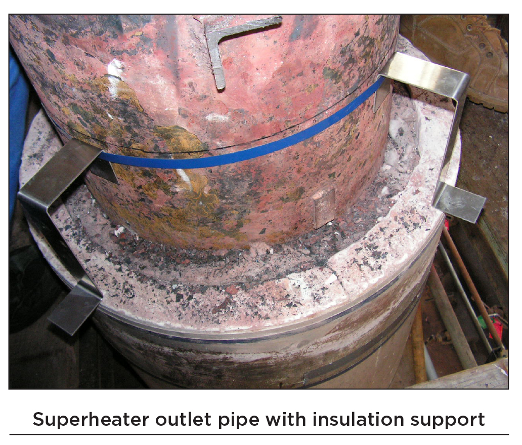
- Require insulation supports on vertical runs with drops greater than 12 feet long
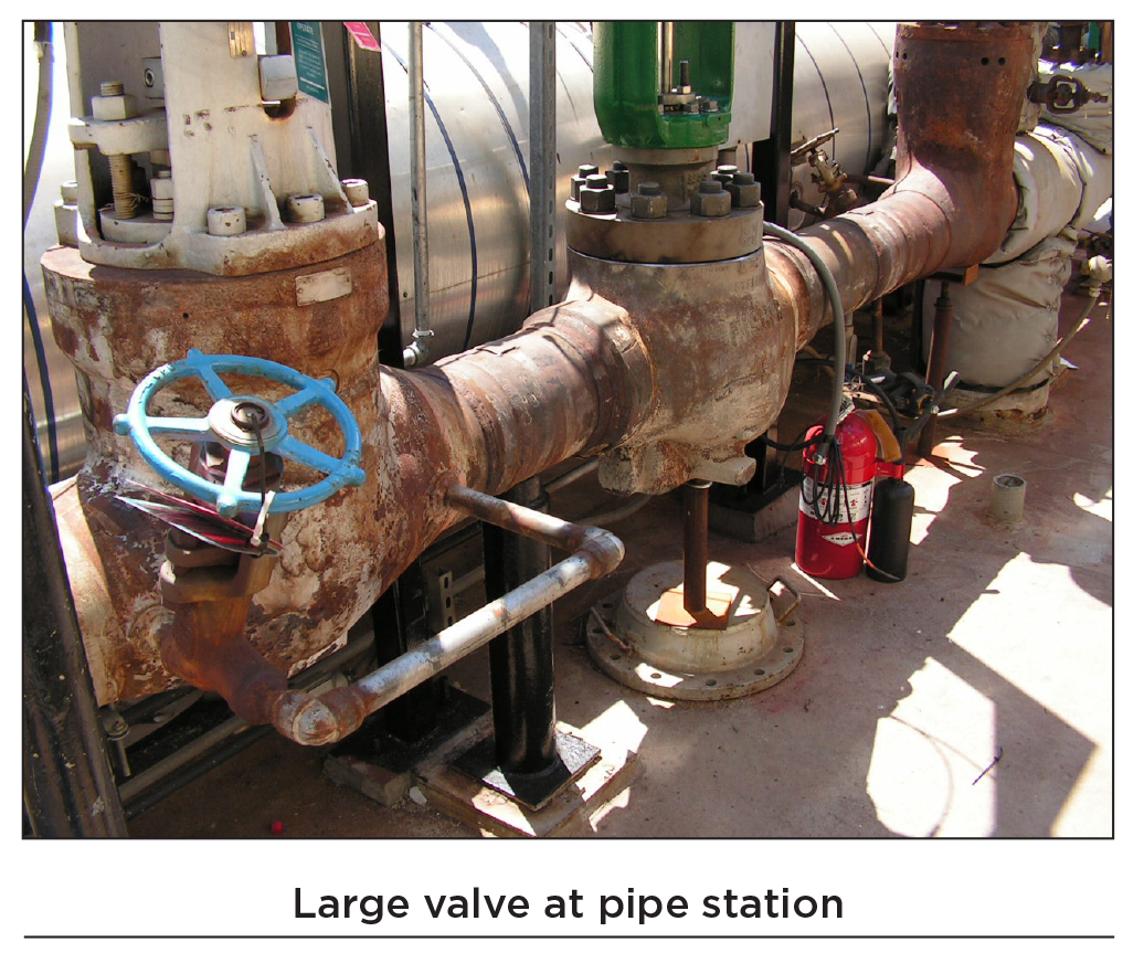
- Has large steam valves that require insulating
- Large and long radial bends require a lot of miters and cuts
- Can be difficult to access due to plant configuration
Economizer outlet pipe
- Size of the pipe can vary from 8” to 24” OD or greater. Any pipe 12” OD and greater must have supports on vertical runs with drops greater than 10 to 12 feet
Small bore piping
- Size of the pipe can vary from less than 1” OD to 4” OD at any given area, which may change the insulation thickness requirement
- Tight configuration of piping may require bundling of piping
- Piping source may change at any given area, which will require special attention so as to get the correct insulation thickness
- Vent piping may only require personnel protection at platforms and grating areas
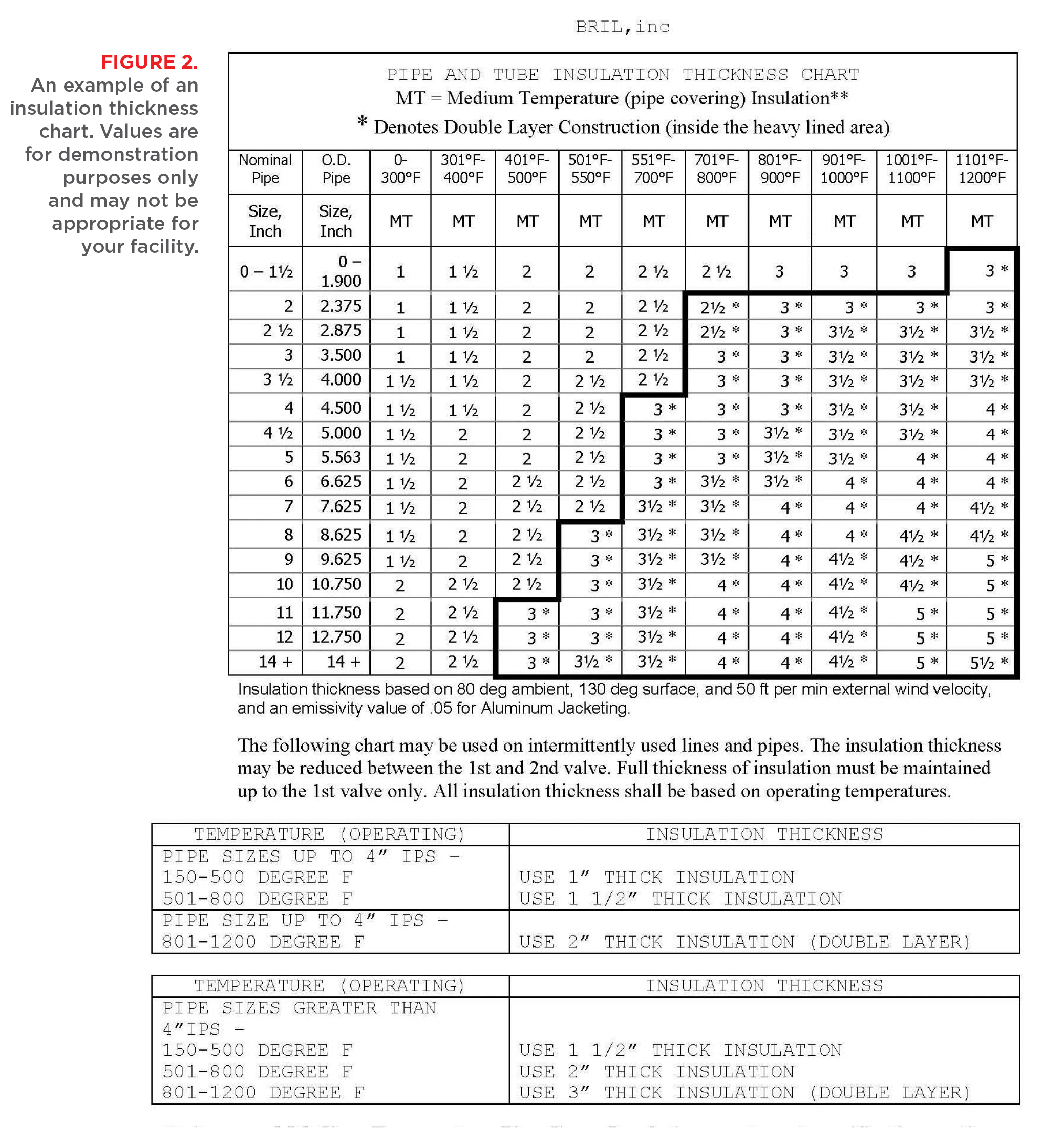
To detail the individual steps for insulating and jacketing all of these piping systems would make this a very long article. Instead, we will list the major steps and methods for installing pipe insulation correctly. The power plant or design engineer should provide an insulation thickness chart for establishing the correct insulation thickness and the operating temperatures. Figure 2, on page 28, shows an example of insulation thickness chart.
In addition to the insulation thickness requirement, the power plant or design engineer also may specify the application and material types to be used. While not the only options, the following are materials that the author has used for insulating and jacketing piping at a power plant:
- Calcium silicate pipe insulation meeting ASTM C533
- Mineral fiber pipe insulation meeting ASTM C547
- Lacing wire #14ga soft annealed lacing wire stainless steel or mild steel, based on temperature
- Pipe jacketing .016” aluminum with a poly-type moisture barrier or equal
- Screws #8 x 1/2″ long self-tapping type-A point AISI-410 minimum
- Bands ½” wide x .020” thick stainless steel or galvanized, based on temperature
The following are examples of good industry standard practices.
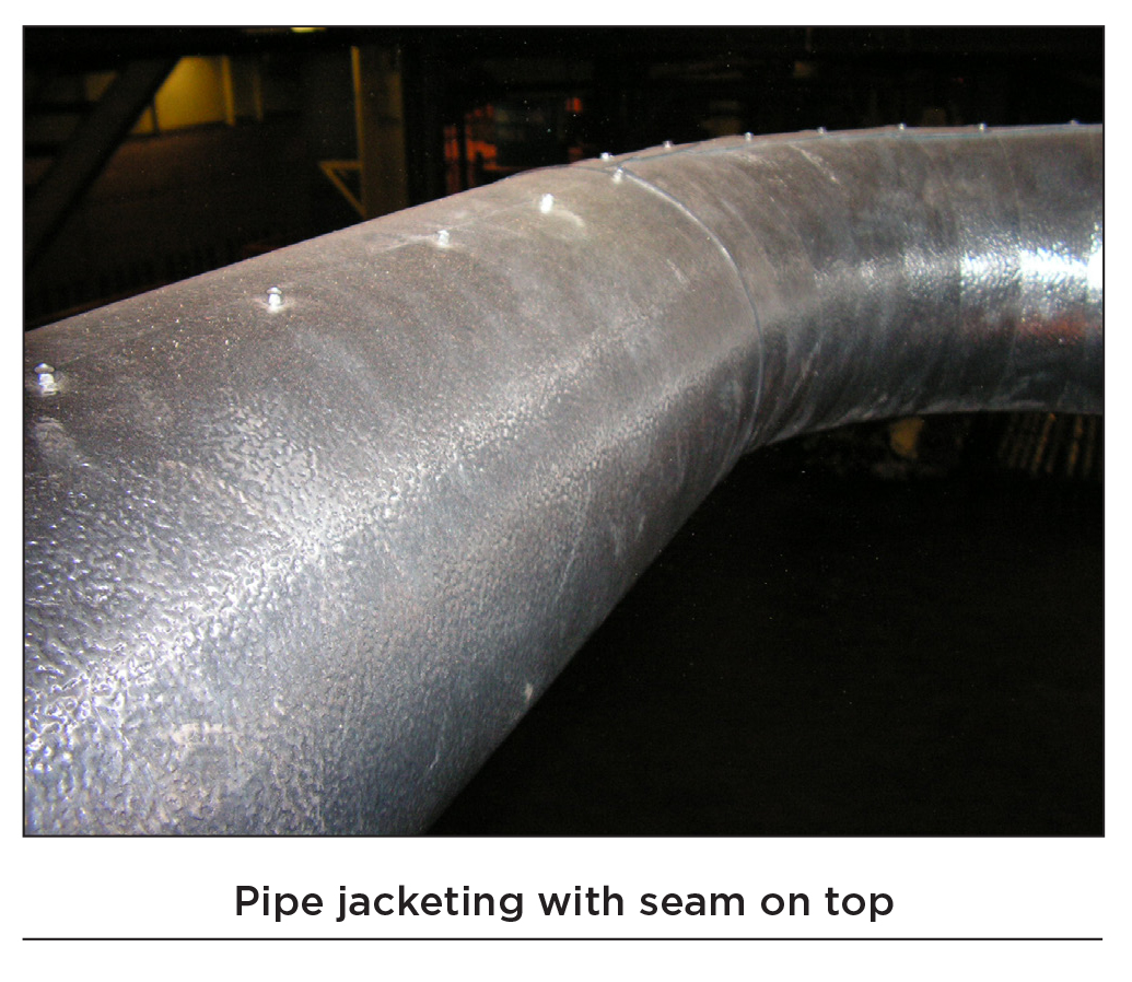
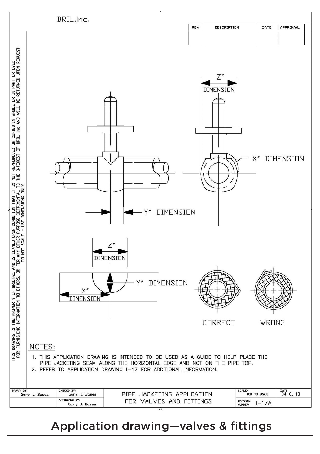
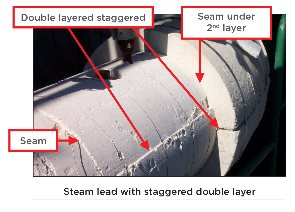
Wherever possible, jacketing seams should be located on the opposite of the most viewed side of the pipe. Jacketing seams should not be seen from a walking platform or grate, and placed along the horizontal edge and not on the pipe top. The seam should have a safety hem and kick out on edge for strength and watertight seal.
Pipe insulation for single-layer application does not have to be staggered.
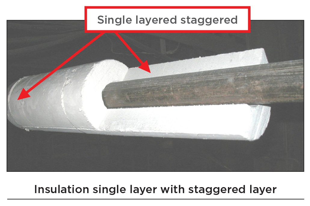
Pipe insulation for double-layer application must have the second layer staggered so the seams or joint do not align with the first layer.
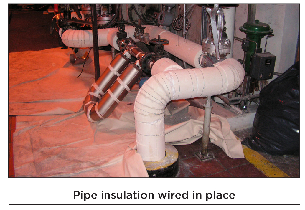
Pipe insulation should be wired in place and never glued in lieu of using wire.
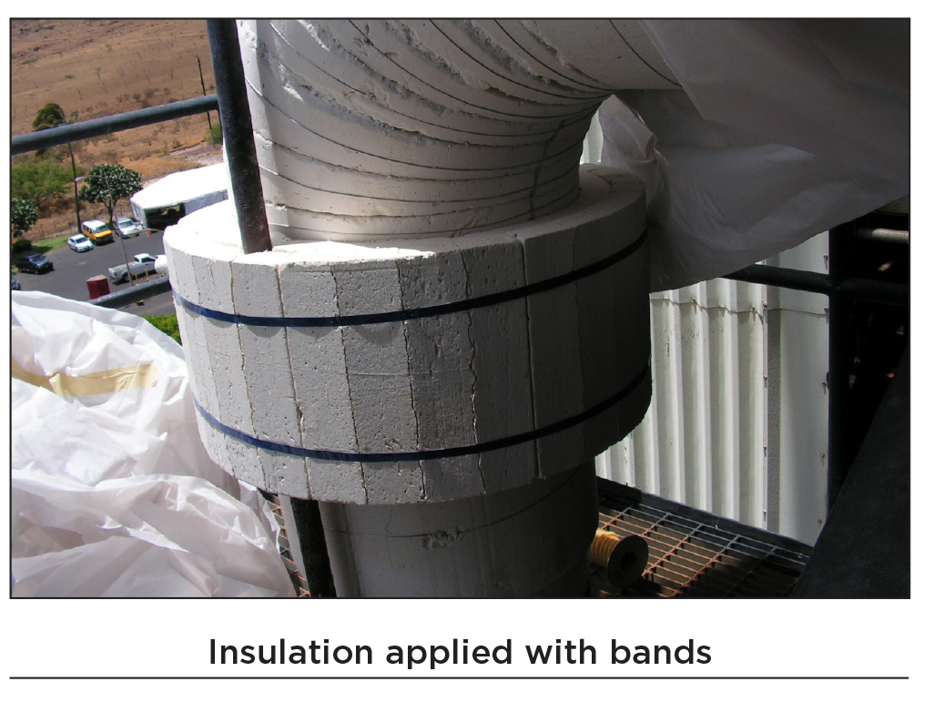
Banding of piping is an acceptable alternative to using lacing wire for holding the insulation but not as a jacking attachment in lieu of screws.
Vertical drops for piping greater than 12” OD must have an insulation support every 10 to 12 feet.
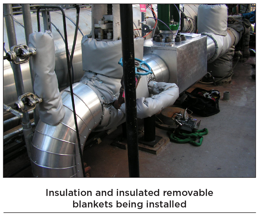
Elbows and bends present their own unique issues and require the most experienced insulator due to all the cutting and fitting. Pipe insulation should be butted tightly together, even on bends and elbows. Any open joints, cracks, holes, or voids greater than 1/16” must be filled in to the depth of the insulation with insulating cement made from the same or equal material as the surrounding insulation. This applies to single- or double-layer application. The reason it is not recommended to pack the void with loose insulation is because packing may not get all the way down to the pipe. In addition, the density of the packing may be less than the surrounding insulation, creating a potential hot spot. That is why the cuts and miters require the most experienced insulator in order to get the joints insulated as tight as possible. The more you fill in the joints with material, the more likely it is that you may lose heat (see photos).
Piping will eventually be connected to a valve, and some can be quite large and challenging.
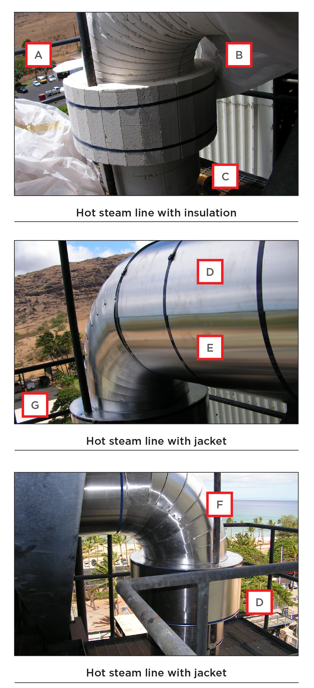
When properly insulated and jacketed, plant piping should be thermally efficient and aesthetically pleasing to the eye. It takes an understanding of what is acceptable and what is not to get the utmost value for the dollar. The pictures below show a hot steam line that has been completed. Can you see what is not in compliance?
Answers: (A) Insulation cuts on bend are not tightly fitted, and there are large gaps between cuts. (B) Insulation in joints is used instead of insulating cement. (C) Bottom below banded area has insufficient lacing wire. (D) Bands are used in lieu of screws on horizontal section of jacketing. (E) There is no kick out at horizontal jacketing seam. (F) Jacket seam is on the wrong side of pipe, visible from platform. (G) There is no caulking or flashing at support rods penetrating jacketing.
Conclusion
With so much plant and boiler piping requiring insulation and jacketing, it is imperative that power plants get well insulated and jacketed piping systems to keep the boiler and plant energy efficient. Paying attention to basic insulating and jacketing practices will help ensure that happens.
References
The information contained in this article has been primarily obtained from public sources, without input from any of the boiler manufacture companies directly.
- Combustion Fossil Power – Combustion Engineering, Inc. 4th Edition (1991)
- Steam, its generation and use – Babcock & Wilcox Company, 40th Edition (1992)