A Model Approach to Improving the Accuracy of Insertion Loss Predictions
Identify and fix any acoustical issues in your system

The machinery and high-velocity processes that power industrial facilities create inherently noisy environments. Sustained exposure to loud noise is a risk faced by about 22 million employees in the United States, according to the National Institute for Occupational Safety and Health (NIOSH).1 Globally, it is estimated that 120 million people have “disabling hearing difficulties,” according to the World Health Organization (WHO).2 While noise-related damage can occur via sudden and direct exposure, or more sedulously, both types of exposure have been linked to adverse effects such as difficulty hearing and trouble with verbal communication, interaction, and behavior, according to WHO reports. The good news is that these problems can be mitigated; and multiple strategies can be employed to reduce loud industrial noise, including the use of specifically designed insulation systems.2 A series of laboratory tests conducted at renowned acoustic facilities in Europe was used to help create and validate a theoretical model to predict acoustical performance of insulating systems intended for use in industrial noise control. Expanding upon traditional statistical models, the new theoretical model provides a much higher level of accuracy to assess how various combinations of insulating material and jacketing may reduce noise in the industrial environment.
Reducing the Racket
Any effort to reduce noise should consider the noise source and its proximity to interventions. Generally, the closer the intervention is located to the source of the noise, the better the noise abatement will be. Several steps can be taken to reduce noise levels and the damage noise poses during working hours. The NIOSH Buy Quiet program was established to support the purchase, use, and creation of quieter alternatives for industrial equipment and facilities. Other interventions include implementing engineering controls to provide barriers to noise or muffle the amount produced; using administrative controls, such as limiting time spent in a high-noise environment; and providing personal protective equipment (PPE) like ear plugs.1 One commonly used approach is to build a structure around the noise-emitting device to block sound transmission.
Of course, it is not always practical or cost-effective to replace equipment. As networks of piping play a central role in driving industrial processes, installing pipe insulation with appropriate jacketing presents an attractive intervention to stop noise close to the source. Insulation can help provide sound dampening by lowering the amount of noise transmission or reducing how much is radiated into a given space. The ISO standard 15665—Acoustic insulation for pipes, valves, and flanges—establishes a testing process to measure the acoustic performance of pipe insulation systems.3
The process to design pipe insulation systems that help limit noise transmission and radiation is complex and costly. There are only a few laboratories in the world equipped with the systems to thoroughly assess acoustical interventions. As such, system designers may turn to statistical modeling to help predict the insertion loss of a given intervention. Insertion loss refers to how effective an intervention is at reducing noise. This metric describes the difference in the sound level generated when a non-insulated pipe is tested compared to what is created when an insulated pipe is exposed to the same conditions in a testing facility. Following a series of 32 laboratory tests and the use of a statistical model, researchers have created a new theoretical model that provides a more accurate prediction of insulation performance, especially when applied to larger pipes.
Evaluating Insulation Performance
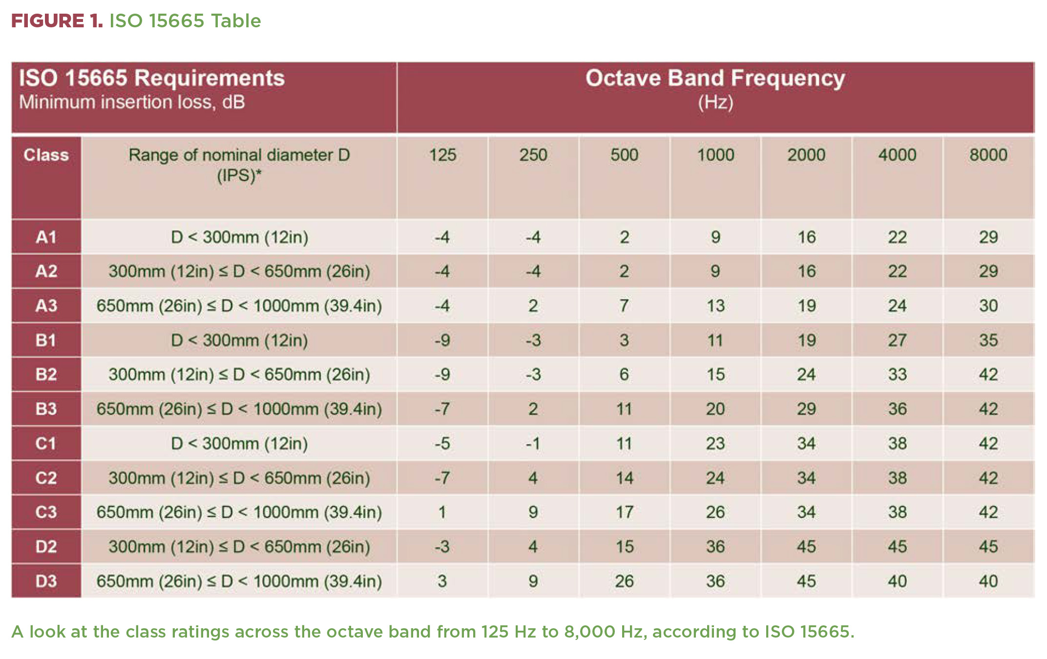
The ISO 15665 standard used to evaluate acoustic performance of pipe insulation classifies insertion loss for multiple frequencies. The standard also establishes a physical testing process and rating system for the insulation applied. The classes in the standard are A, B, and C, with each letter relating to the insertion loss performance. A fourth category, D, was developed outside of the standard and has been accepted by the industry to describe the highest level of acoustic performance from pipe insulation. The ISO standard also applies to pipes in a series of diameters—less than 300mm, 300mm to 650mm, and 650mm to 1,000mm—which are labeled 1, 2, or 3, respectively, within the associated class (see Figure 1).
The test setup used to examine the function of acoustic insulation designs is also delineated in the standard. During the physical testing process, a pipe of the necessary diameter is installed in a reverberation room (see Figure 2). When in place, the pipe crosses the room, and both ends of the pipe exit through side walls. A speaker is used to generate acoustic excitation on the inside of the pipe, and sound power levels are measured inside the main space. Initially, the pipe is tested with no insulation covering. Once the baseline readings have been established, the intended insulation covering is added and secondary testing is completed. The insertion loss from the applied acoustic insulation is then determined using the difference between the two measurements adjusted for the change in sound absorption from the insulation system.

A series of 32 tests were conducted at Gryfit Laboratory of Acoustics in Poland examining different kinds of both high- and low-temperature insulation designs intended for use on medium size or number 2 pipes (300mm to 650mm). The testing examined combinations of mineral wool and cellular glass pipe insulation, along with loaded vinyl and jacketing. The intention was to find the insertion loss of the different designs.
As testing is extremely costly, and limited resources are available for conducting tests, researchers sought to create a model capable of efficiently providing estimations of the insertion loss and class rating for a proposed insulation design.
Developing Statistical, Theoretical Models
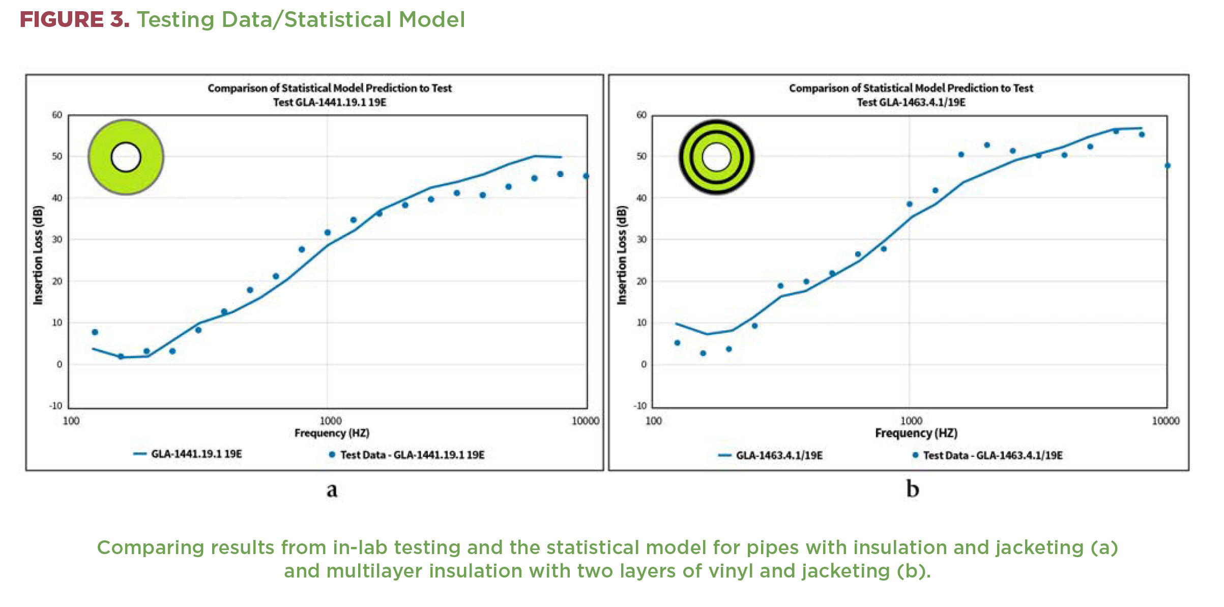
The testing series provided data related to insulation designs and an opportunity to establish predictive models that could be used to provide an estimation for future designs. Initially, the test data generated an informed statistical model. The model created provided an acceptable estimate for the insertion loss on a range of 100 Hz to 10,000 Hz, demonstrating an R-sq(adj) value of 0.947 (see Figure 3).
An “aha” insight was that the industry standard model was only able to provide the correct class rating 66% of the time. In light of this observation, work started on a theoretical model to help increase the accuracy of insertion loss predictions.
A one-dimensional model was chosen to map the movement of energy from the interior to the exterior of the pipe. The one-dimensional model was created using proprietary modeling software and is based on Delany-Bazley research for fibrous, sound-absorbing materials. The model was modified to estimate both absorption and transmission loss with layered porous materials, and to establish normal and diffuse acoustic behavior.4
The objective was to replicate the ISO 15665 measure by predicting the difference between the bare and insulated pipe in terms of transmission loss. This difference corresponds to the change in the energy released into the reverberation testing room.
Initially, the theoretical model did not meet performance expectations, and it had to be revised using statistical regression. The change altered the model’s view of the pipe from being an infinite plane into a finite surface and helped account for insertion loss values beyond 60 decibels. Examining the revised theoretical model determined that it was competent to estimate jacketed pipe insulation performance and insertion loss between 100 Hz and 10,000 Hz. The model had an R‑sq(adj) value of 0.977, which was better than the result generated by the initial statistical model.
Improving Accuracy from 66% to 90%
Additionally, when the theoretical model was used to predict insulation class for the tested insulation systems, it was found to be 90% accurate based on ISO 15665 criteria. In the instances when the theoretical model did not provide the same rating class determined during in-lab testing, the model’s prediction was always conservative, or it generated a lower rating than was found during the in-lab testing. These findings suggest a level of confidence that installing a specific intervention should not lead to underperforming insulation or the need for retrofits. The change in rating estimates also showed an improvement from the statistical model. Additional analysis also highlighted variables that were important in changing the amount of insertion loss generated. Interplay between these elements accounted for most of the alterations to insertion loss.
Based on the results found from theoretical model predictions for the tested insulation systems, additional trial tests were done using the prescriptive pipe insulations in the ISO 15665 standard. In these trials, the theoretical model accurately predicted the results described by the standard. Interest in expanding the testing range to focus on pipes of the largest diameter—650mm to 1,000mm—however, found that the market lacked published results from tested insulation systems for large-diameter pipes. The only published designs found were the prescriptive designs used in the ISO 15665 standard.
The Large-Pipe Challenge
The lack of published data on large-pipe insulation systems indicated the need for additional laboratory testing. Following the decision to conduct additional laboratory testing for large-diameter pipes, it was discovered that only two sites were both interested in conducting the tests and able to do so. Upon further evaluation, it was determined that of the two, only one could conduct testing for the largest diameter pipe. This facility was the Peutz Laboratory for Acoustics in the Netherlands.
A selection of six jacketed insulation systems covering both high- and low-temperature conditions were specified for testing. The insulation systems included cellular glass insulation, aluminum-butyl wrap, mineral wool insulation, bitumen, and stainless-steel jacketing. The insulation systems’ designer also provided a prediction of class rating based on experience.
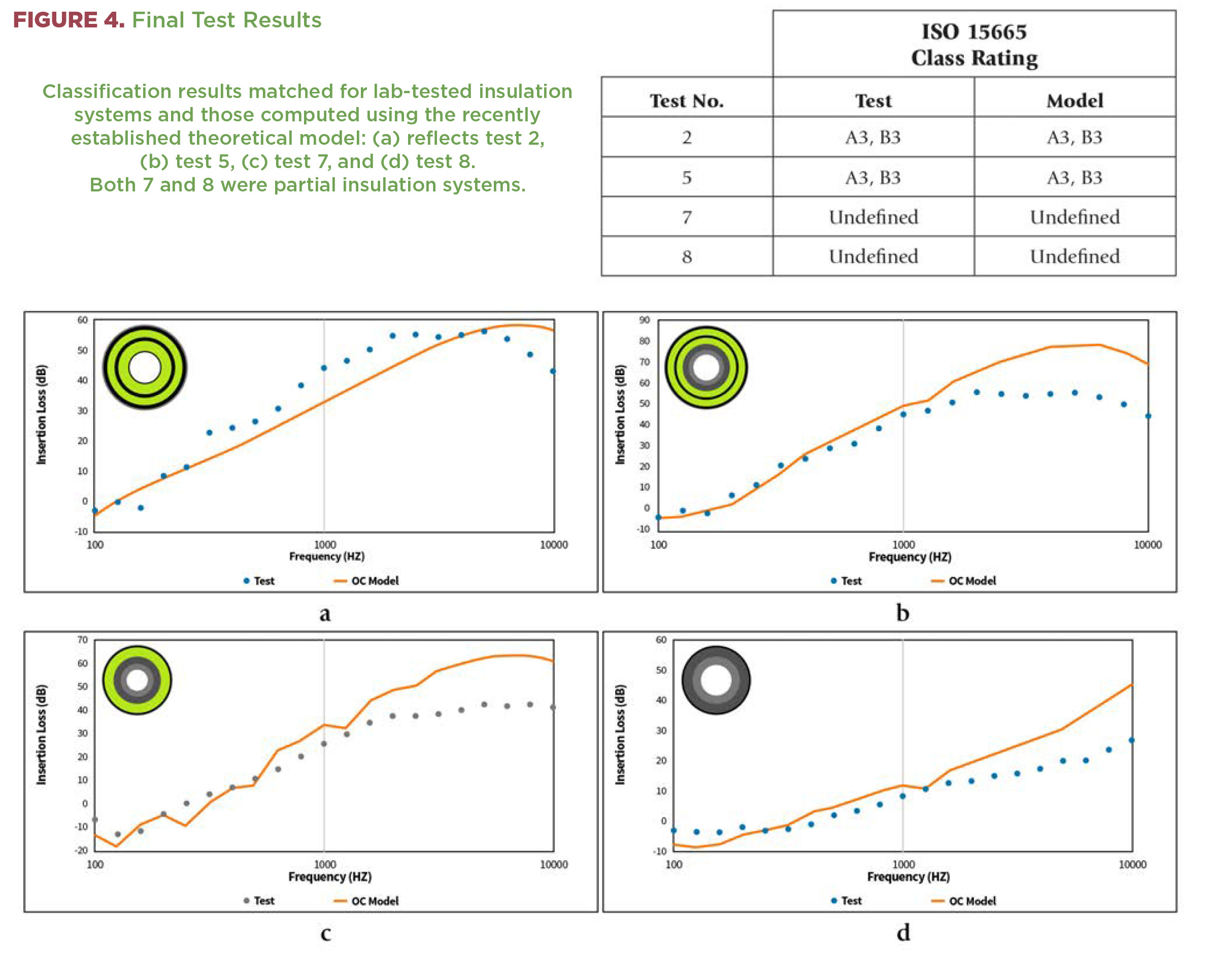
While testing was planned for 2020, the Covid-19 pandemic disrupted the laboratory plan. Two partial insulation systems—two layers of insulation with a mass layer, and no jacket along with a single layer of insulation—were evaluated. Given the time, cost, and challenges involved in the testing process, it became clear why so little information on
large-pipe insulation systems is available in the marketplace.
The results for class ratings determined during testing and those predicted using the theoretical model were the same (see Figure 4). Overall, the theoretical model performed well when used up to 1,000 Hz. When examining large pipes above that threshold, restrictions in test setup (which the model does not share) generated higher insertion loss values for the model than were demonstrated by the physical test. Additionally, both the laboratory testing and theoretical model classified the insulation systems more conservatively than the experienced designer.
Conclusion
Testing new pipe insulation system designs to assess insertion loss is a lengthy and expensive process, particularly so for large-diameter pipe applications. Previously, this combination of challenges may have restricted the number of noise-reducing design options used in industry. The evaluation of insulation systems including insulation and jacketing for medium and large pipes has informed and helped validate a new theoretical model, which can be used to assess insulation systems including those for the largest pipes. The model allows engineers to predict insertion loss and system class designation for new designs, providing industry the ability to examine alternative plans and potentially expand the range of designs in use. The new approach also can help curb the need for laboratory testing until a final design is established.
Growing the range of available insulating systems grants designers, operators, owners, and installers new ways to reduce noise levels and mitigate the consequences noise presents in industrial spaces. Additionally, the data and understanding needed to develop and refine the new model have expanded the comprehension of how different layers interact in insulation systems. These developments provide new insights and may lead to innovative plans and ways to improve acoustic solutions in industrial spaces.
Findings from the research were presented at the virtual 50th International Congress and Exposition on Noise Control Engineering in August 2021.
References
1. National Institute for Occupational Safety and Health, Controls for Noise Exposure, February 2018. www.cdc.gov/niosh/topics/noisecontrol.
2. Berglund, Birgitta, Lindvall, Thomas, Schwela, and Dietrich H. (Eds.), Guidelines for Community Noise. World Health Organization expert task force meeting. 1999.
3. International Organization for Standardization, Acoustics – Acoustic insulation for pipes, valves and flanges (ISO Standard No. 15665:2003), 2003. www.iso.org/standard/28629.html
4. Delany, M. E. and Bazley, E. N. (1970). Acoustical properties of fibrous absorbent materials. Applied Acoustics, 3, 105-116. doi.org/10.1016/0003-682X(70)90031-9