A Study of Industrial Refrigeration Insulation

Summary
Most industrial refrigeration systems use ammonia as the refrigerant and can vary in operating temperature from about -80°F up to 130°F. Many are used in food processing and/or food storage and are located on pipes and vessels in numerous facilities across North America. Due to the relatively cold temperatures, they are subjected to not only severe temperature differences, from the ambient to the cold surfaces, but also severe water vapor pressure differences. Hence, when high-performance water vapor retarders are either not used or, if used, are not maintained, significant ice accumulation can result within the insulation materials, compromising the thermal performance of the insulation materials.
In this study, the author visited more than 20 food processing and food storage facilities, usually when old insulation systems were being removed and replaced, or—in new construction—new insulation systems were being installed. The study focused on selection of insulation materials, installation techniques, maintenance of insulation systems, and long-term performance of those insulation systems. The author concluded the study by making recommendations for installation and maintenance of those insulation systems.
This study was sponsored by the International Institute of Ammonia Refrigeration (IIAR) and the Ammonia Refrigeration Foundation (ARF) and was presented at the 2021 ASTM C16 Symposium.
Introduction
As someone who has worked in the mechanical insulation industry more than 40 years, for both insulation contractors and manufacturers—and dealing with above- and below-ambient applications in industry, commercial buildings, and ships—I thought I had pretty much seen it all. Therefore, when I undertook this study of industrial refrigeration insulation systems for the IIAR and the ARF, I was surprised how the technology was mostly new to me, even though ammonia refrigeration has been used in industry for well over a century. The predominant insulation materials used today (extruded polystyrene, or XPS, and polyisocyanurate, or PIR) also have been used for many years, although the ASTM C1136, Types VII and IX sheet or film vapor retarders, including matching tape, are relatively new, introduced in the past 20 years or so (these are either polyvinylidene [PVdC]) film or poly-aluminum-poly [PAP] sheet). Additionally, what I call “corrosion-inhibiting gels,” which are first applied to the bare carbon steel pipe and equipment surfaces prior to the insulation, are also relatively new. In conducting the study, I found that insulating industrial refrigeration systems is an industry within an industry. Most of the contractors I encountered specialize in this technology and have workers who are specialists in removing and installing refrigeration insulation systems. That is not to say that other insulation contractors cannot do this work; rather, that I found insulation contractors who specialize in refrigeration insulation working on these projects. The old insulation systems being removed and replaced had been designed and installed about a quarter of a century earlier. While most used XPS or PIR insulation materials, many either had no sheet or film vapor retarder at all or had vapor retarders designed for HVAC systems in conditioned spaces, such as conventional all-service jacketing (ASJ) with water-absorbent Kraft paper on the other surfaces. Many also appeared to have been installed with no adhesive applied between outer-layer insulation pieces. None appeared to have been installed on top of corrosion-inhibiting gels, so in many cases the carbon steel surfaces were severely corroded. In fact, the steel pipes were so corroded that, in some instances, the refrigeration contractor simply cut out the old pipes with the insulation system and then installed new pipes prior to having an insulation contractor install a new insulation system. In my observations, the pipes that had been subjected to defrost cycles (i.e., cold, then hot, then cold) were the ones most severely corroded.
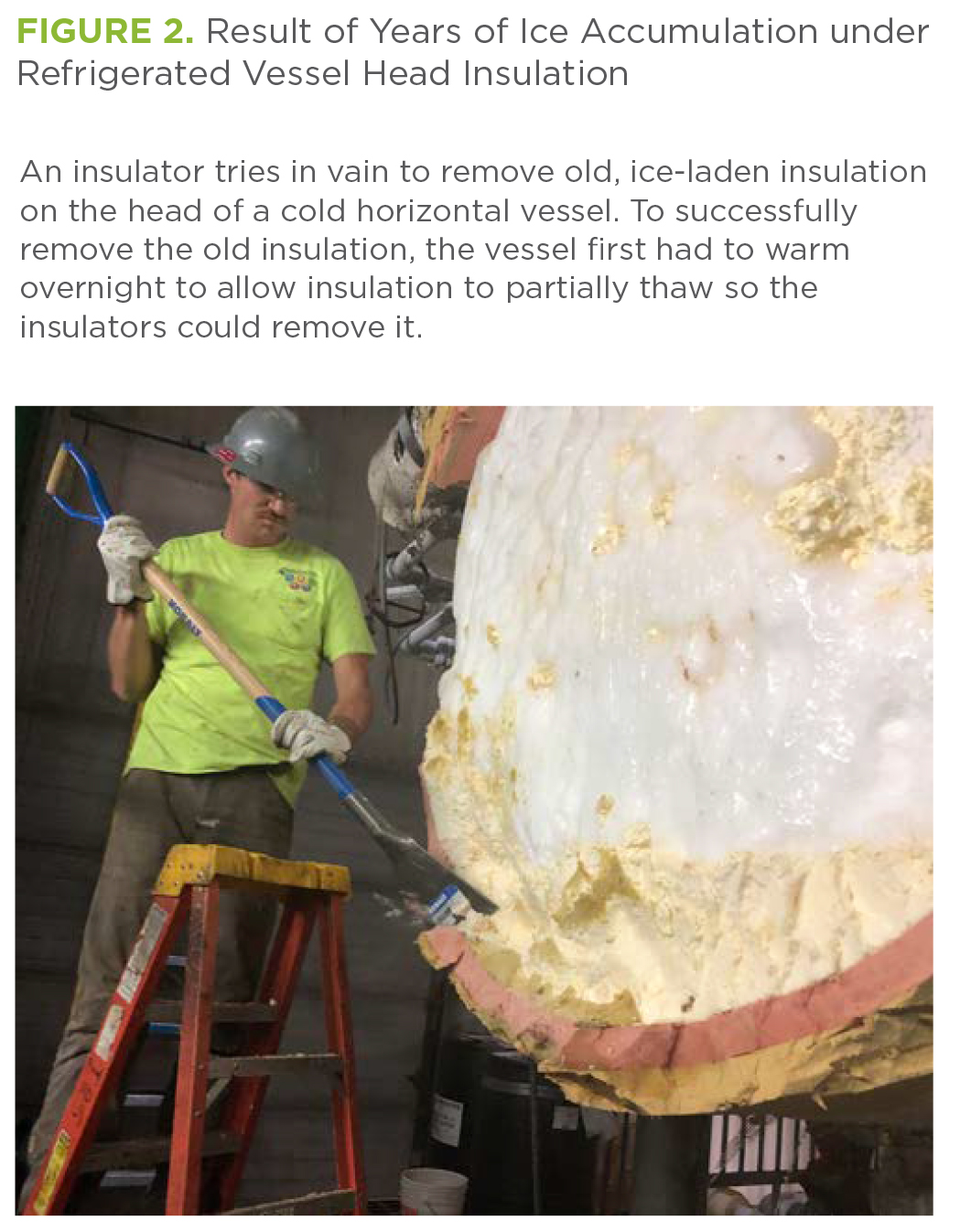
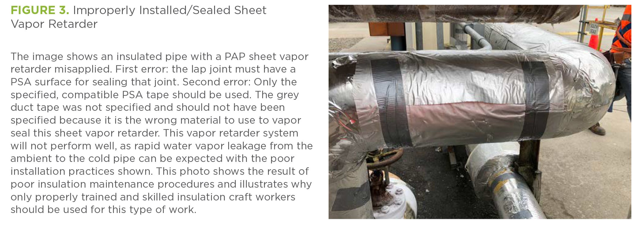
Figures 1 through 4 show the results of a major design error, installation error, or both. Figure 1 shows the results of years of ice accumulation in the pipe insulation on a refrigerated pipe. Figure 2 shows the results of years of ice accumulation underneath a refrigerated vessel head insulation. Figure 3 shows how not to install and seal a sheet vapor retarder (i.e., using the wrong type of pressure-sensitive adhesive [PSA] tape and installing tape perpendicular to the lap joint, rather than parallel to it). Figure 4 shows ice buildup on an uninsulated pipe section, also with no apparent vapor retarder.


How to Design a Refrigeration Insulation System Correctly
In a nutshell, a correctly designed refrigeration insulation system has the following components: (1) a corrosion-inhibiting gel applied to the carbon steel surface; (2) a low thermal conductivity, rigid insulation material with suitable joint sealant to seal the outer-layer pieces; (3) a low-permeance, water-resistant sheet or film vapor retarder with matching PSA tape; and (4) a protective jacket suitable for the exterior environment (i.e., indoors or outdoors).
Corrosion-Inhibiting Gel
These gels have no ASTM or other industry standard, so their performance needs to be assured by the manufacturer, of which there are several. Regardless, a thin layer of this pasty material, which is chemically reactive with the carbon steel, will—according to the manufacturers—stop any existing corrosion that has already started and prevent any future corrosion. These materials reportedly have a maximum use temperature of about 300°F, so they are not suitable for high-temperature systems but are suitable for ammonia refrigeration systems.
Low Thermal Conductivity, Rigid Insulation Material with Suitable Adhesives
On the projects in the study receiving new insulation systems, two types of insulation material were used: XPS per ASTM C578, Type XIII; or PIR per ASTM C591, Type II (ordinarily). These insulation materials are sufficiently rigid to allow cutting and routing, when necessary, and they have a sufficiently high compressive resistance to enable them to support pipes carrying ammonia refrigeration, when a pipe support is necessary. Note that both materials have relatively high water vapor permeability values, greater than 1 perm-inch. Hence, by themselves, they will not have particularly low permeance values and will have to be covered with well-sealed sheet or film vapor retarders to prevent water vapor migration to the cold steel surfaces, with subsequent condensation to water and/or ice. (More on that later in this article.) Other insulation materials may be considered for these ammonia refrigeration applications, such as cellular glass or flexible elastomeric, but these insulation materials were not installed on the 20+ projects reviewed in the study. Cellular glass has a very low water vapor permeability but a somewhat higher thermal conductivity at a given temperature, and hence would require greater pipe insulation thicknesses than the plastic foams. However, properly sealed, it may not require a sheet or film vapor retarder. Flexible elastomeric insulation likewise will require greater thicknesses than the plastic foams and, in this author’s opinion, still would require a sheet or film vapor retarder for ammonia refrigeration temperatures, not typically applied to this type of flexible insulation.
Low-Permeance (≤ 0.01 Perms) Sheet or Film Vapor Retarder with Matching Tape
ASTM C1136, Types VII and IX are low-permeance vapor retarders made of either PVdC or PAP, respectively. They are commercially available with matching tape that has a factory-applied PSA. Both of these materials are water resistant; hence, any condensation on their surfaces will not be absorbed as it would be on vapor retarders with an exposed paper surface, such as conventional ASJ. The matching tapes are typically 3 inches wide, but they can be obtained with a 4-inch width if necessary.
Protective Jacket
On the projects studied, protective jackets always consisted of 20 mil-thick polyvinyl chloride (PVC) for interior, machine-room applications; and 0.016 inch-thick (minimum) aluminum jacketing, per ASTM C1729, and aluminum banding. Screws and rivets are never specified because they would puncture the sheet or film vapor retarders during installation, destroying them in the process.
Industry specifications, such as that of the IIAR, and project specifications typically give installation details that ensure performance of the installed refrigeration insulation systems. Those are addressed in the next section of this article.
How to Correctly Store and Handle Refrigeration Insulation Materials
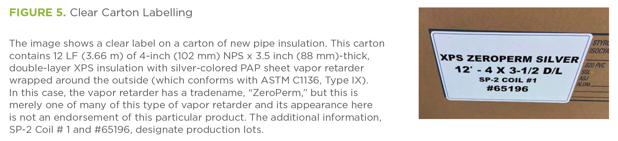
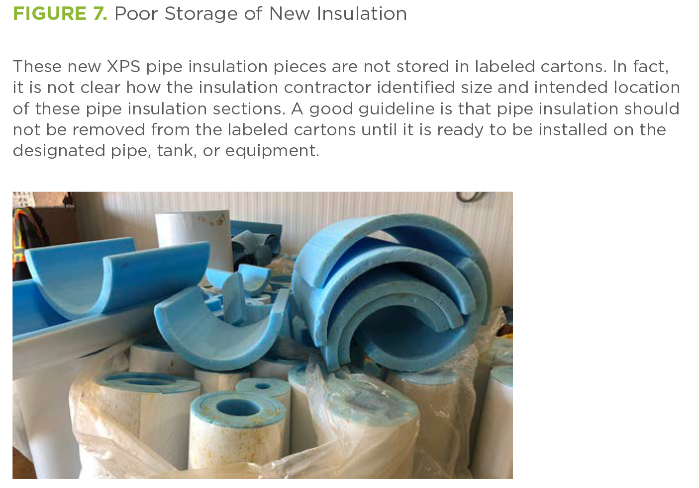
The insulation sections should be clearly labeled and packaged in cartons that protect them. The insulators will rely on the accuracy of the packaged insulation pieces when transporting them to the rooftop or equipment room of a facility. Figures 5 and 6 show how to do this correctly. Lack of clearly labeled cartons can result in a lot of confusion as well as damaged insulation pieces, as shown in Figure 7, which is unacceptable. [Note that appearance of the name “ZeroPerm,” a trade name, does not imply endorsement of that product by either the author or NIA.]

How to Correctly Install a Refrigeration Insulation System on Pipes
Old steel pipe and equipment must have a clean surface free of corrosion. If corrosion is present, the corrosion first should be removed with a rotating steel brush or similar tool. This work is generally done by the refrigeration contractor; but if it has not been, the insulation contractor should ensure that it is done prior to insulating. On new construction or existing construction with new pipe and equipment, the surfaces should be clean from the beginning.
The next step is for the insulators to apply a thin layer of corrosion-inhibiting gel, per the manufacturer’s instructions. Once this is done, the insulation materials can be installed. Figure 8 shows XPS pipe insulation, with fabricator-installed vapor retarder film, partially installed on a pipe that has first had a layer of corrosion-inhibiting gel applied.
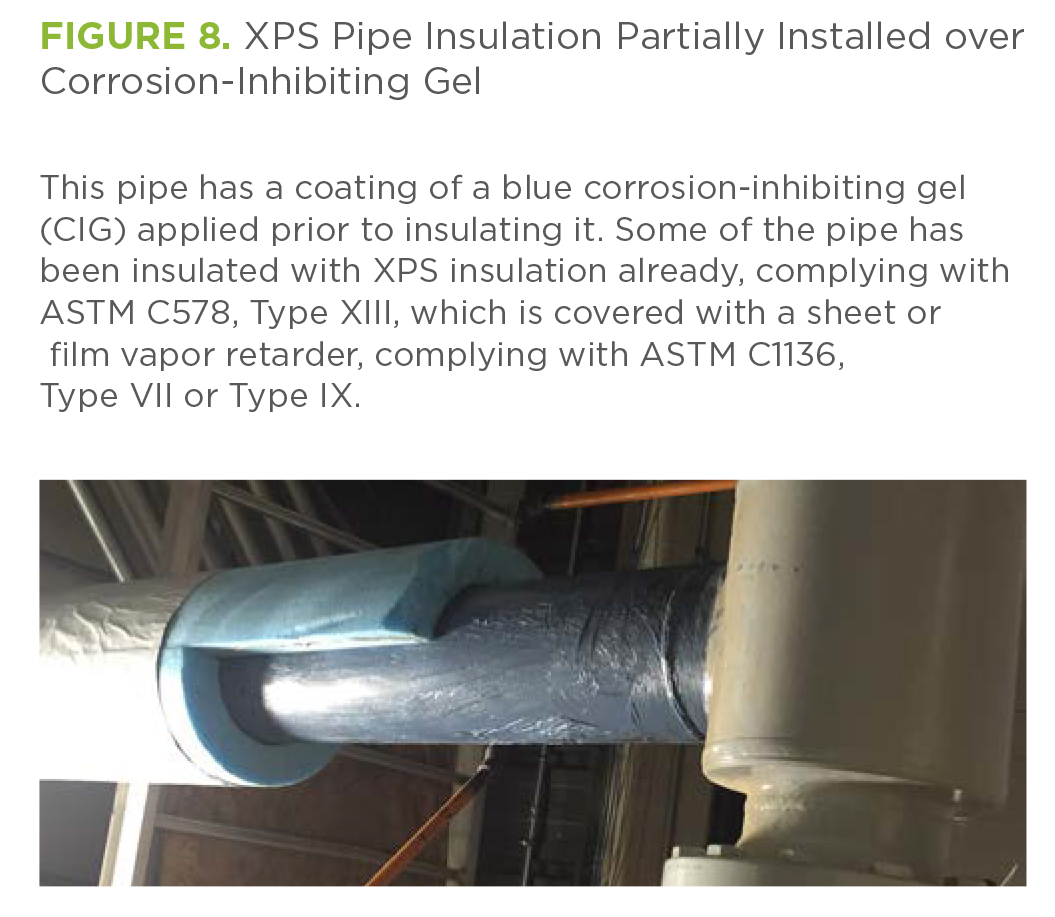
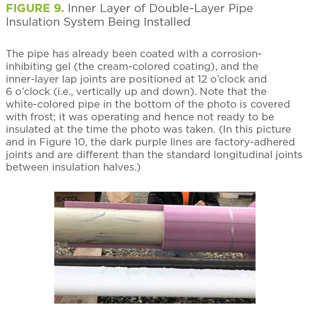
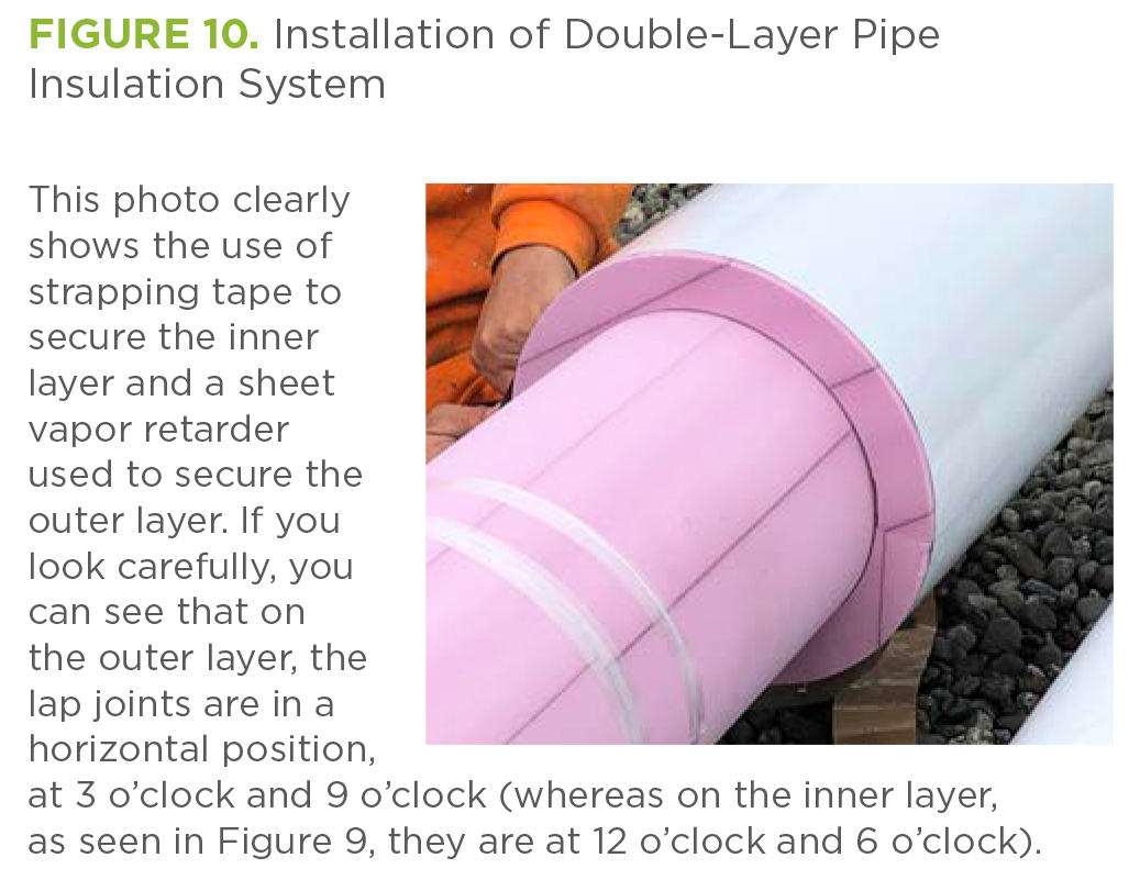
Figure 9 shows the inner layer of a soon-to-be double-layer XPS system being installed over a pipe that has first had the corrosion-inhibiting gel applied. Because Figure 9 shows only the first layer, there is no vapor retarder yet visible. The second layer will have the vapor retarder pre-applied to its outer surface. Figure 10 shows the second XPS insulation layer being installed, including the vapor retarder. In Figures 8 through 10, note that the joints
are staggered.
When installing pipe and equipment insulation, the outer insulation layers should be sealed with a low-permeance joint sealant. Figure 11 shows grey joint sealant being applied to the longitudinal joints of a single insulation layer system, and Figure 12 shows the pipe insulation after the two halves have been wrapped around the pipe and the sheet vapor retarder attached along the lap joints. Note that the XPS pipe insulation halves are already covered with a sheet vapor retarder, used to secure the insulation to the pipe.
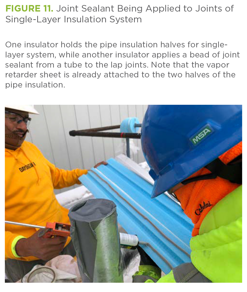

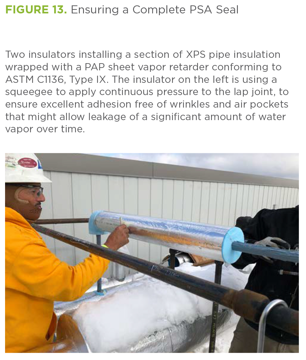
Figure 13 shows an insulator using a squeegee to apply pressure to the vapor retarder lap joint. This step ensures that the PSA seal is complete. Note that this pipe has a layer of corrosion-inhibiting gel on its surface. Figure 14 shows an insulator applying the 3 inch-wide PSA tape to a butt joint. Note that the butt joint has already had a grey joint sealant applied.

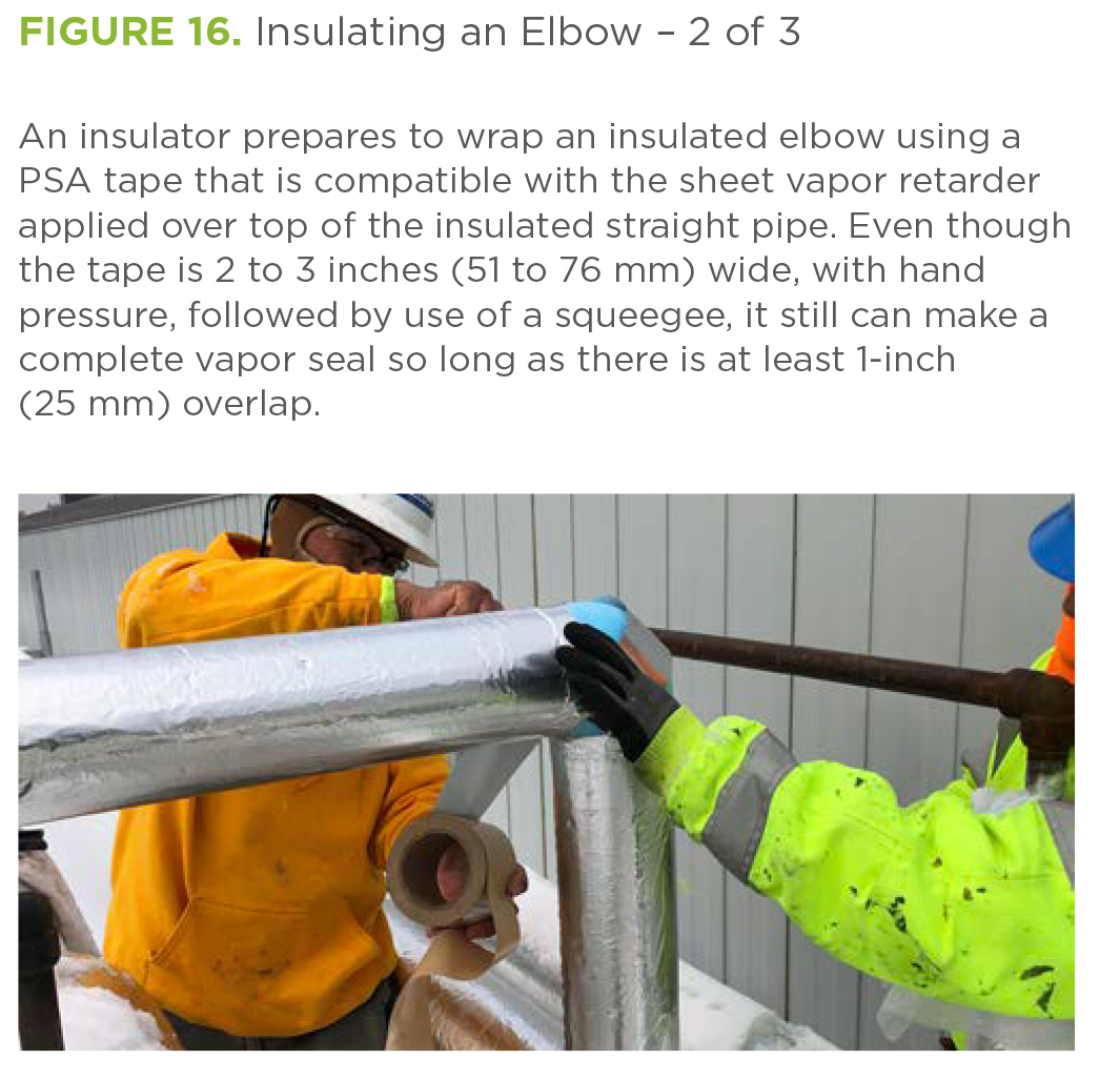
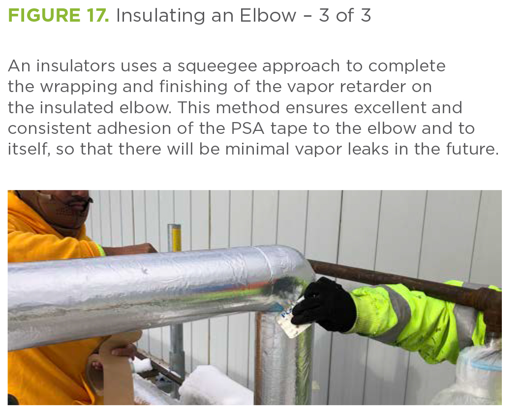
Elbows are insulated in a similar fashion, although the low-permeance PSA tape can be applied after the insulation has been installed over the elbow. Again, joint sealant should be applied first to the insulation piece mating surfaces before installation on the elbow. After covering the installed pipe with sealed insulation half pieces, it must be wrapped thoroughly with PSA tape to ensure that water vapor will not migrate into the insulation. Insulators should press the taped surfaces with a squeegee to make sure the surfaces are well sealed against water vapor intrusion. These steps are shown in Figures 15 through 17.

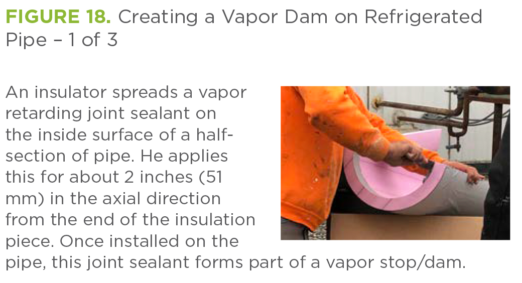
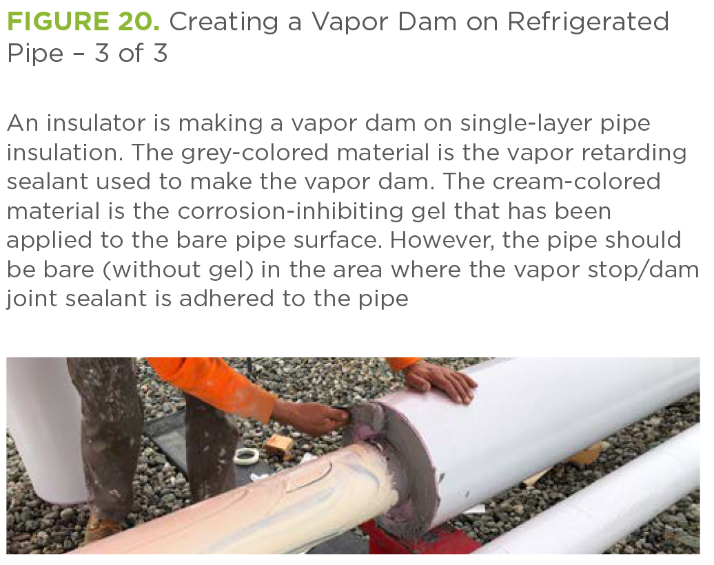
Vapor dams are specified and designed as a sort of insurance policy. If there is leakage through the insulation system to the bare pipe, water vapor will intrude and damage some of the insulation material. Vapor dams installed along pipes at some maximum distance from one another (I recommend 18 feet maximum) limit the vapor damage to that section. Figures 18 through 20 show how to properly make vapor dams on refrigerated pipes as a new insulation system is installed, using a low-permeability joint sealant.

How to Correctly Install Refrigeration Insulation Systems on Vessels
As with installing insulation systems for refrigerated pipes, the insulation systems for refrigerated vessels should be prefabricated. However, sheet or film vapor retarder
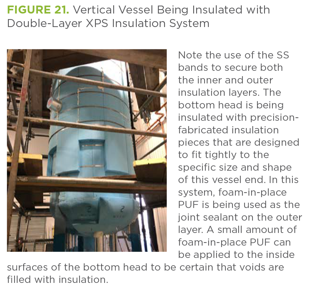
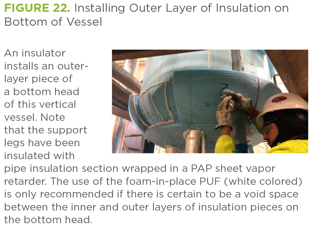
material should be installed and sealed, using matching tape, after the insulation pieces have been installed. Figures 21 through 23 show how to correctly install a double-layer insulation system prior to installing the vapor retarder. Note that SS bands are used to secure each insulation layer and that only the outer layer needs to be sealed with joint compound. The use of a liquid polyurethane foam is optional; however, to prevent excess heat gain, it is important to fill all gaps and voids using this polyurethane foam (PUF) insulation material.

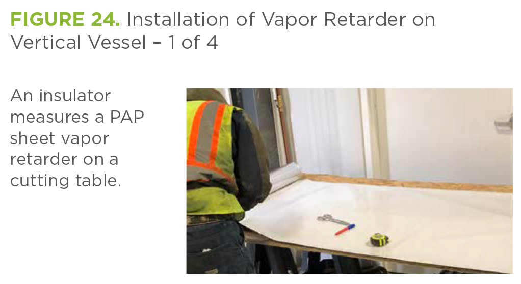
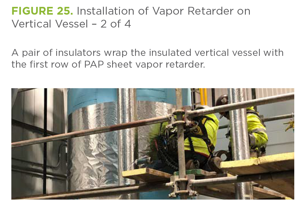
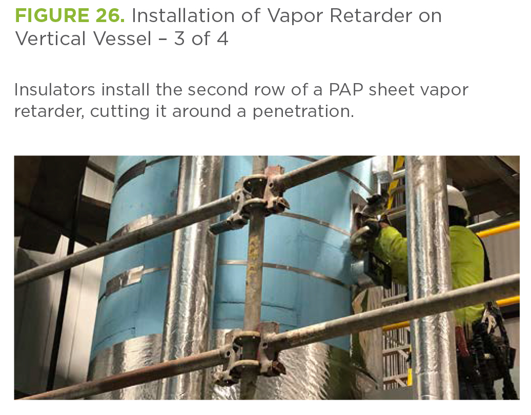
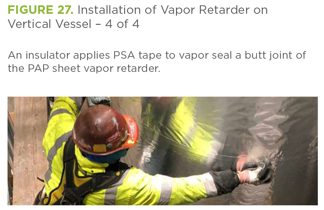
The installation of a sheet or film vapor retarder, as shown in the following Figures 24 through 27, should be done with patience and attention to detail. It is critical to install this material without tearing or puncturing it, sealing all joints with the matching PSA tape and pressing all taped joints with a squeegee to ensure excellent adhesion and sealing.
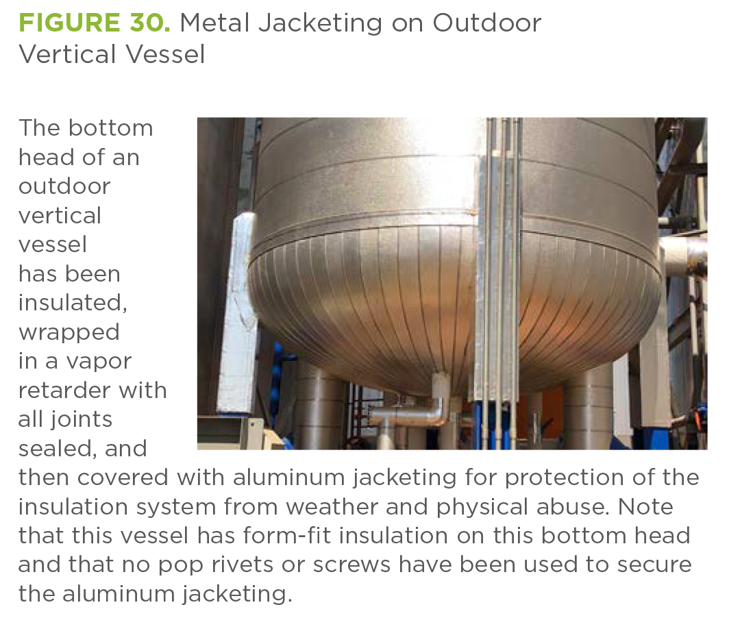
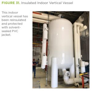
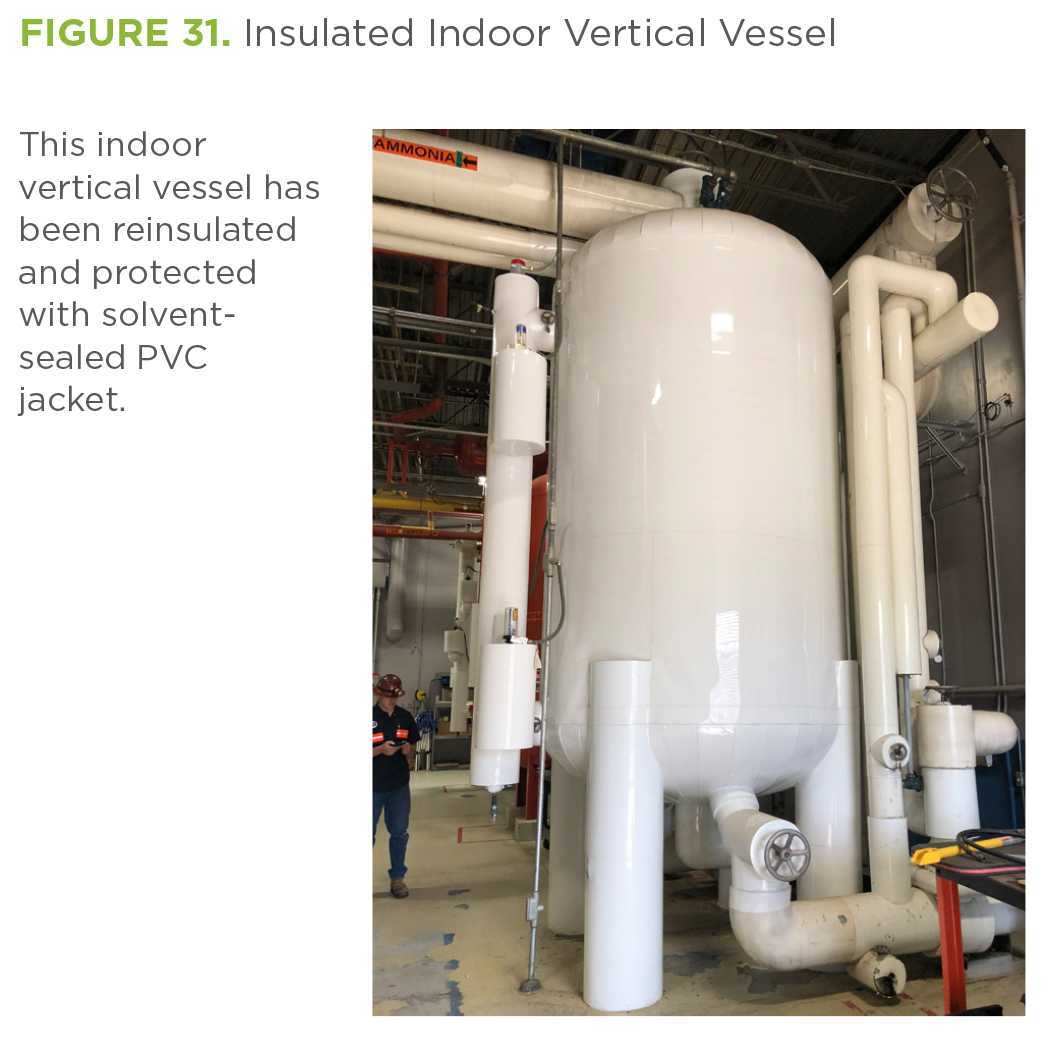
Correct Installation of Protective Jacketing over Refrigeration Insulation
After protective jacketing has been installed over refrigeration insulation, it is generally impossible to know whether the insulation system has been designed and installed correctly or not just from looking at it. However, whether installing PVC jacketing in equipment rooms or aluminum jacketing on outdoor rooftops, one huge error can be easily detected: Have the insulators used screws and/or rivets to secure the jacketing? If those have been used, they will have punctured the sheet or film vapor retarder, rendering it useless (since ambient water vapor will rapidly migrate through those punctures). For indoor PVC, solvent sealing of joints should be sufficient to secure it; for outdoor aluminum jacketing, SS bands with wing seals should be sufficient.
Rooftop ammonia lines are generally relatively long (i.e., several hundred feet), with only pipe supports being the main disruptions. Equipment room ammonia lines are generally short (i.e., 10 to 20 feet long), with lots of supports. In both cases, the protective jacketing must be installed in such a way as to respect the integrity of the sheet or film vapor retarder, since the performance of the entire systems depends upon the long-term performance of the water-resistant sheet or film vapor retarder, including its being sealed at joints and around interruptions.
Figures 28 and 29 show the results of the correct installation of rooftop ammonia pipe insulation, with the sheet vapor retarder exposed in Figure 28 (because it has not yet been covered).
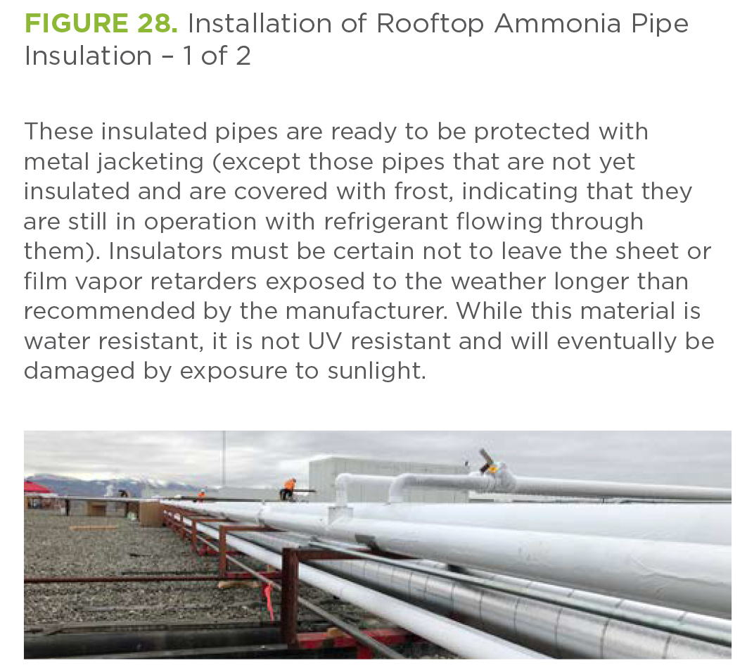

Figure 30 shows the completed metal jacketing, and Figure 31 shows the completed PVC jacketing—the former located outdoors and the second showing the completed installation indoors.
Conclusion and Recommendations
The correct design and installation of industrial refrigeration insulation systems requires attention to detail. To ensure long-term performance of the insulation system, water vapor must be prevented from migrating from the ambient into the insulation, where it will condense to water and/or ice, resulting in severe damage to the insulation materials and significantly reduced thermal performance. Sheet or film vapor retarders should be water resistant, have a water vapor permeance ≤ 0.01 perm, and be tightly sealed everywhere. Any tears or punctures must be repaired prior to installation of protective jacketing. Over time, the facility owner must maintain the insulation system, ensuring its performance with regular inspections. Repairs should be made as soon as possible, and only by trained, experienced, and qualified insulators who are familiar with insulating refrigerated pipe and equipment.
References and Bibliography
- G. H. Hart, “Case Study: Economic Justification for Replacing Ice-Laden Refrigerant Pipe Thermal Insulation with New Insulation,” in Proceedings of the IIAR 2015 Industrial Refrigeration Conference, San Diego, California (Alexandria, VA: International Institute of Ammonia Refrigeration, 2015).
- G. H. Hart and C. Bludau, “Hygrothermal Analyses of Ammonia Refrigeration Pipe
Insulation Systems,” in Proceedings of the IIAR 2016 Industrial Refrigeration Conference, Orlando, Florida (Alexandria, VA: International Institute of Ammonia Refrigeration, 2016). - Standard Specification for Rigid, Cellular Polystyrene Thermal Insulation, ASTM C578-19 (West Conshohocken, PA: ASTM International, approved June 1, 2019), http://doi.org /10.1520/C0578-19
- Standard Specification for Unfaced Preformed Rigid Cellular Polyisocyanurate Thermal Insulation, ASTM C591-21 (West Conshohocken, PA: ASTM International, approved April 15, 2021), http://doi.org/10.1520/C0591-21
- Standard Specification for Flexible, Low Permeance Vapor Retarders for Thermal Insulation, ASTM C1136-21 (West Conshohocken, PA: ASTM International, approved March 1, 2021), http://doi.org/10.1520/C1136-21
- “Insulation for Refrigeration Systems,” in Refrigeration Piping Handbook (Alexandria, VA: International Institute of Ammonia Refrigeration, 2019), 7-1–7-63.
- Standard Test Methods for Water Vapor Transmission of Materials, ASTM E96/E96M-16 (West Conshohocken, PA: ASTM International, approved March 1, 2016), http://doi.org /10.1520/E0096_E0096M-16
- Standard Specification for Aluminum Jacketing for Insulation, ASTM C1729-21 (West Conshohocken, PA: ASTM International, approved March 1, 2021), http://doi.org/10.1520 /C1729-2
- G. H. Hart, “Development of a Mechanical Insulation Installation Guideline for Refrigeration Applications,” in Proceedings of the 42nd Annual Meeting of the International Institute of Ammonia Refrigeration (IIAR), Orlando, Florida, March 15–18, 2020.
Gordon H. Hart provided all photos for this article.