An Industry Perspective: Revisiting Recommendations
Corrosion under insulation (CUI) is the corrosion found under thermal insulation and fireproofing materials. It most commonly results in metal loss, rusting (see Photo 1), or cracking of the insulated components (see Photo 2). It can foul bolt threads, lock critical valve stems, crack instrument tubing, and otherwise interfere with routine plant operations. CUI results in major equipment outages, production losses, and unexpected maintenance costs in refineries and chemical processing plants.
While CUI has occurred as long as hot and cold equipment has been insulated, it was not discussed in scientific journals until the 1950s, and the extent of this damaging corrosion problem was not widely recognized and seriously examined until the 1980s.
The National Association of Corrosion Engineers (NACE International), the American Society for Testing Materials (ASTM), and the Materials Technology Institute (MTI) held a joint symposium on this subject, with speakers from industries worldwide. There was an open discussion on such CUI topics as corrosion mechanisms, methods for mitigation, insulation materials, and inspection. Comparing the various approaches, it was evident that there were many similarities. Most of the attention up to that time had been on bettering the individual components that make up an insulated system. For example, paint manufacturers were concerned with the best paint to apply under the insulation, insulation manufacturers were discussing the merits of cellular glass versus calcium silicate, insulators were concerned about vapor barriers and aluminum versus stainless steel jacketing, and plant inspectors were looking for cost-effective methods to find CUI.
Members of NACE International eventually developed a consensus document to recommend current technology and industry practices for mitigating CUI. Industry representatives on the committee charged with developing the document were from firms producing, specifying, designing, and using thermal insulation and fireproofing products on refinery and petrochemical equipment and piping. The result was the NACE Recommended Practice RP0198-98, “The Control of Corrosion Under Thermal Insulation and Fireproofing Materials—A Systems Approach.”
Although most attention has been focused on corrosion under thermal insulation, fireproofing materials also function—at least in part—as insulation applied between the critical steel structure and a potential fire. A discussion of corrosion mechanisms, the root cause of failure, and corrosion prevention was considered to be the same for corrosion under both insulation and fireproofing in RP0198-98.
The document includes the following six sections:
- Section 1—a general introduction to the scope of the problem
- Section 2—an explanation of the CUI corrosion mechanisms
- Section 3—examples of mechanical design for water-shedding insulation systems
- Section 4—a discussion of protective coatings for the insulated components
- Section 5—information on insulation and fireproofing materials
- Section 6—recommended inspection and maintenance practices
Along with a brief introduction to CUI, Section 1 provides background on past technical approaches to solving the problem.
In its detailed discussion of CUI corrosion mechanisms, Section 2 addresses the two main alloy families affected by CUI: carbon steels and austenitic stainless steels.
Carbon steels corrode, and stainless steels crack—not because they are insulated, but because they are contacted by aerated water. The role of insulation in the CUI problem is threefold. Insulation provides: 1) an annular space or crevice for the retention of water and other corrosive media; 2) a material that may wick or absorb water; and 3) a material that may contribute contaminants that increase or accelerate the corrosion rate.
The corrosion rate of carbon steel and the likelihood of stainless steel cracking vary because they are controlled largely by the temperature of the metal surface and the contaminants present in the water.
Effects and Sources of Water and Contaminants
Given that it is virtually impossible to exclude water from an insulated system, temperatures’ effects play the major role in determining the extent of the corrosion. Figure 3 describes the corrosivity of water in the CUI temperature range.
Inspection of equipment has shown that carbon steel operating in the temperature range of 4°C (25°F) to 150°C (300°F) is at the greatest risk of CUI. Equipment that operates continuously below -4°C (25°F) usually remains free of corrosion, and corrosion of equipment operating above 150°C (300°F) is reduced. However, corrosion often occurs at those points of water entry into the insulation system where the temperature is below 150°C (300°F), at the ice-to-wet transition zones, in equipment in cyclical services, and when the equipment is idle.
As for austenitic stainless steels, the NACE document notes that external stress corrosion cracking (ESCC) “occurs in austenitic stainless steel piping and process equipment when chlorides or other halides in the environment or insulation material are transported in the presence of water to the hot surface of stainless steel and are then concentrated by evaporation of that water. This most commonly occurs beneath thermal insulation, but the presence of insulation is not a requirement. Thermal insulation primarily provides a medium to hold and transport the water with its chlorides to the metal surface.”
Like carbon steel, the temperature range at which ESCC of stainless steels is most likely to occur is not firmly established, but it is generally accepted to be 50° to 150°C (120° to 300°F). Failures are less frequent when metal temperature is outside this range. Below 50°C (120°F), the reaction rate is low. Above 150°C (300°F), water is not normally present on the metal surface and failures are infrequent. However, equipment that cycles through the water dew point is particularly susceptible.
Mechanical Design of the Insulation System
A poorly designed or installed insulation system, or one with penetrations through the insulation, permits water intrusion into the system. Water also enters the system when vapor barriers, weather barriers, mastics, and sealing caulked joints break down over time.
The life of insulated systems can be significantly extended by better design to limit protrusions, attachments, and supports associated with vessels
and piping.
The mechanical design section of the NACE document discusses specification requirements and common specification flaws to be avoided, such as incorrect application of materials, product specification that does not state the properties required, and improper or unclear application methods. The section also discusses the key components of a properly designed insulation system. Drawings are provided to illustrate design do’s and don’ts.
The NACE document then covers how to select protective coatings for carbon steel and austenitic stainless steel. Attempts to prevent water from entering insulated systems though rigorous application of mechanical design principles have not been successful; and corrosion-protection techniques, such as inhibitors and cathodic protection, have been less effective than protective coatings in mitigating CUI. Protective coatings have been recognized and accepted as a highly effective method of protecting insulated metallic substrates from corrosion.
Thus, the consensus is that the basic solution for CUI prevention is the use of a high-quality protective coating. The committee recommends that whenever CUI is a consideration, a protective coating should be employed to protect the equipment before it is insulated. What coating system is most appropriate for protecting the metallic substrate depends on whether carbon steel or stainless steel is being insulated, and on the temperature range of the metal.
Four protective coating systems are listed for austenitic stainless steels. High-build epoxy is recommended for applications in the temperature range of -50° to 140°F. For high-temperature applications to 700°F, modified silicone coatings are recommended. In addition to the coatings, heavy-gauge, aluminum-foil wrapping has been successfully used to prevent ESCC.
With carbon steels, tank lining systems formulated to prevent corrosion are typically recommended for use on steel operating below 150°C (300°F) under thermal insulation. Additional coating systems are recommended for higher operating temperatures. In all, 11 traditional coating systems and a thermally sprayed aluminum coating are recommended in the document.
The Full Range of Factors That Affect An Insulating System
“Users who steam-purge lines shall select a coating capable of withstanding the surface temperature for the duration of the purging. The coating manufacturer should be consulted for specific temperature-resistance information,” the NACE document states.
Another warning concerns inorganic zinc: “Inorganic zinc coatings or galvanizing shall not be used under thermal insulation in the 50°-to-150°C (120°-to-300°F) service temperature range for long-term or cyclic service. Zinc provides inadequate corrosion resistance in closed, sometimes wet environments.”
Section 5 of the NACE document covers insulation, fireproofing, and accessory materials. It describes the properties of industrial insulation, accessories for insulation, and fireproofing materials that affect corrosion. The emphasis of this section is on service performance at specific operating temperatures and the system’s ability to exclude water over the life of the system.
The insulation materials covered in this section include the following:
- Calcium silicate
- Expanded perlite
- Man-made mineral fibers
- Cellular glass
- Organic foams
- Ceramic fiber
- Historical materials
The section addresses ASTM qualification tests for insulation that is used over stainless steel materials and chlorine content test methods.
Insulation accessory materials include components used to fabricate insulation materials into shapes that fit pipes and equipment, as well as those used to apply the shapes, provide weatherproofing, and seal projections through the insulation system.
In the long term, weather and vapor barriers break down or are damaged to the point that they can no longer keep the insulation dry. So maintenance and inspection of weatherproofing are essential to ensure the integrity of the insulation and fireproofing system. Section 6 addresses inspection and maintenance issues, and presents a checklist of inspection details for new construction.
Insulation on process equipment creates a significant barrier to inspection to detect and assess CUI. Removing all insulation on susceptible equipment is the only way to find all areas affected by corrosion. But this is expensive and may not be practical or allowed for operating equipment. Removing insulation may adversely affect operating conditions.
The section also discusses methods for developing a cost-effective inspection program to mitigate CUI. Factors to be used in determining at-risk equipment include the following:
- Age of the equipment
- Type of protective coating on the metal under the insulation
- Equipment location
- Operating temperature
- Construction materials
- Consequences of a leak
Once the high-risk equipment has been identified and an inspection work plan developed, trained inspectors should conduct a visual examination following the key indicators for CUI listed in this section of the NACE document. Additional nondestructive examination techniques to enhance, but not replace, the visual inspection also are listed.
It is clear that a systems approach to controlling CUI is necessary. With the use of modern coatings technology, selection of appropriate insulation materials, and good installation practices, it is reasonable to expect cost-effective insulated piping and equipment to provide 20 to 30 years of reliable performance.
 Figure 1
Photo 1
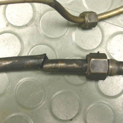 Figure 2
Photo 2
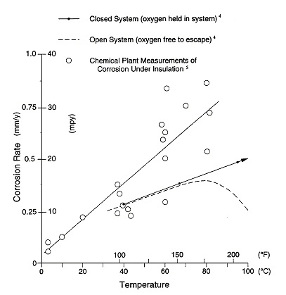 Figure 3
Figure 3