Auditing for Efficiency
An energy audit can mean many things to many different people. For some, an energy audit (sometimes referred to as an energy assessment) means focusing on processes (steam traps), operations (lights and computers), or equipment (motors). These areas are all worthwhile and offer companies an opportunity to save energy as it relates to steam, heat, or electrical output. Energy savings can also be applied to lowering the amount of energy required to make electric power.
President George W. Bush said, "Energy is a problem that requires action; not politics, not excuses, but action." Obviously, the action to which Bush referred should be applied to industries that use the most energy, the steam and power-generating industries. This energy is fuel (oil, gas, coal, refuse) and is used to make electricity. Brick, refractory, and insulation on any steam-generating unit when properly designed and installed will save as much as 5 percent to 7 percent percent in annual fuel cost. Therefore, brick, refractory, and insulation have a direct effect on the energy consumption of a steam-generating boiler.
Example of Potential Savings
The Lawrence Berkley National Lab recently reported the estimated the life-cycle cost of a typical industrial boiler unit. It was discovered that, with a $165,000 capital cost and 20-year life, operating 7,000 hours per year, the typical industrial boiler unit uses $8 million dollars of fuel (oil, gas, coal, refuse) over its lifetime.
Based on our estimates of 5 percent, the energy savings would amount to approximately $500,000 over the life of the boiler, assuming, of course, that its brick, refractory, and insulation were properly designed and installed. Brick, refractory, and insulation are key components of any steam-generating boiler, and when properly designed and installed can last 20 years or more.
The boiler used as an example of fuel consumption by Lawrence Berkley National Lab is quite small, yet the premise for energy savings can apply to any steam-generating boiler, regardless of size. For example, a new hopper bottom boiler that was recently built in St. Paul, Minn., has a furnace box size of 25 ft x 24 ft x 79 ft and a capital cost of more than 4 million dollars. The brick and refractory for that particular industrial boiler was estimated to cost $130,000. The amount of fuel it will consume over a 20-year life would be far greater than the small package boiler that Lawrence Berkley was talking about and so too would be their energy savings. (The exact numbers and fuel cost were not available as the unit is too new.)
Unfortunately, most people don’t pay attention to their brick, refractory, and insulation. For example, when brick and refractory fail, you can expect many costly problems. Fly ash fills the penthouse and vestibules, hot spots begin to show up on the cased wall areas, fuel consumption rises, and, in some cases, the boiler will have to be shut down.
In this article, we will provide an example of an energy audit at a very large power-generating facility.
Background Information
The energy audit was performed on a 550-megawatt steam-generating boiler built in 1961 that was designed to be a combination tangential boiler* (on the furnace roof) and a membrane boiler*. It has 60 XCL-type burners, uses pulverized coal as its fuel and has a furnace box size of 32 ft x 72 ft x 128 ft. Prior to this energy audit, fly ash had to be removed from inside the entire penthouse* and wind box* areas because it had completely filled these two areas. (See box at top left of page 9.)
The Energy Audit
The energy audit’s objective was to review and assess the condition of the brick and refractory materials in all areas of this large steam-generating boiler. In addition, comments were needed on the condition of the insulation used on the gas turbine and super heater tube legs and headers inside the penthouse.
To do that, it was necessary to:
- Review all the drawings (boiler settings, super heaters, burners, doors, wall boxes, roof tube arrangements, boiler and furnace wall tube arrangements) where the brick and refractory materials were to be found on this boiler. This amounted to looking at almost 100 original and alteration-type construction and detail drawings.
- Do a complete review of the brick, refractory, and insulation specifications (material and labor) of the boiler. The original equipment manufacturer (OEM) should have provided this information at the time the boiler was built. This review also included any field modifications to the OEM’s brick, refractory, and insulation requirements on this boiler.
- Create an Approach Map (like a road map) to know where to go and what to find in any given area (material type, construction, quantity, square foot area) on the boiler.
Using the Approach Map as a guide, all areas of the boiler from the trough seal at the bottom of the boiler to the roof seals were inspected. At each specific location digital photographs were taken, pertinent field observations and data recorded, and in some cases material samples taken. Much can be ascertained by looking at the condition of the brick, refractory, and insulation as it exists on a steam-generating boiler. An experienced eye can tell, for example, if the brick and refractory were properly installed, how it was installed, if it was properly mixed, if it was cured or dried, and why it failed. For this particular audit, only those areas that truly impacted the energy and steam efficiency of the boiler will be discussed.
Audit Area I – Burner
There are a total of 60 coal-fired burners on the boiler and they are by far the most energy-intensive area of the boiler. These burners require proper airflow in and around for fuel efficiency. The angle or contour of the throat area is critical for burner/fuel efficiency (stochiometry of the burner-stochiometry is the ratio of the amount of air to the burners to the amount of fuel. If the stochiometry is not right then the burner flame can get longer, there may be excessive turbulence in the flame, temperature variances, and/or an increase in ash content.)
Revealed by the Audit:
The burner throats inside the furnace were improperly installed. Most of the burner throats had missing plastic refractory material that left tubes and pin studs exposed to the burner flame. The contour of the throat made by the plastic refractory was not at the proper angle as required by the burner drawings. The missing plastic material and the improper contour of the throats had a major impact on the efficiency of the burners.
Recommendation:
It was recommended that the existing plastic refractory material be removed and replaced with a 60 percent alumina air bonded plastic material, making sure that the contour of the burner throat formed by the plastic material is at the proper angle 25 degree angle.
The burner wall area inside the wind box had exposed openings between the throat area and the membrane tube walls. These open areas were supposed to be sealed with a refractory material. Each burner had on average eight openings into the furnace, allowing gas and ash to penetrate into the wind box. This explains how the fly ash got into the wind box and would add to the inefficiency of the burners.
Recommendation:
The partial removal of the refractory around the junction point between the burner throats and the membrane tube wall and adding of new anchors, expanded metal lath and refractory around the perimeter of the burner throats and furnace wall. This would prevent future gas and ash penetration and allow proper airflow around and into each burner for proper combustion of the fuel.
Audit Area II – Super Heater Floor Seal
General Information:
This is a high erosion or abrasion area that’s located between the furnace area and the convection pass or heat recovery area of the boiler. It’s also a critical area for steam efficiency. The refractory seal that is located at the top of the sloped floor ensures proper gas flow and heat distribution for the re-heater tubes located inside the convection or heat recovery area of the boiler. Without a proper refractory seal, the flue gas is misdirected and would bypass the re-heater tube sections. This would also expose the super heater floor and screen tubes to abrasion from the flue gas and the particulates that are in it.
Revealed by the Audit:
The refractory in this area was almost completely water-washed away. There was no visible sign of any refractory support system installed as per the original equipment manufacturer’s specifications and drawings. The refractory that was installed hadn’t been installed correctly, as evidenced by the refractory covering the top of the refractory barrier plate and lacking an anchor or support system. There were also large open areas that would allow the flue gas to bypass the re-heater tube sections.
Recommendation:
A complete removal of all remaining refractory material in the tube seal area. Then, add new support material (expanded metal lath) and use a high strength refractory material with stainless steel needles for added strength. The support system, needles, and high strength refractory would help keep the seal in place during future water wash downs as well as help assure proper flue gas flow into the heat recovery area of the boiler. In other words, the flue gas would flow over the top of the seal and down over the top of the re-heater sections to maximize heat recovery for steam efficiency.
Audit Area III – Tile Gas Barriers
General Information:
This is another critical area that’s very important for steam efficiency. The tile baffles located in the convection pass or heat recovery area of the boiler ensure proper gas flow and heat distribution for the re-heater tubes that are located inside the convection or heat recovery area. Without these tile baffles, flue gas would pass around instead of over and through the re-heater tube sections. The misdirection of the gas flow would also cause erosion of the re-heater tubes.
Revealed by the Audit:
The tile baffles were deteriorated in most of the locations, especially on the overhead areas. It was quite obvious that the tile baffles were not able to prevent the flue gas from passing down the open cavity at the ends of the re-heater tube sections.
Recommendation:
The total replacement of the tile barriers and the elimination of the tile barriers on overhead areas, which were not needed for proper gas flow baffling. Also, setting each tile in an air-setting mortar. (The existing tiles had been laid loose without any mortar.)
Audit Area IV – Convection Pass Roof Tubes and Furnace Roof Tube Area
General Information:
This is another critical area of the boiler for steam and energy efficiency. The roof refractory ensures that the gas and fly ash stay inside the furnace cavity. If the refractory fails to do its job, the flue gas and fly ash will penetrate the penthouse area and cause extensive damage. (Remember that fly ash had to be removed from the entire penthouse prior to the Energy Audit.) Proper refractory roof construction will ensure that the boiler will use the least amount of fuel to achieve its steam and heat requirements, translating into major cost savings.
Revealed by the Audit:
Large cracks were found in the roof tube areas, allowing flue gas and fly ash to penetrate into the penthouse. These cracks occurred because the installing contractor used too small of an expanded metal lath (a lath with too small a size of the diamond openings) to support the refractory. The improperly sized expanded metal lath prevented the gun-applied refractory from penetrating down through the lath to the roof tubes for a gas-tight seal between the penthouse and the furnace area.
Another contributing factor was that the lath had not been welded to the roof tubes in many areas. This allowed the loose lath (and refractory on top of the lath) to float when the boiler was operating and gave easy access for the fly ash to enter the penthouse. Also, the refractory seal at the junction of the roof tubes and the sidewall tubes had not been installed. This side wall seal is vital for a gas-tight construction between the furnace cavity and the penthouse. When the boiler is put into operation the tubes expand and the corners, without any refractory seal, would allow hot gases (more than 2,000 degrees Fahrenheit) and fly ash to enter the penthouse. The higher-than-design temperatures inside the penthouse also caused serious structural damage to the tube and header supports.
Recommendation:
Using a larger size expanded metal lath (1 1/2 inch x 13 gauge) welded to the roof tubes for the proper support of the roof refractory. The larger size lath would also allow the refractory material to penetrate through the lath down to and between the roof tubes and give a good gas-tight seal. We also recommended the installation of the refractory corner seals at the junction of the roof tubes and side wall tubes. The proper installation of the refractory (and lath) on the roof tubes and adding corner seals would prevent any further gas and fly ash penetration into the penthouse and would help make the boiler more energy efficient.
Audit Area V – Super Heater Seal Penetrations
General Information:
The super heater seals are the most important for energy efficiency of any area found on a steam-generating boiler. The super heater tubes that pass through the roof tubes must be gas-tight to prevent the flue gas and fly ash from penetrating into the penthouse. Like the roof construction, the super heater seals will ensure that the boiler will use the least amount of fuel to achieve its steam and heat requirements, producing the biggest fuel cost savings.
Revealed by the Audit:
There was extensive damage and large open areas at all the super heater seal boxes. This showed that the refractory for the seal boxes were not installed correctly. The visual inspection revealed a number of installation mistakes: 1) a lack of expansion joints per specification in each layer of the refractory seal; 2) the refractory material had been gunned-applied with irregular thicknesses; 3) there were no indications that a parting agent had been used to keep the refractory from sticking to the super heater tubes. The cracking around the tubes was caused in many areas by the lack of a parting agent. The refractory failure allowed the flue gas and fly ash to penetrate into the penthouse area.
Recommendations:
1. Replace the seals per the original design.
2. Upgrade to a higher strength refractory.
3. Add expansion joints in the refractory seal design.
3. Add anchoring materials (lacing wire).
4. Use a parting agent on the super heater tubes.
5. Change the application for installing the refractory to a poured application in lieu of gunning. This would allow for the proper thickness of the refractory and allow for incorporation of the expansion joints in each layer of the seal.
Audit Area VI – Turbine Generating Insulation
General Information:
The insulation on the generating turbines is required due to the surface temperature of the turbine being more than 1,000 degrees F. Without the proper insulation materials and installation there will be extensive and valuable heat and steam lost. This is where a power plant makes its money. The insulation on the turbines is essential to prevent valuable heat loss.
Revealed by the Audit:
A ceramic fiber 2,300-degree-F blanket was used with a cloth-type cover so the insulation blankets could be reused. The condition of the outer finish of these blankets and the attachments used showed that the steam temperatures exceeded the temperature limits of the finish material. This wasn’t only burning up the cloth material and the attachments that hold the blanket together, but also allowing valuable heat to escape from the turbine surface. It was determined that the thickness of the removable blanket was inadequate and the temperature limits of the insulation material being used far exceeded the temperature requirements.
Recommendation:
1. Use a mineral wool 1,200-degree-F blanket meeting ASTM C-592 class II in lieu of the ceramic fiber blanket. The temperature limits didn’t dictate the use of a 2,300-degree-F product ceramic fiber product. This would save approximately $3 per square foot for every inch of insulation thickness required.
2. Increase the insulation thickness.
3. Use a higher-temperature blanket facing or cover material.
4. Use a higher temperature insulation attachment.
Audit Area VII – Super Heater Header and Leg Insulation inside the Penthouse Area
The super heater headers and legs operating above 850 degrees F must be insulated to keep the temperature inside the penthouse between 850-875 degrees F and to prevent excessive heat loss.
Without the proper materials and installation, there will be extensive and valuable heat and steam loss along with damage to the penthouse casing and structural damage to the penthouse itself.
Revealed by the Audit:
The condition of the structural steel inside the penthouse and the penthouse casing revealed that the temperatures inside exceeded the temperature limits of 875 degrees F. Though this could have been caused by refractory failures inside the penthouse, it was noted that the wrong insulation thickness (1 inch in lieu of the specified 1 1/2 inch) contributed to the damage done by the increased temperatures inside the penthouse.
Recommendations:
1. Use a mineral wool 1,200-degree-F blanket meeting ASTM C-592 class II in lieu of the ceramic fiber blanket. The temperature limits did not dictate the use of a 2,300-degree F product ceramic fiber product. This would save approximately $2 per square foot.
2. Increase the insulation thickness from 1 inch to 1 1/2 inch.
3. Use a higher temperature insulation attachment.
4. Add insulation supports to all top surface areas where the open space between the headers or tubes on the top surface exceeded nine inches wide.
Final Thoughts
The energy audit discovered some very specific areas that directly affected the amount of fuel used to meet heat and steam requirements. A boiler, regardless of size, will always use more fuel if the brick, refractory, and insulation are not installed correctly. After all the changes and corrections were made, it was estimated that the power plant can expect an annually savings of up to $100,000 in pulverize coal (energy) cost. This is why experts say, "Brick, refractory, and insulation installed to save energy also saves money at a rate that is essential for efficient plant operation."
References
- ASTM C-64
- Refractories in the Generation of Steam Power – McGraw-Hill Book Company, F. H. Norton (1949)
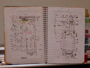 Figure 1
Sketch of an approach map
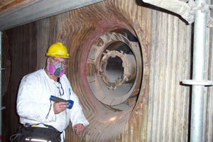 Figure 2
Burner throat being inspected
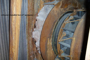 Figure 3
A burner inside a windbox
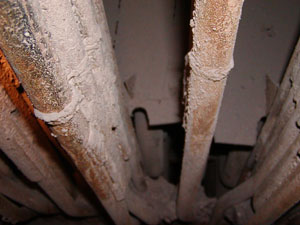 Figure 4
Floor seal showing no refractory
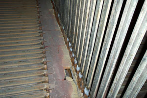 Figure 5
A cracked and broken gas baffle tile
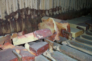 Figure 6
A gas baffle tile that has broken and fallen away
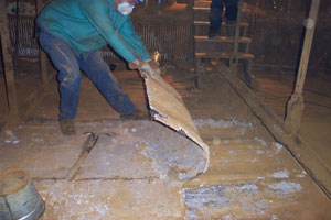 Figure 7
Expanded metal lath that’s not welded to tubes
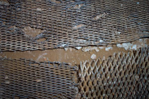 Figure 8
Close-up of two different sized laths used on roof
 Figure 9
Roof area with crack in refractory
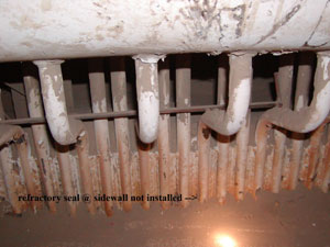 Figure 10
Junction of roof and side wall with no refractory seal
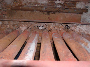 Figure 11
Downward view of heater seal
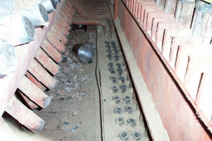 Figure 12
Super heater seal box with refractory in place
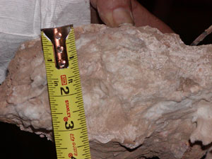 Figure 13
Top and middle layer of refractory seal
 Figure 14
Inspecting inside a penthouse