CHILL OUT!
Insulation systems for piping that operate at below-ambient temperatures present special challenges due the possibility of water vapor movement to the cold surface. If the operating temperature of the system is below the dew point of the ambient air, condensation will occur on the cold surface, creating a vapor pressure gradient through the system. This vapor pressure gradient serves as the driving force for water migration toward the cold surface. If these conditions remain for extended periods of time, a significant amount of liquid water can accumulate in the system. Below-ambient systems therefore require special attention to the design to maintain thermal performance.
The traditional approach has been to specify either a vapor-impermeable insulation material and/or a continuous vapor retarder on the warm side of the insulation to minimize vapor flow to the cold surface. A variety of facings and jacketing materials are available for use as vapor retarders. These products are designed for low water vapor permeance, with values as low as 0.02 perm achievable under laboratory conditions. Insulation materials with water vapor permeability values less than 0.005 perm per inch are available. In theory, these materials limit the rate of water vapor ingress to levels so low that the amount of condensed water is negligible. In practice, however, this approach requires that the vapor retarding system be continuous at all the joints, elbows, valves and fittings present in real installations. The degree of success therefore depends heavily on both the workmanship of the installers and degree of maintenance provided after installation. Even with careful installation of vapor retarders in conjunction with closed-cell insulation materials, a finite amount of water vapor enters the system and condenses to liquid water on the cold surface. Figure 1 shows a traditional installation with a vapor retarder jacket over a closed-cell insulation material where dripping, corrosion and mold growth are evident.
The "Self-Drying" Concept
An alternative approach utilizing wicking material to remove condensed water from the system has been in use since 1993. The approach accepts the fact that water vapor will eventually enter the system and condense on the cold surface, and provides a means to remove the condensed water while keeping the insulation material substantially dry.
A schematic of the "self-drying" concept on a below-ambient pipe is shown in cross section in Figure 2. A thin layer of hydrophilic wicking material is placed around the pipe. A layer of low-conductivity insulation material is located around the wick to limit conduction heat transfer to the pipe. A vapor retarder is typically placed on the exterior surface of the insulation to limit the rate of water vapor diffusion into the system. The wicking material is extended downward through a slot in the insulation layer, and the tail of the wick is left exposed to the ambient air to serve as an evaporator section.
Note that in the schematic the evaporator section of the wick is shown hanging straight down in a vertical position. In practice, this tail portion of the wick may be turned and adhered to the exterior of the vapor retarder. This is done for aesthetics and does not materially effect the operation of the system as long as the exposed area is sufficient to allow adequate evaporation. A commercial implementation of the concept showing an integral flap that covers the evaporator is shown in Figure 3.
In operation, any water vapor that condenses on the pipe surface is absorbed by the wicking material and transported via the combination of capillary forces and gravity through the slot and onto the exposed tail area, where it can evaporate to the ambient air.
Background
The "self-drying" concept of utilizing a wicking material to remove condensed water from a below-ambient pipe insulation system was conceived by Professor Vagn Korsgaard of the Department of Buildings and Energy, Technical University of Denmark. Original patent applications were filed in Denmark in 1990, and with the United States Patent Office in 1991. Korsgaard’s initial experiments with the concept are described in a technical paper presented at the 1993 ASHRAE Winter Meeting in Chicago. The paper described results of a one-year test of several "self-drying" pipe insulation designs installed on a 33 F chilled water loop. The results of the experiment demonstrated that "? it is possible to prevent moisture accumulation in cold pipe insulation by means of a concept utilizing the wicking action of a hydrophilic fabric to remove condensed moisture from the pipe surface through a slot in the insulation to the outer surface of the insulation from which it can evaporate into the ambient air."
Korsgaard published additional data in the Journal of Thermal Insulation in 1994, the Proceedings of the International Congress on Refrigeration in 1995 and in an ASTM Symposium on Insulation Materials in 1997.
Theory of Operation
To help understand the operation of the self-drying system, assume that wick and insulation are initially placed on dry pipe surface when the pipe temperature is in equilibrium with the ambient air. This is the situation that normally exists prior to system start-up. There is no condensation within the system, and the partial pressure of water vapor in the air trapped near the pipe surface is equal to the partial pressure of water vapor in the ambient air. For this equilibrium condition, there is no driving force and no water-vapor flow in the system.
During system startup, the temperature of the fluid in the pipe is reduced, and a temperature gradient is established across the insulation layer. This results in heat flow via conduction through the insulation toward the pipe surface. As long as the pipe surface temperature remains above the dew point of the trapped layer of air nearest the pipe surface, however, no condensation will occur. The vapor pressure near the pipe remains equal to the vapor pressure in the ambient air, and no water vapor flow occurs.
As the temperature of the fluid in the pipe is further lowered below the dew point of the air near the pipe surface, liquid water will begin to condense on the pipe surface. This reduces the vapor pressure of the layer of air immediately adjacent to the pipe to the saturation pressure, and a vapor pressure gradient is established. This vapor pressure gradient causes water vapor diffusion toward the pipe surface.
Initially, the condensed water will be absorbed into the hydrophilic wicking material. As the amount of absorbed water increases, the pores in the wick will fill, and capillary forces will induce movement of the liquid water toward dry areas of the wick. This capillary force, aided by gravity, will move liquid water through the slot to the evaporator region, where it can evaporate to the ambient air.
The advantage of this approach is that the wick material transports condensed water to the outside of the system. The wick keeps the hydrophobic insulation dry, allowing it to maintain its thermal performance.
Mathematical Modeling
The physical laws of thermodynamics, heat transfer and mass transfer that govern the performance of the self-drying concept are well known. A comprehensive mathematical modeling effort was undertaken to better understand the interactions of these physical laws as they apply to the self-drying concept1. The modeling study was also useful with product design and material selection. The study involved the solution of equations governing the transport of mass, energy and momentum in porous media. A significant, novel feature of the modeling work was that it incorporated transport processes in a hydrophilic wick fabric wrapped around the cold pipe and extending through the insulation.
Results of the modeling effort show a rapid initial weight gain followed by a plateau. This plateau represents a state of equilibrium whereby the amount of moisture condensing equals the amount of water being drained from the system. No further weight gain is experienced. This characteristic behavior is explained by the fact that the wick must be saturated before capillary action can begin.
The mathematical modeling effort demonstrated that the wicking concept is theoretically sound. The wicking material is capable of transporting condensed water outside the system, where it may be evaporated. The model also clearly demonstrated some key limitations of the wicking concept: 1) it is still necessary to employ a low permeance vapor retarder to limit the water vapor ingress to manageable levels, and 2) the model reinforced the requirement that the ambient conditions must provide opportunities for evaporation.
Laboratory Testing
While mathematical modeling is useful in understanding the theoretical performance of the pipe insulation system, an extensive experimental program was required to evaluate prototype product designs and to aid in developing installation techniques. Much of the testing was conducted in environmental chambers that allowed exposure of specimens to controlled temperature and humidity conditions.
Figure 4 shows a photograph of one of the chambers used. This particular chamber was valuable in that it could not only maintain steady conditions accurately, it could also be programmed to mimic varying temperature/humidity conditions.
The inside of this chamber is shown in Figure 5. For most of the tests run in the humidity chamber, 3-foot sections of insulation were installed on a 1-inch copper tubing 40 inches long. The exposed ends of the insulation sections were sealed by either dipping them in hot melt adhesive or by taping them shut. These assemblies were weighed and placed on a cold "finger" mounted in the humidity chamber. The temperature of the cold finger was maintained at the desired temperature, typically 35 F, by circulating cooled water-antifreeze solution through the system. This test configuration allowed periodic removal and weighing to determine weight gain due to water vapor ingress. The testing program involved more than 50 samples for periods ranging up to six months in duration.
Results of one series of experiments are given in Figure 6, which shows the cumulative weight gain for three specimens of ¾-inch NPS by 1.5-inch-thick fiberglass insulation sections fitted with wicking material. For this experiment, the humidity chamber was maintained at a constant 90 F and 80 percent relative humidity. This condition corresponds to a constant dew point temperature of 83 F and is considered severe from the standpoint of vapor drive (the ASHRAE 0.4 percent design dew point temperature for Miami, Florida, is 78 F).
As illustrated in the figure, there is a rapid weight gain within the first day of testing. Afterwards, the weight of the specimens remains relatively constant. This is consistent with results from the mathematical model in that an initial period of water accumulation must occur prior to saturation of the wick. During this initial transient period, there is no liquid water at the slot exit, leaving a relatively open path for water vapor to diffuse into the system. This "flaw" in the vapor retarder is narrow (generally less than 0.1 inches (2 mm) but runs the length of the pipe run.
When the wick becomes saturated, it begins to remove condensed water through the slot to the evaporator area. After this point, the flow rate of water vapor into the system equals the flow rate of liquid water out of the system, and a state of dynamic equilibrium is reached. This particular series of tests were continued for a period of two months without a further increase in weight. Subsequent disassembly and examination of the specimens reveals that liquid moisture is confined to the wick material; the insulation material stays dry.
These data indicate that the steady state weight gain during the initial transient period is roughly 15 grams per section of pipe. Experiments have shown that, if fully saturated with water, the wick material has the capability to hold about 36 grams of water per section of pipe. From this we conclude that 1) the weight gain measured is confined to the wick material and 2) the wick material, under continuous severe conditions, is less than 50 percent saturated.
Another interesting experiment was conducted with samples installed in the "slot-up" configuration to examine the consequence of possible misapplication of the product. Again, the conditions in the chamber were maintained at a constant 90 F/80 percent relative humidity with a 35 F operating temperature. Results are shown in Figure 7.
The result here is that the initial weight of approximately 32 grams per day does not level off, as before. This indicates that the water-vapor ingress into the system is greater than the rate of liquid water can be removed. After a period of six days, the accumulated weight of the sample had reached nearly 200 grams. At that point, the sample was rotated 180 degrees to the normal "slot down" position. The excess water drained and evaporated and the weight gain stabilized at a normal level of about 20 grams.
Another important series of laboratory experiments involved assessing the liquid water absorption characteristics of fiberglass insulation material relative to the wicking material. In general, fiberglass insulation is hydrophobic (sheds water) while the wicking material is hydrophilic (absorbs water). The self-drying concept relies on this distinction to keep the insulating material dry. To test this, samples of insulation were held horizontally with wicking material on top of the fiberglass. Water droplets placed on the surface of the wicking material spread smoothly. The fiberglass insulation below remained dry, and the presence of the insulation in contact with the wick did not affect the wicking pattern.
In follow-up experiments, samples of wick material were sandwiched vertically between pieces of hydrophobic fiberglass, leaving a 1-inch-wide lead of wicking material protruding from the bottom of the insulation. Capillary rise was measured by dipping the 1-inch lead in water (keeping the bottom faces of the insulation just above the water). Results are summarized as follows:
- The presence of the wool did not affect the capillary rise of the nylon wick.
- There was no detectable lateral water diffusion into the fiberglass insulation.
- These experiments confirmed the ability of the hydrophobic fiberglass insulation to remain dry even when in contact with a saturated hydrophilic wicking material.
Field Experience
Field trials of self-drying insulation began in April 2000. Initial installations were targeted to locations along the Gulf Coast and along the Eastern Seaboard. Table 1 (in Figure 8) provides a summary of some of the early installations.
These field trials yielded a wealth of experience with the self-drying insulation product and identified a number of points worth highlighting. Elbows, valves and fittings have been successfully insulated by wrapping with wicking material prior to installing insulation. Various installation details have been developed to accomplish this, but the key for installers is to utilize the wicking materials to transport condensed water to the lowest point in the system where it can be removed to the outside and evaporated.
Vertical runs are treated similarly, with the wicking material serving as the conduit to transport condensed water to a location where it can be removed from the system and evaporated.
The ability to install insulation on operating systems has proven to be a significant benefit. In some facilities, cooling systems are critical to operations, and shutting down to install insulation is not feasible. Since the wicking products are designed to remove water from the cold surface to the environment, surfaces do not need to be dry during installation. A number of hospitals and data processing centers have chosen to use wicking products to reinsulate existing cold lines while maintaining operations.
One of the earliest field trial installations was on the campus of the Old Dominion University in Norfolk, Virginia. Self-drying insulation was installed in a mechanical room at the Powhatan Apartments, a 23-year-old facility housing up to 384 upperclassmen. Existing pipe insulation was deteriorating in the mechanical rooms and also on pipe leading to individual apartments. The apartment project was selected for the demonstration because it offered easy access to pipe that needed new insulation and the pipe was exposed so it could be observed over time. Also, ambient conditions in the mechanical rooms would provide a good test with chilled pipe running through a hot and humid environment.
Fifteen months after the product was installed, the insulation was working well. Before the test, there were stain lines on the floors where condensation had dripped. The lines were removed and had not reappeared in the 15 months (spanning two summers) since installation. As the installation approached its third year in service, samples of the insulation were removed, examined and found to be dry and drip-free.
Conclusion
The "self-drying" concept invented by Professor Korsgaard has been in commercial operation in Europe since 1993. Researchers at Owens Corning’s Science and Technology Center began evaluations of the concept in 1998. The development effort involved extensive mathematical modeling, laboratory experimentation and field trials. As a result of these studies, Owens Corning introduced its product, based on the Korsgaard patent, in 2001.
1Karki, K.C. and Patankar, S.V., Innovative Research Inc., in partnership with M.K. Choudhary of Owens Corning, "Computational Model for Condensation in Fiberglass Insulation on a Cold Pipe," Report submitted to Owens Corning, July 1999.
The findings in this article were presented at NIA’s 49th Annual Convention, Tucson, Arizona, March 26, 2004.
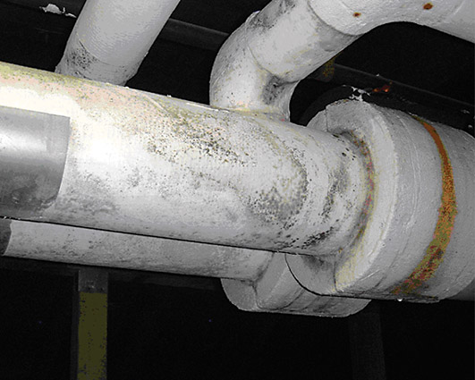 Figure 1
 Figure 2
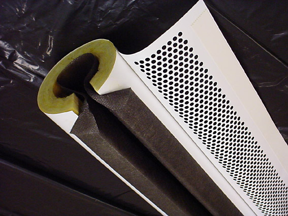 Figure 3
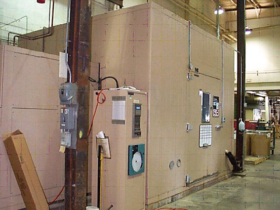 Figure 4
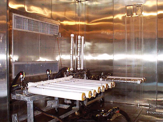 Figure 5
 Figure 6
 Figure 7
 Figure 8
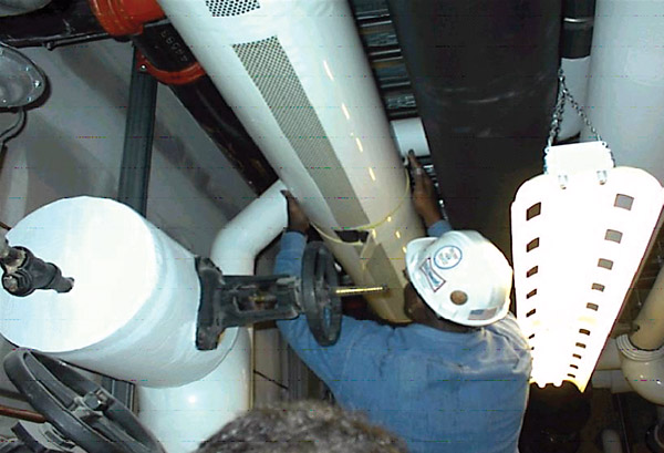 Figure 9