Complying with Fire Standards
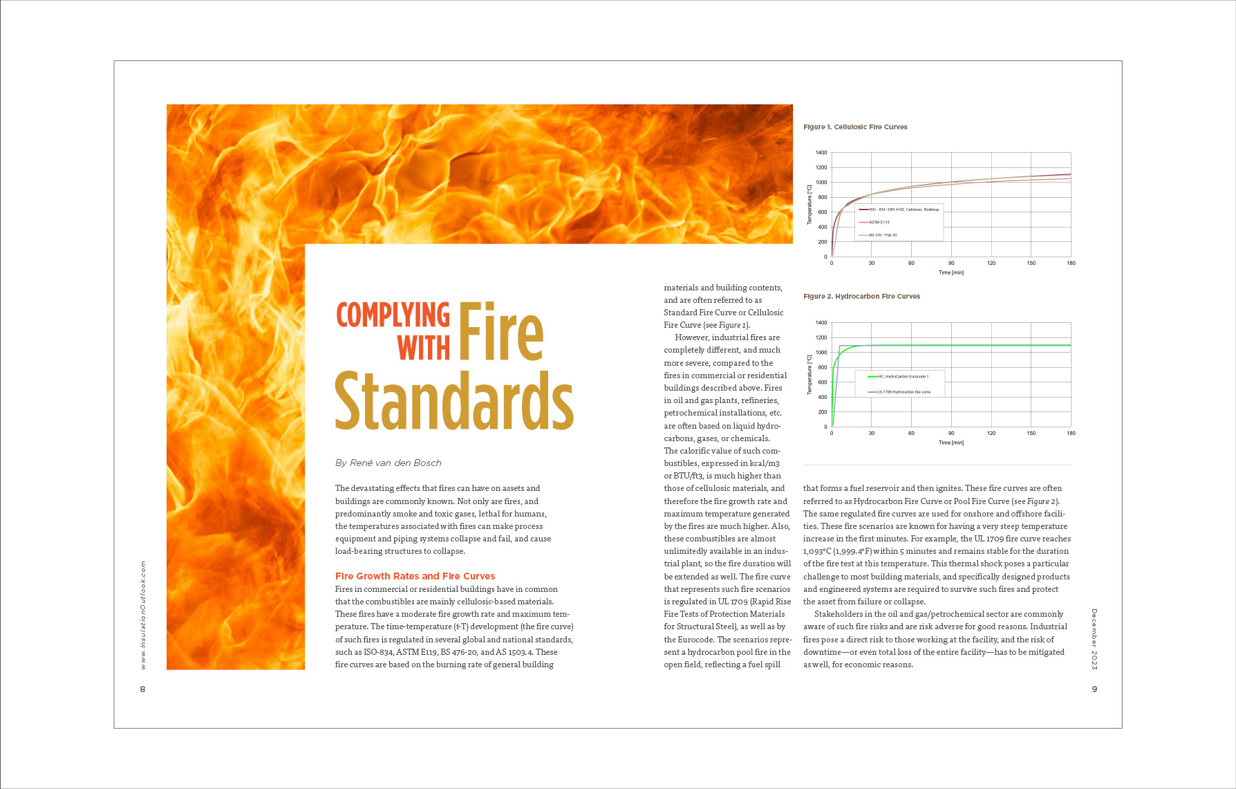
The devastating effects that fires can have on assets and buildings are commonly known. Not only are fires, and predominantly smoke and toxic gases, lethal for humans, the temperatures associated with fires can make process equipment and piping systems collapse and fail, and cause load-bearing structures to collapse.
Fire Growth Rates and Fire Curves
Fires in commercial or residential buildings have in common that the combustibles are mainly cellulosic-based materials. These fires have a moderate fire growth rate and maximum temperature. The time-temperature (t-T) development (the fire curve) of such fires is regulated in several global and national standards, such as ISO-834, ASTM E119, BS 476-20, and AS 1503.4. These fire curves are based on the burning rate of general building materials and building contents, and are often referred to as Standard Fire Curve or Cellulosic Fire Curve (see Figure 1).
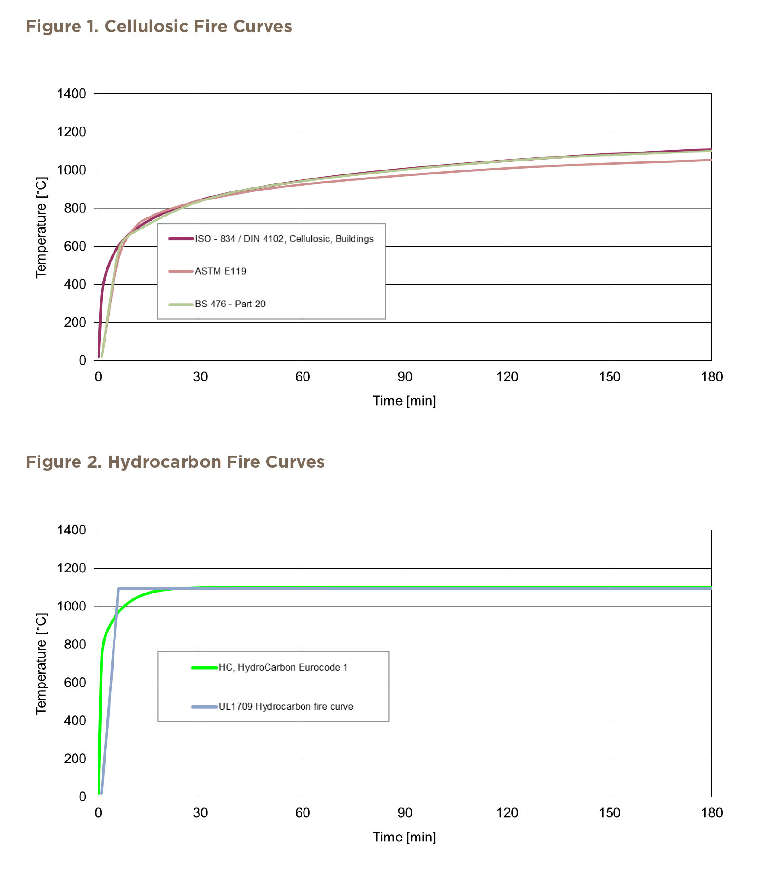
However, industrial fires are completely different, and much more severe, compared to the fires in commercial or residential buildings described above. Fires in oil and gas plants, refineries, petrochemical installations, etc. are often based on liquid hydrocarbons, gases, or chemicals. The calorific value of such combustibles, expressed in kcal/m3 or BTU/ft3, is much higher than those of cellulosic materials, and therefore the fire growth rate and maximum temperature generated by the fires are much higher. Also, these combustibles are almost unlimitedly available in an industrial plant, so the fire duration will be extended as well. The fire curve that represents such fire scenarios is regulated in UL 1709 (Rapid Rise Fire Tests of Protection Materials for Structural Steel), as well as by the Eurocode. The scenarios represent a hydrocarbon pool fire in the open field, reflecting a fuel spill that forms a fuel reservoir and then ignites. These fire curves are often referred to as Hydrocarbon Fire Curve or Pool Fire Curve (see Figure 2). The same regulated fire curves are used for onshore and offshore facilities. These fire scenarios are known for having a very steep temperature increase in the first minutes. For example, the UL 1709 fire curve reaches 1,093°C (1,999.4°F) within 5 minutes and remains stable for the duration of the fire test at this temperature. This thermal shock poses a particular challenge to most building materials, and specifically designed products and engineered systems are required to survive such fires and protect the asset from failure or collapse.
Stakeholders in the oil and gas/petrochemical sector are commonly aware of such fire risks and are risk adverse for good reasons. Industrial fires pose a direct risk to those working at the facility, and the risk of downtime—or even total loss of the entire facility—has to be mitigated as well, for economic reasons.
Why Protect Steel against Fire?
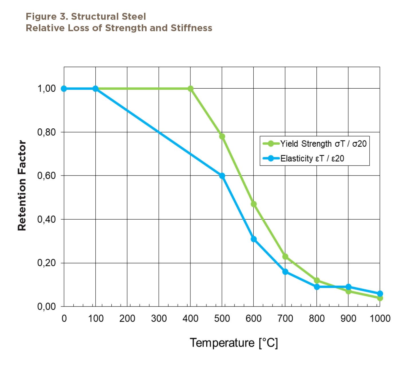
Even though steel is a non-combustible product, the loss of strength and stiffness when exposed to fire temperatures is significant. The Eurocode 3 provides retention values for both yield strength and elasticity, as a function of temperature, compared to the values at an ambient temperature of 20°C (168°F). Eurocode 3 retention values are very similar to those listed in ASTM A36.
A key takeaway from the graph in Figure 3 is that, for example, at a fire temperature of 600°C (1,112°F), the yield strength of steel is reduced by more than 50% of the yield strength at ambient temperature; and the elasticity is only 30% of the ambient value. Another example: At 1,000°C (1,832°F) fire temperature, both the yield strength and elasticity are reduced by more than 90% of the ambient value.
As stated previously, fire temperatures increase rapidly in the first few minutes of a fire—especially industrial fires, which reach nearly 1,100°C (2,012°F) within 5 minutes. Leaving steel members fully exposed to such fire temperatures raises a significant risk to deflection and structural collapse of those members early in the fire event.
For these reasons, industry practice is to protect critical steel members against fire risks by application of passive fire protection systems, which is regulated by industrial fire standards.
Governing Industrial Fire Standards
3.1. UL 1709—Rapid Rise Fire Tests of Protection Materials for Structural Steel
UL 1709 is the most commonly used fire standard, referenced in technical specifications by the oil majors, front-end engineering and design (FEED) engineers, and Engineering, Procurement and Contracting (EPCs). The current version of UL 1709 is the 6th edition, issued August 2022.
The basics of a compliance fire test to UL 1709-06 is that, when exposed to the UL 1709 fire curve, the average temperature of the thermocouples installed on the steel test specimen shall not exceed 538°C (1,000.4°F), and none of the thermocouples shall exceed a maximum recorded temperature of 649°C (1,200.2°F). (For further details on the test procedure, see the UL 1709-06 standard.)
On its web page, www.ul.com/resources/testing-and-certification-steelwork-fire-protection, UL acknowledges that the UL 1709 standard gets adopted increasingly. At the same time, non-UL test laboratories that are not accredited for UL 1709 fire testing seem to have different interpretations of the intended test methodology. On the referenced
web page, UL addresses some of the misinterpretations and provides clarity on some key principles of the fire test method, described in the following subsections.
3.1.1. Furnace Calibration
The current method for calibrating a furnace requires a single calibration column to be placed centrally within the furnace chamber. This is intended to reflect what will happen in the subsequent type of testing, thereby exposing the sample under test to the same thermal dose as the calibration column and ensuring a high level of consistency in evaluating the protection system from test to test.
It is not intended that more than one specimen be included in the furnace at the same time, as this will result in one or more sides of the columns being shielded from some of the heat within the furnace chamber, such that the intended time-temperature (t-T) and heat flux exposure to the specimen is not replicated. This practice is also likely to result in some columns being nearer to the walls of the furnace chamber, which also can result in a lower thermal dose on the protection system under evaluation.
3.1.2. Furnace Thermocouples
According to UL 1709, the furnace should be calibrated using eight thermocouples at a maximum distance of 102 millimeters from the exposed face of the specimen. That means eight thermocouples per column to ensure that the furnace temperature is controlled such that the test specimen is exposed to the intended t-T curve. These thermocouples also must be evenly distributed throughout the furnace to ensure an even evaluation of the thermal dose during the test. Uneven distribution of the thermocouples within the furnace chamber is likely to cause a heat gradient, causing uneven heating of the column(s).
3.1.3. Furnace Control
As with most furnace testing, there are variables due to the very nature of the equipment being used. The standard provides guidance on the level of acceptable variation, in particular with the temperature within the furnace chamber. The intention is that the tolerances are there as guidance to compensate for fluctuation and not to be used, in continuous operation. In the ideal test, the tolerances would not be used, and the furnace would operate within the mean values. To operate the furnace such that it runs toward the lower or upper tolerances will give a lack of consistency between tests as well as between protective systems being evaluated. This is of particular concern when the lower range of tolerance is targeted. This practice should not be followed, and test data generated via a test operated at the lower end of the tolerances throughout the test should be treated cautiously, with the understanding that the protective system tested may not perform as other products evaluated to the prescribed fire curve.
3.1.4. Specimen Thermocouples
UL 1709 is clear on the number of thermocouples to be used on each specimen. There are a number of reasons why this should be followed, not least of which is to provide a consistent approach to the evaluation of the protective system. In some cases, we are aware that less than the number of required thermocouples are used on the test specimen(s). While this is not in accordance with the standard requirements, the greater concern is that there may be a part of the protective system that gets overlooked because of the reduced number of specimen thermocouples. Given that this test is only evaluated to temperature limits, rather than the structural limits, it is imperative that all instruments are installed as required so that a representative sampling across the full test specimen is captured.
Chapter 5 of the standard is clear that 20 specimen thermocouples should be used per column. As with the furnace control matter discussed in the previous section, data produced using fewer than 20 thermocouples per column should be treated with caution and considered not compliant with the requirements of the test standard.
3.1.5. Protective System
In all fire tests, the tested system should be representative of what will be used in the final installation on site. Any changes made to what was tested and certified likely will impact performance. This means it is critical that the details of the tested system are recorded
accurately and the system is then installed in practice as required in the certification documentation. If these details are not followed, there may be a loss of fire performance and a threat to life safety.
For instance, in cases where a stainless steel wrap is added to columns for the test, even though it does not have a high thermal insulation value, the addition of the casing will add thermal protection to the steel column. It will do this by creating an air gap that insulates the column and by stopping the convection of hot gases in the furnace, which otherwise might have penetrated the protective system. This is just one example of how a small
element of the protective system—one that may appear to add little or no thermal resistance—can be critical to the system’s overall fire performance, proven by way of
fire testing. Therefore, the full configuration of the protective system, as tested, shall be installed on site as well to help ensure the required fire safety levels are provided.
3.1.6. Durability
Often, the protective products tested and certified to UL 1709 are placed in harsh environments in practice. For this reason, the standard mandates durability testing that simulates these harsh environments be performed on all protection systems intended to be certified to UL 1709. The durability testing is conducted to UL 2431, the Standard for Safety for Durability of Fire Resistive Coatings and Materials, and the protection systems must comply with all requirements for Material Classification Category I-A: Outdoor, Heavy Industrial, as prescribed in the standard. The individual listing on UL’s Product iQTM database will indicate the protection system’s compliance with these durability testing requirements.
3.1.7. Official Material Sampling by UL for Fire Testing Purposes
In addition to the clarifications above, provided by UL, UL also insists and ensures that the products that will be used for the actual UL 1709 fire test(s) are being independently selected by a UL representative at the vendor’s factory. This aims to ensure that the tested product quality and specifications are representative for the actual products that are supplied and installed on site.
Summary
Fire protection systems are critical for protecting life and assets. They must be designed and tested for the specific application, and installed per the resulting specifications, to ensure performance meets expectations. For passive fire protection systems to function properly in a fire event, it is critical to follow all details of the governing test standards. Deviating from the test standard, intentional or not, may lead to premature failure and loss of assets, and may expose users to unnecessary safety risks.
René van den Bosch is the Director, Global Passive Fire Protection at Armacell. He is a structural engineer with 30 years of experience in the field of passive fire protection and is a voting member of the ASTM C16.23 and ASTM E05.11 technical committees. He served as a voting member of the NFPA502 technical committee for 14 years and contributed to several international fire safety research projects in the civil construction industry.