Corrosion in Cold Insulated Systems
To successfully prevent pipe corrosion on cold insulated lines and equipment, it’s important to properly match the materials used to the conditions of the application. When a cold insulation system breaks down and fails, it usually means that the insulation must be replaced, and if the replacement is left unabated, the pipe or equipment may need to be replaced.
Hot systems may have isolated areas with wet insulation requiring remedial patch work of insulation for corrosion control. Cold insulation systems must deal with water vapor, not just water. This condition separates the hot insulated systems from the cold insulated systems. Before we discuss corrosion, we will first look at the causes of failure to a cold insulation system.
First, the vapor retarder as specified may have an unsuitable permeance rating for the application conditions. For very cold systems with marginal insulation, the vapor pressure can exceed the capability of the vapor retarder. When insulation systems constantly sweat on the outer surface, it’s a sign that the insulation finish surface temperature is below the dew point. This is when the installed insulation vapor retarder is really being tested.
Water Vapor Issues
Water vapor in the air will move from areas of high vapor pressure toward areas of low vapor pressure. The vapor movement rate depends on the permeance of the material through which the vapor transmission takes place. This material may be a mastic system, a membrane finish, the insulation itself or a composite of these materials.
The driving force of this water vapor pressure is dependent on the variation in the conditions outside the insulation and on the condition at the cold substrate.
Lets look at a hypothetical condition. The surface of the insulation system is exposed to 90 degrees fahrenheit (32 degrees celsius) and 80 percent relative humidity. According to the Dew Point Table, the dew point is 83 degrees (28C). With an insulation system surface temperature of 60 degrees (16C), using the same RH the dew point temperature is 54 degrees (12C) at this surface. This calculation only applies to the movement of water vapor across the vapor retarder and not from the ambient environment to the pipe surface. We have a condensate (sweating) problem (surface temperature below the ambient dewpoint) and we may also have a vapor transmission problem. The water vapor pressure, in inches Hg. for a dew point of 83 degrees (28C) is equal to 1.14, and with an insulation dew point of 54 degrees (12C), the water vapor pressure at the surface is 0.422. The difference of the two water vapor pressures is equal to 0.718 inches Hg.
From Fick’s Law on vapor transmission: W equals M A T (Delta P). W equals weight of water vapor in grains (7,000 grains equals 1 pound of water). M equals water vapor permeance through the vapor retarder in grains/feet per square hour inches. Hg (perms).
For this exercise we will say that the vapor retarder has been tested in accordance with ASTM E96 and is rated at 0.10 perms:
- A is equal to Area that transfer occurs (square feet.)
- T is equal to Time (hours)
- Delta P is equal to Vapor pressure difference (inches of mercury)
- W is equal to 0.10 x 1 x 1 (1.14 – 0.422)
- W is equal to .0718 grains of water per hour per square foot.
This may not seem like much water, but look at it over a period of time and a larger area. Over a period of one year ( 8,760 hours) and a pipe system with 45 square feet (an approximately 8 inch line, 50 feet long).
- W (total) is equal to .0718 x 45 x 8,760
- W (total) is equal to 28,304 grains of water
- W (pounds) is equal to 28,304/ 7,000 equals 4 pounds of water per year.
Again, this is a hypothetical study and it’s unlikely that the environmental conditions would remain that severe for 12 continuous months. However, it does point out that even with a perfectly installed insulation system, water vapor can permiate into the insulation. To reduce the water vapor permiation by 1/5th the amount under the same conditions, install a vapor retarder with a perm rating of M equals 0.10 /5 equals 0.02.
The above condition should never occur if proper conditions are specified up front. With the previously mentioned environmental condition, the insulation thickness must be selected to achieve the acceptable surface dew point (condensation control). The 3E Plus® Program will do this for you. As mentioned in a previous article in Insulation Outlook, select a finish that has an emissivity of 0.8 or higher wherever possible. The insulation surface dew point should improve, and possibly reduce the insulation thickness.
Insulation’s Role
We have only addressed the virtues of the vapor retarder finish. The insulation can also play a roll in reducing the water vapor transmission to the substrate. Cellular glass insulation has a permeability rating of 0.00 permeance per inch and should eliminate the possibility of vapor moisture migration to the substrate (or at least reduce the water vapor transmission). Foam insulations have permeability ratings that range from 0.5 to 7 permeance per inch, while fibrous insulation is in the area of 100 permeance per inch. The specifier should consider the benefits of the insulation permeability when designing an insulation system for cold service.
However, all insulation systems have joints that might not be completely sealed, or contraction or vibration of the system can open the joints. Hairline cracks are common in all types of insulation systems caused by handling or securing the insulation to the pipe or equipment. In this writer’s opinion, a good vapor retarder coupled with a low permeability insulation means a cold temperature system will successfully perform for many years. By neglecting to specify the proper vapor retarder and insulation, the entire insulation system will likely have a shortened life. The initial cost of a good vapor retarder and insulation and labor to install it is minimal compared to the total cost of an insulation system that fails and needs to be replaced.
Using the same conditions as indicated in the previous study, an insulation is rated at 4 permeance per inch. There is an equivalent of 3 square feet of gouges and tears in the vapor retarder. Assuming 1-inch thick insulation and using the above formula, we have:
- W is equal to 4 x 3 x 8,760 x 0.718
- W is equal to 75,476 grains of water
- W (pounds) is equal to 75,476/7,000 equals 10.8 pounds of water over a one-year period from a 3-square foot opening.
Insulation resistance to vapor moisture does improve the battle against water vapor migration, but the vapor retarder should be the principle deterrent.
Most building structures have one great advantage over cold operating pipe and equipment: The buildings can breath. The vapor moisture that passes through the vapor retarder, in small quantities can pass through the insulation, the building wall and dissipate into the cold outdoors. Under normal conditions a pre-engineered building with insulated roof and walls may drive 1 pound of water in a week over a 5,000-square-foot area through the vapor retarder under certain weather conditions. This is considered acceptable.
For cold pipe and equipment, the vapor moisture has nowhere to go but accumulate at the substrate or within the insulation, and if the moisture reaches a temperature of 32 degrees (0C), it becomes ice. This ice will expand and destroy all types and forms of insulation. It will continue to build until the insulation system is completely destroyed all the way to the outside finish.
Actually, the moisture will seek out someplace to go. Most operating systems are periodically shut down for maintenance. The ice melts and the moisture travels the length of the pipe or equipment between the substrate and the insulation. In short time, the entire insulated system is destroyed.
Corrosion of the substrate is also a major concern. Austenitic stainless steel pipe and equipment is unlikely to develop stress corrosion cracking (SCC), provided the metal’s temperature is kept cool. This condition generally requires a service temperature above 120 degrees (49C) and general corrosion is very unlikely unless unusual contaminants are in the moisture. However, in cycling service or if the system is periodically cleaned using hot solutions, water or steam, SCC can become an issue. Given the rarity of this, carbon steel pipe and equipment is our major concern.
Ammonia Issues in Cold Storage
The ammonia process is the refrigerant of choice for food cold storage and processing facilities. The failure of insulated ammonia systems is more common than one would expect. The operating temperature of these ammonia systems varies between minus 50 degrees and 50 degrees. There is zero tolerance for mistakes in installation of these processes. The American Society of Heating, Refrigerating and Air-Conditioning Engineers (ASHRAE) Handbook on Refrigeration has dedicated an entire chapter (Chapter 3) to this subject.
ASHRAE states that ammonia is considered toxic at low concentration levels. Ammonia can burn and even explode when exposed to open flame. It can be hazardous to personnel and destroy food products. ASHRAE states that "rusting pipes and vessels in older systems containing ammonia can create a safety hazard."
In one situation, an ammonia line failed as the result of external corrosion under insulation. The facility was in operation for a short time. The corrosion took place on a 2-inch carbon steel pipe. Inspection of the failure indicated that the point of vapor moisture entry was several feet from where the pipe actually failed. The insulation system on the pipe appeared to be functioning properly. However, there was a break in the insulation as the pipe passed through an interior fire wall. The insulation and sealing system that butted against the fire wall was inadequate. It appeared that there wasn’t compensation for expansion and contraction of the adjacent long pipe run. The only tell-tale sign was a streak of discolored moisture running down the wall, below the pipe. (Photo 1 shows a piece of the pipe cross section that was next to where the failure took place.) It was a schedule 80 pipe with a 1/4-inch wall thickness. The inside diameter of the pipe remained the same. Maximum corrosion took place at the bottom of the horizontal pipe. This is to be expected, since this is where the moisture collected.
It seems like a simple task to develop a positive method to seal the insulation system at these points but it’s these type locations that usually create serious consequences. For those who believe that any pipe escutcheon (flange) is the answer, take a close look at the design. It may only be for piping that doesn’t move. (Photo 2 indicates a two-piece escutcheon developed by a leading PVC manufacturer.) This design can be sealed to the insulation vapor retarder and the wall. The PVC has the flexibility to compensate for expansion and contraction without breaking the seal at the wall. The escutcheon is molded PVC, 50 mils thick with a permeance rating of less than 0.03, in addition to the vapor retarder under the PVC. There may be other designs or simple methods to address this. However, the problem still exists.
Not all external corrosion failures to pipe and equipment occur directly on an insulated system. The insulator will terminate the system where there’s an obstruction, such as at a flange or valve. This is standard practice. However, the space between the face of the flange and the terminated insulation may be minimal. Perhaps the bolts may even extend into the insulation butt. The insulator will attempt to seal the exposed insulation with a vapor retarder mastic system. It’s impossible to reach into the tight quarters with a trowel or brush to assure complete coverage (see photo 3, on page 10 and 11). This problem could be eliminated simply by cutting the insulation back a few inches from the obstruction.
The oxygen-hungry contaminants will corrode away the pipe near the point of insulation termination. The insulation acts as a pond for the water formed from melting ice and is in a position to attract the necessary oxygen. This is why many corrosion failures on pipe will be near the termination of insulation. It’s infrequent to find corrosion under ice, but with moisture and oxygen there’s corrosion. That’s why cycling systems that freeze and thaw are at greatest risk with corrosion
These insulation terminations, especially on pipe, should be treated as vapor stops. It matters little whether the insulation has a 0 permeability or 100 permeability. The vapor moisture will find its way between the insulation and pipe unless there’s a vapor stop.
Vapor Stops
Many specifiers of cold insulation systems have adopted vapor stops at insulation terminations such as at flanges, valves and at directly attached pipe supports, guides and at anchors. Virtually anywhere where the continuity of the vapor retarder is broken the use of a vapor stop is mandatory. Vapor stops are also mentioned in the ASHRAE Refrigeration Handbook, Chapter 32. Some suggest going one step further and installing vapor stops periodically in straight runs of insulation, and at ells.
A vapor stop is a generous and complete coating of non-setting sealer over the entire butt end of exposed insulation, and onto the pipe and outside diameter of the insulation with a 1-inch lap. If the insulation has a factory applied vapor retarder finish, then overlap the finish and cover with a butt strip. Should the insulation vapor retarder finish be field applied, then apply the vapor stop first and then apply vapor retarder finish over the butt joint. Mastic manufacturers provide a non-hardening butyl sealant that remains flexible to minus 100 degrees (minus 73C). There also may be other non-hardening sealants that work just as well at specified temperatures.
When specifications indicate that all joints be staggered, including the circumferential joints, then cut the insulation flush wherever a vapor stop is desired. This is no different than installing pipe insulation with a factory applied vapor retarder finish.
Where double layer insulation is specified with all joints staggered, provide a 6-inch offset at the circumferential joints, and coat the 6-inch inner face and the butt joint with the vapor retarder mastic. Typically only the outer layer of insulation joints are sealed on multi-layer applications. The vapor stop is an exception.
On cold systems below minus 100 degrees (minus 73C) some specifiers apply a vapor retarder system between an inner and outer layer of insulation. In this case the vapor stop would apply to the outer layer of insulation at the butt joints. At these temperatures, valves, flanges and all obstructions would be completely insulated and sealed. With the non-setting sealer exposed to temperatures below minus 100 degrees (minus 73C) at the insulation terminations, the vapor stop would fail anyway.
Some insulation fabricators provide ship lap and/or tongue-in-groove circumferential and longitudinal joints on pipe, ell and tee insulation. If the insulation you specify is available with this feature, then it should be considered in the specification for systems operating below 0 degrees F (see photos 4 through 8). This joint treatment will work well with the intermediate and termination vapor stops. Ship lap joints will reduce the need for double layered insulation and contraction joints to much lower temperatures, thus preventing thermal short circuits at a reduced cost. The overall advantages will be dependent upon the type of insulation specified.
Unfortunately, most cold operating pipe and equipment failures aren’t obvious. The insulation system that covers them makes walk-through inspections of little value. Cold storage facilities generally have their compressors and associated piping on the roof. The industrial plants have their cold facilities outdoors. The roof or ground may be wet from weather conditions or it may be wet from a failed insulation system on a refrigeration system.
Inspections by maintenance and/or the building superintendent must be thorough and frequent. The inspections must include the insulation, even if it requires installing inspection ports or removing a section of the insulation where corrosion of the substrate is suspect. The walk-through inspection won’t prevent a disaster.
Summary
The following is a summary of why we insulate cold operating systems and how we can best prevent a failure from occurring.
1. Cold piping and equipment are insulated for some of the following reasons
- to minimize heat gain and improve efficiency, which reduces energy consumption and operating costs
- to control surface condensation
- to reduce noise
- to protect personnel and prevent unsafe ice formations
2. Measures to prevent corrosion under insulation or adjacent to the insulation
- Before installing any insulation, all pipe and equipment surfaces must be dry and clean from contaminants and rust.
- Apply a suitable paint system to carbon steel pipe and equipment. A primer will not prevent corrosion. It must be a submergible type paint system, as indicated in the NACE Standard RPO198-98 Item No. 21084 or ASHRAE Refrigeration Handbook, Chapter 32, Table 1.
- The coating should also be applied to any exposed area of pipe, including valves and flanges.
3. Correct insulation system for the process and the environment
- The insulation must be thermally efficient and of proper thickness to prevent condensation on the surface, except for very unusual high humidity conditions.
- The specified vapor retarder must be the type to withstand anticipated mechanical abuse. Otherwise a protective jacketing is required.
- The specified vapor retarder should have a permeability rating consistent with the environmental conditions and the operating temperature of the system. For cold systems, this must be at least 0.05 perms and for systems operating below 32 degrees fahrenheit, a permeance of less than 0.02 perms should be considered.
The specified vapor retarder should be user friendly. The insulation contractor will usually install what is specified. If a vapor retarder sheet material is easy to install on pipe insulation, a provision must be made for irregular shapes such as ells, valves and flange covers. A vapor retarder material that’s difficult to install may not be installed correctly. Vapor retarder mastic systems must be a uniform wet or dry thickness per the manufacturer’s specification. Membrane sheet and strip material is dependent upon the complete sealing of the overlapping seams during the life of the insulation system. With the correct insulation specifications, the life of the insulation system and corrosion free pipe and equipment is ultimately in the insulator’s hands. Let’s give them all the help we can.
4. Frequent inspections
- The maintenance supervisor and superintendent should be just as familiar with the insulation specifications as the pipe and equipment specifications. The general contractor, maintenance contractor or insulation contractor should provide a copy of the insulation specifications.
- Inspections should be scheduled weekly.
- The inspections should be thorough. Inspection under the insulation on a monthly basis should be considered as a mandatory requirement.
- Inspection should be performed on a daily basis on any re-insulation work. This will confirm that the specifications are followed, that vapor stops are applied properly and that the substrate surface is rust and corrosion free. The contractor will appreciate such close scrutiny, especially if litigation can be avoided through prevention of a massive failure.
- Finally, look for failure in the obvious places. Any discontinuity in the insulation finish (vapor retarder) such as a wall or tee (branch pipe), ell or flange, is a candidate for failure.
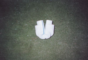 Figure 1
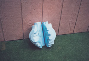 Figure 2
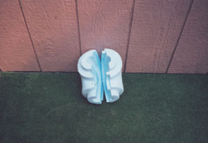 Figure 3
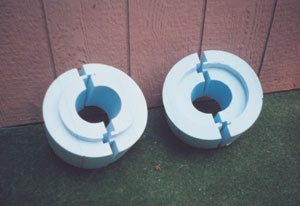 Figure 4
 Figure 5
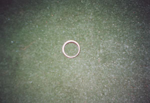 Figure 6
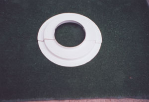 Figure 7
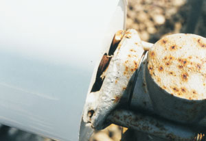 Figure 8