Design Considerations for Airports and Commercial Building Chilled Water Systems
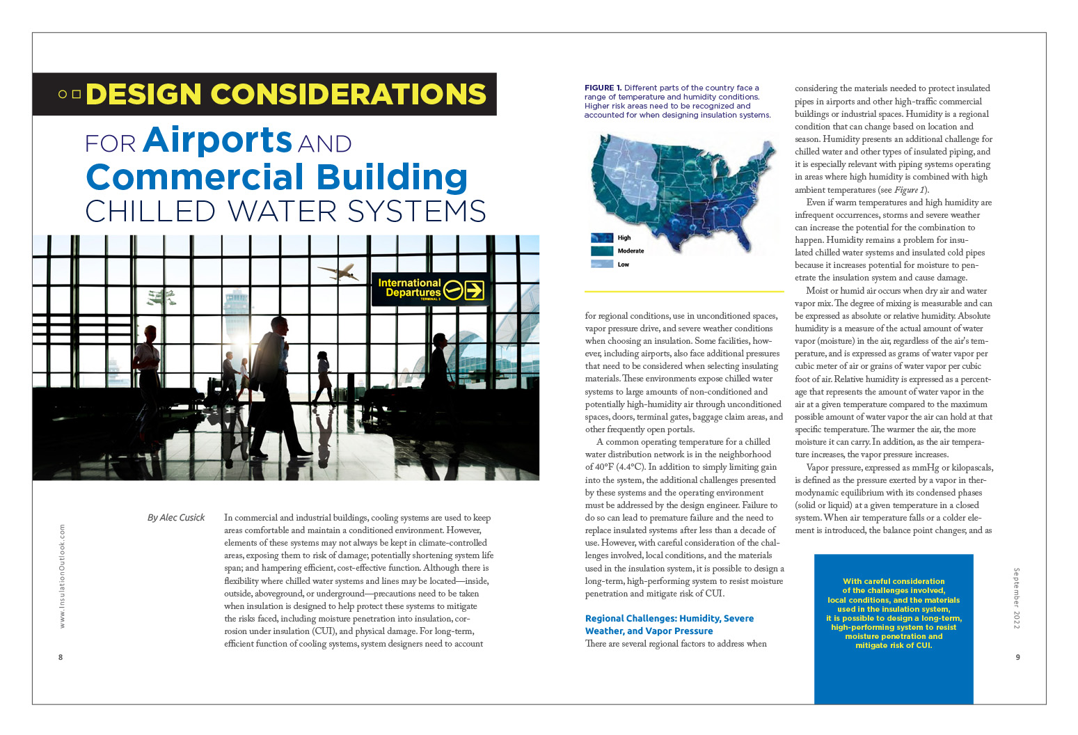
In commercial and industrial buildings, cooling systems are used to keep areas comfortable and maintain a conditioned environment. However, elements of these systems may not always be kept in climate-controlled areas, exposing them to risk of damage; potentially shortening system life span; and hampering efficient, cost-effective function. Although there is flexibility where chilled water systems and lines may be located—inside, outside, aboveground, or underground—precautions need to be taken when insulation is designed to help protect these systems to mitigate the risks faced, including moisture penetration into insulation, corrosion under insulation (CUI), and physical damage. For long-term, efficient function of cooling systems, system designers need to account for regional conditions, use in unconditioned spaces, vapor pressure drive, and severe weather conditions when choosing an insulation. Some facilities, however, including airports, also face additional pressures that need to be considered when selecting insulating materials. These environments expose chilled water systems to large amounts of non-conditioned and potentially high-humidity air through unconditioned spaces, doors, terminal gates, baggage claim areas, and other frequently open portals.
A common operating temperature for a chilled water distribution network is in the neighborhood of 40°F (4.4°C). In addition to simply limiting gain into the system, the additional challenges presented by these systems and the operating environment must be addressed by the design engineer. Failure to do so can lead to premature failure and the need to replace insulated systems after less than a decade of use. However, with careful consideration of the challenges involved, local conditions, and the materials used in the insulation system, it is possible to design a long-term, high-performing system to resist moisture penetration and mitigate risk of CUI.
Regional Challenges: Humidity, Severe Weather, and Vapor Pressure
There are several regional factors to address when considering the materials needed to protect insulated pipes in airports and other high-traffic commercial buildings or industrial spaces. Humidity is a regional condition that can change based on location and season. Humidity presents an additional challenge for chilled water and other types of insulated piping, and it is especially relevant with piping systems operating in areas where high humidity is combined with high ambient temperatures (see Figure 1).
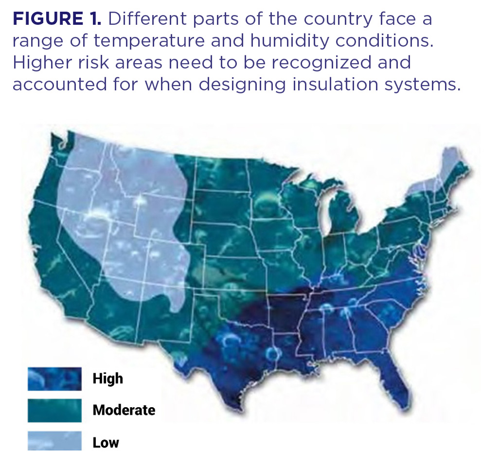
Even if warm temperatures and high humidity are infrequent occurrences, storms and severe weather can increase the potential for the combination to happen. Humidity remains a problem for insulated chilled water systems and insulated cold pipes because it increases potential for moisture to penetrate the insulation system and cause damage.
Moist or humid air occurs when dry air and water vapor mix. The degree of mixing is measurable and can be expressed as absolute or relative humidity. Absolute humidity is a measure of the actual amount of water vapor (moisture) in the air, regardless of the air’s temperature, and is expressed as grams of water vapor per cubic meter of air or grains of water vapor per cubic foot of air. Relative humidity is expressed as a percentage that represents the amount of water vapor in the air at a given temperature compared to the maximum possible amount of water vapor the air can hold at that specific temperature. The warmer the air, the more moisture it can carry. In addition, as the air temperature increases, the vapor pressure increases.
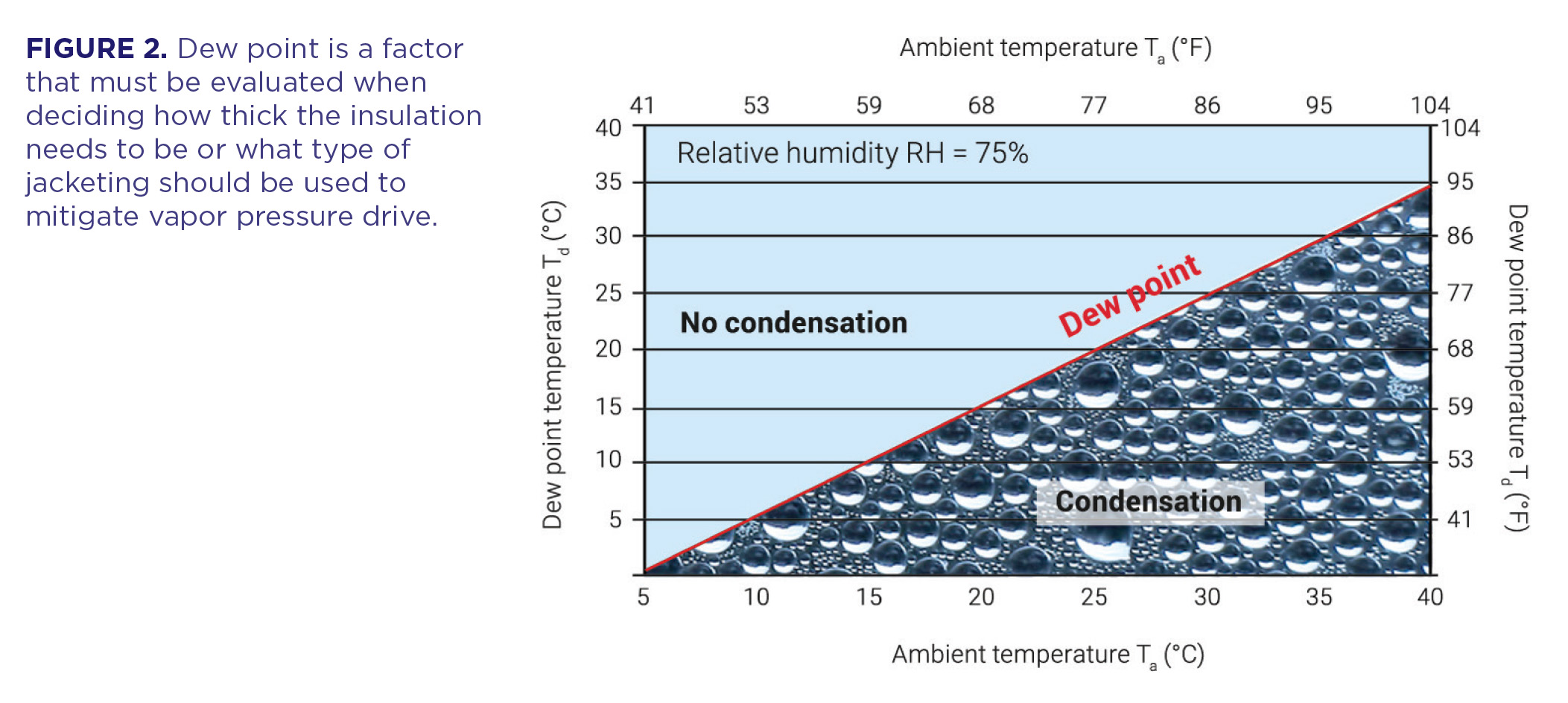
Vapor pressure, expressed as mmHg or kilopascals, is defined as the pressure exerted by a vapor in thermodynamic equilibrium with its condensed phases (solid or liquid) at a given temperature in a closed system. When air temperature falls or a colder element is introduced, the balance point changes; and as a result, water vapor will condense as dew until a new equilibrium point is reached.
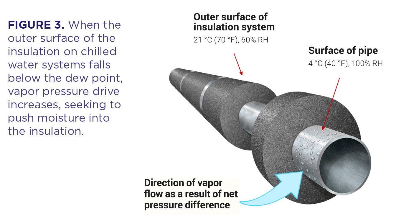
The dew point is the temperature where condensation starts (Figure 2). Differences in vapor pressure pose a risk to permeable insulation materials when used on below-ambient temperature systems. This is because the vapor pressure is higher on the outside of the insulation system than it is at the interface between the insulation and the pipe. As stated in the second law of thermodynamics, when isolated systems are allowed to interact, they will seek equilibrium. The result is a vapor pressure drive that tries to force moisture into the insulation system toward the pipe/insulation interface (Figure 3). Given the low temperature of insulated chilled water pipes, vapor pressure pushing moisture toward the surface of pipes is present in most climates. As the imbalance between the cold temperature of a chilled water pipe and the warm temperature of ambient air increases, the vapor pressure drive into the insulation and toward the pipe is heightened.
Although the drive from vapor pressure and moisture seeking ingress toward chilled piping is always a concern for chilled water systems, the risk can be higher for systems using permeable insulation. Permeable insulation relies on an external vapor retarder jacketing to help keep moisture out of the system. This leaves the systems open to risk of moisture penetration if the outside vapor barrier is insufficient or damaged. In regions with strong vapor pressure drive resulting from regular hot and humid conditions, permeable insulation can rapidly degrade once moisture penetration occurs. It is possible that insulation on chilled water lines may be destroyed in as little as a single cooling season if conditions are severe.
Additionally, insulation systems for chilled water lines need to be designed for more than just average conditions and humidity. Strong weather, like summer storms, can create severe conditions capable of overwhelming an insulation system with extreme humidity. The insulation thickness may not be enough to adequately protect pipes from the added vapor pressure drive if the system was designed and installed based on average conditions.
Similarly, insulation systems can be overwhelmed when the cooling system is started before the building is fully complete. While this practice is often followed, it exposes the insulation system to conditions it was not designed to handle and creates additional risk for condensation and for moisture to penetrate the insulation. Permeable insulations on chilled water lines often start to fail when originally put in operation while the building is still “open.” This is because permeable materials are particularly susceptible to ambient conditions. Exposing insulation designed for operation in conditioned spaces to areas in the building that are unconditioned also can strain system function and expose it to additional risk. Again, in this case, the system is being used under conditions for which it was not designed. One way to mitigate some of the risks is choosing an impermeable insulation material to use on chilled water lines. When chilled water lines run outside either aboveground or underground, additional consideration needs to be made to protect lines from elements including UV rays, vermin, weather, flooding, etc. If pipes are going to be direct buried, it is necessary to ensure the insulation has sufficient compressive strength to accommodate the soil backfill and any additional surface loads.
A test commonly used to check for vapor transmission through materials is ASTM E96 Gravimetric Determination of Water Vapor Transmission Rate of Materials.1 The test is run as either a Desiccant Method or Water Method. This relates to whether the material being examined faces 0% and 50% relative humidity on opposing sides, or if the material experiences 50% and 100% on opposite sides. When assessing materials for use in chilled water insulation, it may be more accurate to use results from the Water Method.
Planning Insulation Thickness and Temperature
As discussed, permeable insulation systems have a high probability of premature failure in the presence of high-humidity environments where there is a strong vapor pressure drive. This probability of failure becomes a certainty if the vapor barrier on the permeable insulation system is damaged. There are ways to help long-term function of the insulation system on chilled water piping. First, given that the greatest risk factor for chilled water lines comes from vapor pressure drive, the first step to designing a successful chilled water insulation system is to specify the insulation thickness to be great enough for the temperature of the outer surface of the insulation system to remain above the dew point as much as possible. Keep in mind that systems located in unconditioned spaces likely will be exposed to conditions that allow the formation of condensation. The goal in these cases is to minimize the potential for condensation while considering the economics and possible physical limitations (available space, etc.) of the system.
Keeping the surface of the insulation system above the dew point reduces the potential for the formation of a vapor drive outside of the system and the tendency for moisture to be forced into the insulation. Additionally, selecting an impermeable insulation material, like cellular glass insulation, also can help mitigate moisture penetration. The insulation material selected needs to be combined with the correct accessories, including joint sealant, jacketing, or mastic (Figure 4).
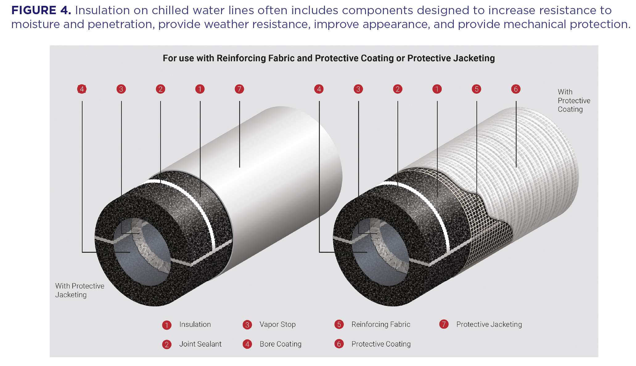
The joint sealant is used to seal the longitudinal and circumferential joints between the sections of insulation. Joint sealant also is used to seal any penetrations or protrusions in the system, and it can be used to seal metal jacketing laps. It is important to note that joint sealant or mastic is not intended to make up for poor-fitting or incorrectly installed insulation. Pipe insulation should be supplied from the fabricator and installed in such a way that the insulation fits tightly to the pipe without excessive gaps or joints wider than 1.6 mm (1/16 inch). Insulation jacketing often is used to provide an additional protection to the insulation—for example, helping protect against vapor drive and weather. It often will provide an aesthetically acceptable finish in areas where the system is visible to the public. Insulation jacketing also can be aluminum or stainless steel, providing excellent protection against mechanical damage as well as outstanding UV and weather resistance if needed. Mastics can be used as a protective coating on their own or may be combined with a tougher, outer-protective layer.
The type of outer layer used is typically influenced by the conditions and risk factors the insulated pipes will face. Another factor to consider when selecting insulating materials is the emissivity of the outer layer. Materials with a low emissivity, like unpainted metal jacketing, tend to have lower heat gains, while materials with higher emissivity are more responsive to gaining heat through radiation. High-emissivity materials include painted metal, all-service jacketing (ASJ), and PVC.
As an example of what jacketing emissivity can mean for insulation temperature, consider an 8‑inch NPS chilled water pipe operating at 40°F (4.4°C) and insulated with 76mm (3 inch) thick type X insulation. The ambient conditions are zero wind, an ambient air temperature of 90°F (32.2°C), and 80% relative humidity. This means the insulation system is faced with a dew point of 83°F (28.3°C). If low-emissivity jacketing like aluminum jacketing (emissivity [ε] = 0.04) is used, then the surface temperature of the jacketed insulation will be approximately 81.9°F (27.72°C) while the system is in operation. The surface of the insulation system will fall below the dew point in this case, which will increase the risk the insulation faces from condensation and vapor pressure drive. However, if a high-emissivity jacketing like PVC (ε = 0.9) is used, then the surface temperature of the jacketed insulation will be approximately 86.7°F (30.38°C) while in operation. This puts the surface of the insulation system above the dew point. While there will be a point within the insulation where the temperature falls below the dew point, the risk of condensation forming on the outside of the insulation is reduced.
Damage from Moisture
ASHRAE research estimates that the majority of problems with insulated systems—about 98%—stem from moisture.2 Multiple studies have explored the negative impact that moisture penetration has on different kinds of insulation. The studies highlight the point that thermal insulation increases in thermal conductivity when moisture is present.3 While the increase in thermal conductivity varies by insulation type, the introduction of 13.6% moisture by weight can increase the thermal conductivity of the insulation by up to 312%. Some open-cell materials demonstrated that raising the moisture level by as little as 1% by weight increased thermal conductivity by 23%.4
For chilled water systems, moisture penetration from vapor intrusion can lead to a range of problems. In some cases, these problems will manifest quickly, and in other cases it may take time before the problems become apparent. Another problem caused by the buildup of condensation on the outside of insulated pipes is water dripping from the insulated surfaces. Obviously, this problem will be easier to spot than some other types of moisture-related damage. The use of impermeable insulation with thickness designed for condensation prevention can help protect the long-term function of both the insulation and chilled water system.
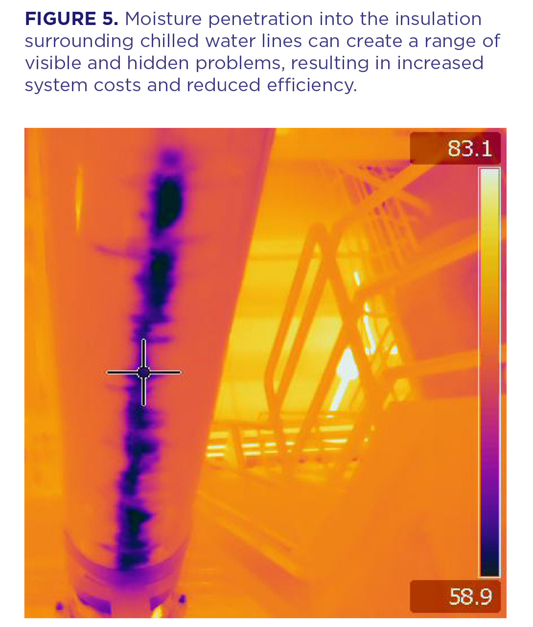
As mentioned, condensation on the outside of insulated pipes can lead to dripping, which may damage ceiling tiles, equipment, furniture, or anything located below the piping. Vapor penetration into the insulation also can saturate permeable insulation, allowing enough moisture to collect so that dripping occurs. Moisture intrusion in chilled water insulation can also create hidden problems in addition to the visible damage and dripping (Figure 5). Moisture intrusion into the insulation system increases the potential for pipes, fittings, and hangers to rust or corrode. It also may initiate CUI, depending on the type of pipe material used. CUI can remain hidden for years, ultimately leading to the need to replace piping along with insulation.
Inefficient insulation that has collected moisture may create thermal bridges, which are areas where larger amounts of heat move through the insulating materials, and can place additional strain on chillers and shorten the overall life span of the chilled water system. A less efficient chilled water piping system means more energy is required to maintain the desired temperature, leading to increased operating costs and reduced process control. Moisture in the insulation also can increase maintenance and repair requirements, further increasing operating costs and likely leading to replacement of the system earlier than anticipated—results probably not factored into initial system expense. Expenses including maintenance and repair costs can be estimated and included when determining initial system cost. This calculation will reduce the impact of these developments when they occur. Keep in mind that removing and replacing a failed insulation system can be three to five times the original cost of installing the system. Finally, moisture in insulating materials can support mold and mildew growth.
A Closer Look at Airports and Commercial and Industrial Facilities
Recent federal legislation is set to provide $25 billion funding to U.S. airports in the next few years to address infrastructure needs and other modernization efforts.5 These investments and related work highlight steps that can be taken when designing internal systems like HVAC elements to ensure long-term, efficient function and help protect chilled water cooling systems against known problems, including vapor penetration into insulation and development of CUI.
Designing the insulation to be used with chilled water piping is given specific attention in airport facilities and other commercial and industrial buildings. These facilities face a number of moisture-based challenges, which can lead to a range of problems that can shorten the overall life span of the system and facilitate formation of CUI.
Commercial buildings also may experience “idle building syndrome,” where the building is shut down and the air handlers turned off while the cooling system remains on. This exposes the chilled pipes to unconditioned air, which increases the likelihood of surface condensation. This situation may happen in a variety of commercial and industrial facilities beyond airports. When designing insulation to protect at-risk pipes from a range of conditions, it remains important to factor in all the conditions to help protect long-term, efficient function and prevent problems like CUI from developing.
Selecting Insulating Materials
Multiple factors must be considered when designing the insulation used with chilled water systems. Among these are location of the system, regional climate, type of building, if the system will be operational before the building is fully enclosed, and whether the air-handling system will be cycled on and off. With those factors to consider, ASHRAE suggests the most practical approach that is likely to be economical over the lifetime of the system is to use insulation materials with low to zero permeability.6
Other considerations for the type of insulation materials to be used include strength and durability of the product, and any safety considerations that need to be met. The durability of the insulation system is important, particularly in areas where the system is at risk of physical damage and especially when the weight of the pipe is resting on the insulation system at the supports. In a large, public facility, it may be important that insulation be noncombustible and have a flame spread index no higher than 25 and a smoke-generation index less than or equal to 50 when exposed to a flame.
One impermeable closed-cell insulation material commonly used on chilled water piping is cellular glass insulation—a foam that is manufactured from glass. It is resistant to moisture penetration in vapor or liquid form. It also is non-absorbent and non-wicking. When used indoors on chilled water systems, an additional jacket or vapor retarder is not required when the insulation joints are properly sealed. Correctly installed, cellular glass insulation has a demonstrated life span of more than 30 years.
In addition, cellular glass insulation is non-combustible and has a flame spread index less than or equal to 5, and a smoke generation index of 0. As a result, cellular glass insulation can help protect piping in the event of a fire. Cellular glass insulation is lightweight in comparison to its high compressive strength. Because of these qualities, cellular glass insulation is often used at pipe supports on chilled water lines.
Conclusion
There are multiple factors that must be considered when designing insulation to protect the performance of chilled water systems. Chief among these factors is the control/mitigation of water vapor migration into the insulation system. When designing a chilled water insulation system, identifying possible extreme conditions and additional challenges the system might face can help mitigate many of the risks to the system. Selecting an impermeable thermal insulation product will also help extend the projected life of the system.
References
1. ASTM International. (2022). Standard Test Methods for Gravimetric Determination of Water Vapor Transmission Rate of Materials (ASTM E96/E96M-22). https://www.astm.org/e0096_e0096m-22.html.
2. Adams, Ludwig. (1974). “Thermal Conductivity of Wet Insulations.” ASHRAE Journal. pp. 61–62.
3. Kehrer, M., H.M. Kunzel, and Sedlbauer, K. (2002). “Ecological insulation materials—Does sorption moisture affect their insulation performance?” Journal of Thermal Envelope and Building Science; L. Cremaschi, S. Cai, A. Ghajar, and K. Worthington, (2012). “Methodology to measure thermal performance of pipe insulation at below ambient temperatures.” ASHRAE RP 1356 Final Report; and Jerman, M., and Cerny, R. (2012). “Effect of moisture content on heat and moisture transport and storage properties of thermal
insulation materials.” Energy and Buildings.
4. Gusyachkin, A.M., et al. (2019). IOP Conf. Ser.: Mater. Sci. Eng. 570 012029.
5. Duncan, I. (December 16, 2021). “FAA awards first $3 billion in new airport infrastructure funds.” The Washington Post. https://www.washingtonpost.com/transportation/2021/12/16/faa-infrastructure-money-airports/.
6. ASHRAE. (2017). ASHRAE Handbook—Fundamentals (I-P ed.).