Designing District Energy Systems for Longevity
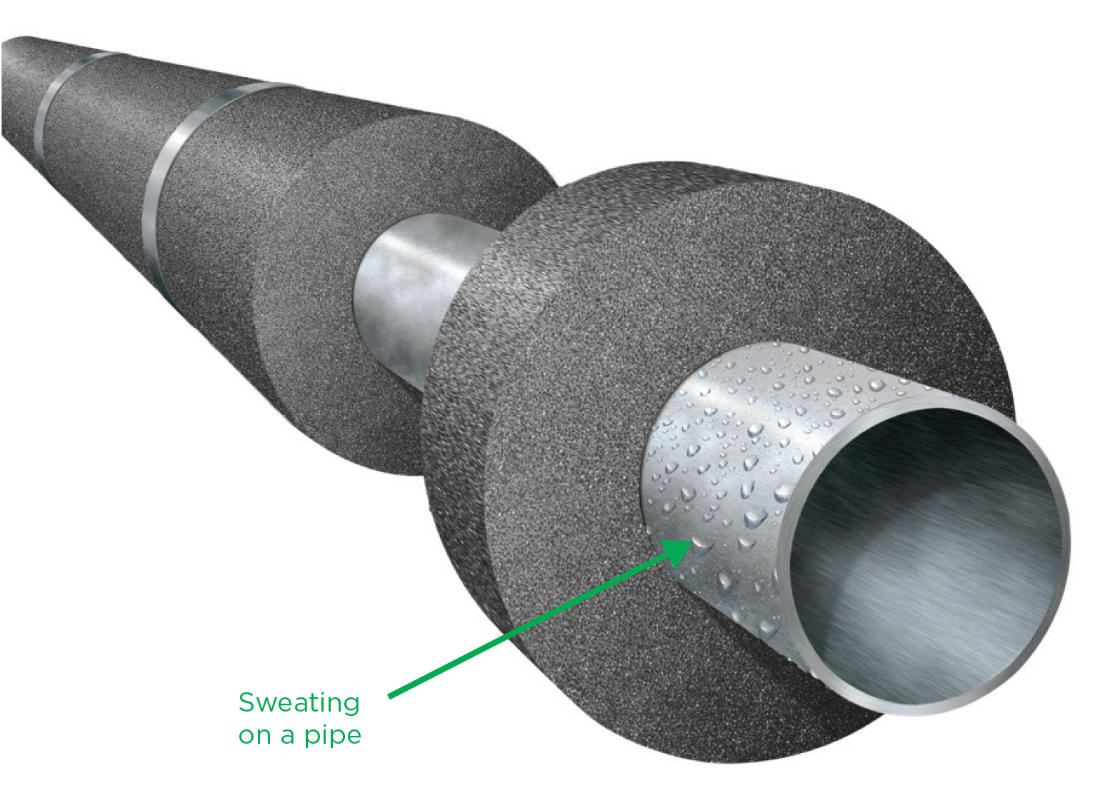
District energy systems are becoming more commonplace as a practical HVAC solution for populated environments with a high demand for heating and cooling solutions. Today’s universities, hospitals, and municipal complexes commonly rely on a district energy system’s central plant to generate chilled water, hot water, and steam, and distribute them via a network of pipes to energy users in the buildings throughout the district.
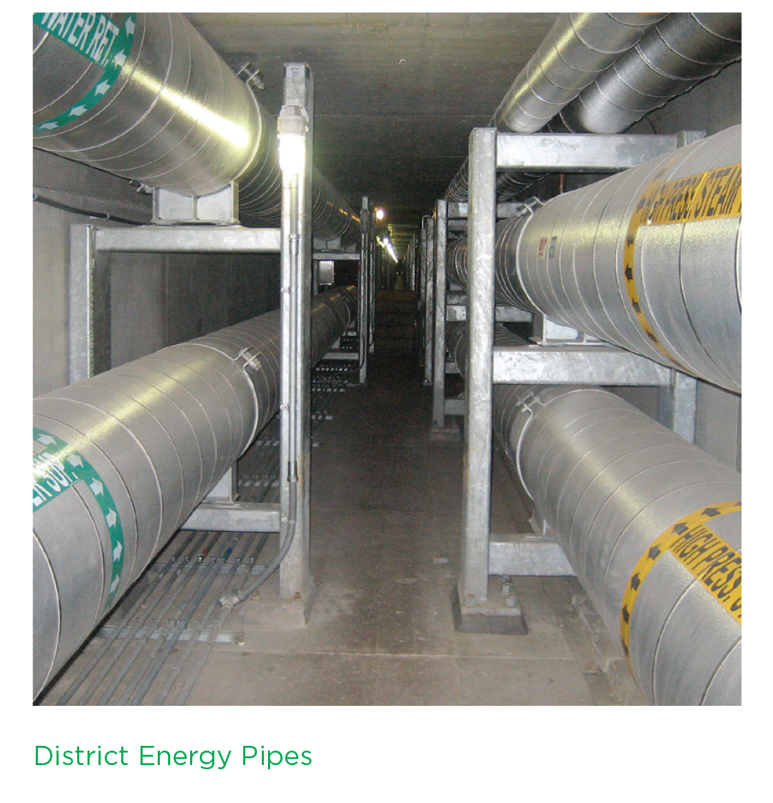
District energy system piping is usually “direct buried” under soil or housed in underground tunnels and vaults. These environments often can present harsh conditions that can lead to problems within pipe insulation systems, including reduced thermal performance, corrosion under insulation (CUI), and added stress to underlying equipment and infrastructure. These issues could be due to suboptimal material selection, improper installation, or damage that takes place during operation.
In this article, we will explore factors to consider regarding insulation systems to support the longevity and efficiency of district energy systems.
Challenges with Chilled Water Lines
The chilled water lines within district energy systems typically will operate within a given temperature range. This could be as low as 36°F (2°C) for chilled water supply lines and up to 55°F (13°C) for return lines. Given these below-ambient temperatures, there is usually an ever-present vapor drive that wants to condense water vapor from the air into liquid water condensation on the pipe’s surface. Insulation systems rely on the integrity of a vapor barrier to prevent water buildup from occurring within them. If that vapor barrier were to become compromised, the system would be subject to moisture intrusion that could bring about a variety of issues that could remain hidden for years before being discovered.
Moisture ingress into the insulating system is a key concern in chilled water applications. In the case of absorbent insulations, liquid moisture can collect within the insulation material. Insulation systems often rely on the presence of air gaps within their structure to maintain their declared thermal conductivity values. If these insulation materials become saturated with water, it leads to significant degradation of their thermal properties, resulting in thermal bridging, which can increase heat gain into the underlying chilled water lines. This situation can lead to energy losses and increased costs, as more energy is required to cool pipes back down to their intended operating temperature. It also puts added stress on equipment such as chillers, potentially degrading their service life.
Another byproduct of introducing moisture into an insulation system involves the potential for CUI. For corrosion of carbon steel to occur, certain ingredients must be present—the most fundamental of which are the presence of oxygen and an electrolyte (such as liquid water). Oxygen is almost always readily available, whether it be from the air or dissolved in water itself. Therefore, if liquid water is introduced onto a carbon steel surface, the risk of corrosion becomes immediately present. Corrosion can damage the outside of pipes over the span of multiple years; and, in the most catastrophic instances, it can result in failure of an entire piping system.
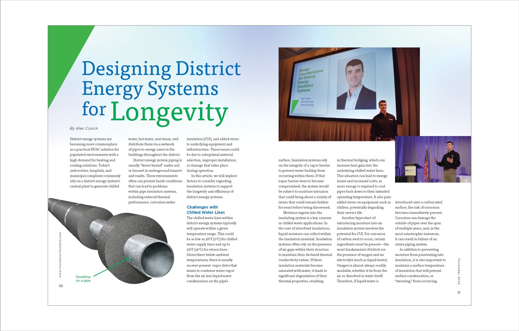
In addition to preventing moisture from penetrating into insulation, it is also important to maintain a surface temperature of insulation that will prevent surface condensation, or
“sweating,” from occurring. If water is allowed to condense on the outside of an insulation system, it can contact nearby metal equipment and lead to corrosion, or potentially work its way through a system’s vapor barrier, leading to the previously mentioned issues. The goal when designing an insulation system for chilled water lines is always to ensure that the surface temperature of the insulation system will be greater than the dew point of the surrounding air. One way to achieve this is to ensure a sufficient thickness of insulation material is used, based on the operating temperature and humidity of the local environment. This can be determined during the engineering design phase of a system through an energy analysis calculation.
Another design consideration that can affect the presence of surface condensation is the emissivity of an insulation system’s outermost surface. Emissivity is the relative effectiveness of a surface to emit and absorb heat by radiation. It is expressed as a ratio between 0 and 1 and is most relevant to the outermost jacketing to be used on an insulation system. The higher the emissivity, the more heat transfer will occur between the material and its environment via radiation. When considering chilled water pipes in warm environments, low emissivity jacketing materials—such as aluminum and steel—will absorb less heat from their surroundings via radiation, which will result in a lower jacketing surface temperature. Conversely, high emissivity jacketing materials—such as PVC and ASJ—will absorb more heat from their surroundings, yielding an overall higher surface temperature for the same system and potentially preventing surface condensation from taking place.
These complications around moisture intrusion can vary in significance based on the geographic location of a project. In cooler and more arid regions, there may be less humidity present within the air to contribute toward a vapor drive into an insulation system. However, in warmer and more tropical environments, vapor drive tends to be a much more significant issue that requires forethought and design consideration. As a best practice, it is advised to consider the worst-case conditions for a given environment when conducting energy calculations to mitigate the risk that moisture intrusion may present for a below-ambient system.
Challenges with Hot Water and Steam Lines
Pipes that carry hot processes such as steam and hot water are not subject to vapor drives in the same way that chilled water lines are, but they have equally significant risks that can lead to system complications if not designed around. As we will discuss in later sections, there are other scenarios that can lead to unexpected moisture ingress into an insulation system. If liquid water were to penetrate a hot-water or low-pressure steam line, it could present an even greater risk for CUI to occur than with pipes operating at chilled water temperatures. This is because electrochemical processes, like the formation of rust, occur more rapidly at higher temperatures. This means that if moisture penetrates an insulation system and contacts the surface of a steel pipe, and the pipe is operating at a low enough temperature for water to remain in liquid form (as with hot-water and low-temperature steam lines), then corrosion can emerge as a significant threat to the longevity of the piping itself.
In the case of high-pressure steam lines, piping is often operating at a temperature that is too hot for water to remain in liquid form to come into contact with it. In some regards, this alleviates the potential for corrosion to occur, as liquid water is a key ingredient for corrosion to take place. However, if a large amount of moisture were to penetrate such a system while not in operation, it could lead to other, more immediate issues. In this case, if insulation were to become saturated with water when the system is out of service, and the system is then quickly brought up to operating temperatures over 400°F (204°C), the heat generated could rapidly convert the water in the insulation to high-pressure steam, potentially destroying the insulation system as the steam is violently driven away from the hot pipe. This places increased emphasis on the performance of the moisture or vapor barrier to mitigate the risk of moisture penetration into a system.
One more consideration for high-temperature lines is the potential expansion that a stretch of piping will experience while in operation. Steel, like most other materials, will expand in size as it increases in temperature. For a hypothetical 100-foot run of carbon steel pipe on a steam line that increases from 70°F (21°C) to 400°F (204°C), the run of piping may experience an increase in length of about 2.6 inches. Underground expansion loops, or zees, are often installed in piping systems as locations intentionally designed to bend and allow this expansion to occur without putting stress on or damaging the piping itself. It is important that whatever insulation system is installed, it is designed in a manner to allow for this movement to occur at these critical locations, otherwise they become prime locations for damage to the vapor/moisture barrier to occur.
Challenges with Vaults and Tunnels
The piping networks that make up district energy systems typically travel from energy supplier to building users through an underground network. In many cases, this is via underground enclosed spaces, such as vaults and tunnels, which present additional challenges to insulation systems on pipes within them.
Depending on the size of an underground tunnel, it could be periodically accessible to maintenance activities that expose the insulation system to unanticipated foot traffic. It also is not uncommon for vermin to find their way into these tunnels and burrow into any materials they can. These points, while easy to overlook, place an importance on insulation materials to be durable enough to withstand such possible sources of damage.
Another unplanned-for event that often impacts tunnels and vaults is flooding. While tunnels are not typically designed to allow groundwater into them, the reality is that over the life of an underground system it becomes increasingly common for flooding to occur within these underground spaces at some point. This presents a much more direct source of water intrusion, which can lead to exacerbated complications along the same lines as the ones discussed around vapor drive for chilled water lines, or moisture ingress for hot-water and steam lines.
Challenges with Direct Burial Lines
Alternatively to vaults and tunnels, it is common for district energy piping systems to be buried directly within ground soil. This can bring about separate environmental challenges to be considered.
One example involves the compressive forces associated with soil loads and live loads. Soil load refers to the weight exerted on a pipe from the above-soil backfill when a pipe is buried. It increases with soil density and burial depth. Live load refers to the weight transferred indirectly to piping from heavy or moving objects that may be present on the surface of the ground itself. Soil load will increase with the relative mass and movement of objects in question, as well as be greater for pipes of larger outer diameter or shallower burial depth. For piping systems traversing underneath roadways, this becomes a critical design element, as the added weight and movement from vehicles presents a significant source of forces that should not be overlooked. It is important to consider both the soil and live loads that a direct burial system may be subject to and choose an insulation material with the compressive strength needed to resist them.
Another factor to consider for direct burial lines is the hydrostatic pressure the system may experience from groundwater. Hydrostatic pressure refers to the pressure that is exerted at a given point within a fluid due to the force of gravity. This challenge is most significant in locations of high water tables and heavy seasonal precipitation. If moisture is present in the soil, the water pressure will increase as a function of soil depth. If a permeable insulation is present and contains weak or poorly installed joints in its moisture/vapor barrier, this water pressure has the potential to drive moisture into underground insulation systems, where it can lead to future complications.
Considerations around Insulation Systems
It should be clear by now that district energy piping systems face multiple challenges that can affect their long-term performance. The insulation systems on these pipes should be designed with these challenges in mind to achieve the best and longest lasting performance possible. An important first step in designing a successful insulation system can take place during material selection. If a pipe will be subject to significant soil loading or foot traffic, consider choosing an insulation material that has the compressive strength to withstand the weight load it will be subject to.
Insulation materials with a zero or near-zero permeability rating can provide added protection against vapor drive that may be present in an ambient environment. Likewise, nonabsorbent insulation materials can resist retaining and becoming saturated from sources of water present. In either case, the total performance of the vapor/moisture barrier of a system is an integral part of the system’s longevity, so it is important to ensure appropriate and compatible accessory materials are used for the system in question.
Of course, even the best-designed insulation system will only perform as well as it is installed. This is why it is critical to ensure best practices for application of materials are being followed in the field through the utilization of available training courses and a robust inspection program.
Through proper engineering design, sound insulation material selection, and optimal installation techniques, district energy insulation systems can be relied upon to deliver reliable and efficient energy to our modern world.