Electric Traced Systems
This article is a guide to determine where and when electric tracing may be an option. It will also address the design and installation practices of electrical heat-tracing systems, along with insulation requirements. This is to serve as a guide only, since many special conditions may not be covered in this article. Impedance, skin electric current tracing and induction heating aren’t addressed here.
Electrical heat traced systems are used frequently for:
- freeze protection of pipelines and equipment.
- maintaining a specific temperature of process systems.
- changing the temperature of a process.
Electrical heat-tracing is gaining popularity over steam heat-tracing for the following reasons:
- Electrical traced systems can be controlled with fewer temperature variations.
- Steam-traced systems usually respond more slowly to changing heat demands.
- During cold weather, the steam equipment may become overloaded at a time when the traced systems require freeze protection.
- Steam traced systems require design considerations for evacuating the condensate. Steam trap locations and the pipeline, tracer configuration is critical on steam tracing.
- Electrical traced systems only need to be turned on when protection is required, thereby saving energy.
- Where the traced systems are to be applied for the purpose of freeze protection or where the process temperature is below approximately 300 degrees fahrenheit (F) (149 degrees celsius[C]), electric tracing is usually the most cost effective method. They’re easier to install and maintain.
Electric tracing for freeze protection is perhaps where this type of system is most widely used. This protection is usually where water or a process liquid may not flow for a period of time and the temperature may be below freezing for several hours or days. There are also conditions where a process material has a high viscosity or solidifies at lower temperatures and require heating in order to pump from one location to another.
Considering Electric Tracing
Many years ago, at the direction of a young engineer, a new safety shower was installed on an acid chemical plant in Ohio. It was some distance from the main buildings. Fifty-pound steam was available in the area so the water line to the safety shower was traced with steam. When visiting the plant in mid-winter, with snow on the ground, this young engineer was escorted by the superintendent to review the work progress. The superintendent wanted to demonstrate the use of his new safety shower by turning it on. A cloud of steam and scalding condensate came forth from the showerhead. Luckily, nobody was under the shower, though it did clear the snow in the immediate area. Proper design with a steam pressure reducing station may have eliminated the problem. However, electric tracing the water line should have been considered.
Water lines don’t always have to be traced and insulated, but water must be flowing in the line. This is known as bleeding the line. Tests indicate that the flow versus the outside temperature to prevent freezing is approximately a straight line function, which varies from no flow required with an outdoor temperature of 33 degrees F to 40 degrees F to an outdoor temperature of minus 20 degrees F or below.
Figure/Table 1 illustrates the minimum flow or bleed rates of water in gallons per minute, required for each 100 feet of pipe.
Process Systems
Process systems should be evaluated not only on the extreme cold outdoor temperature, but also on the time duration the process system is exposed to the extreme temperature.
The best way to explain the design process is by the following example.
A client in Billings, Mont., has a 4-inch water pipeline that will be shut off (the pipe can’t be drained or bled) over an extended period of time during the winter months.
Design Data
- The minimum ambient temperature is minus 15 degrees F.
- Wind speed is 20 mph.
- The line is welded, schedule 40, carbon steel and 300 feet long.
- The line has 2 gate valves and 6 flanges (150 pounds).
- Maintain water temperature at or above 35 degrees F.
- Water entry source temperature is 55 degrees F.
- Climactic data for that area indicates that the temperature can be minus 15 degrees F continuously for 24 hours.
Will the water temperature drop below 35 degrees F in the 4-inch pipe during the 24 hour period if it’s NOT insulated? To find out, follow these steps:
- All materials contain energy or commonly known as latent heat. The latent heat will vary according to the material and temperature. In this case the material is water. See technical manuals for the latent heat of other materials.
- See Figure/Table 3. At 55 degrees F, the water weight is 62.38 pounds/cubic foot and the latent heat is 23.06 Btu/pound. At 35 degrees F, the water weight is 62.42 pound/cubic foot and the latent heat is 3.02 Btu/pound. The difference in the weight of water is so slight that it can be disregarded.
- Multiply the weight of the water per foot in the 4-inch pipe (Figure/Table 2) by the latent heat; 5.51 x 23.06 = 127 Btu/hour /foot of latent heat at 55 degrees F. 5.51 x 3.02 = 16.6 Btu/hour/foot of latent heat at 35 degrees F.
- Subtract 16.6 from 127 = 110.4 Btu/hour/foot.
- Go to the 3E Plus® 3.0 program and tab the Energy Loss/Gain button.
- For this exercise, indicate perlite insulation.
- For the finish, it’s 0.1 emissivity for plain aluminum (type finish has almost no effect).
- Select the horizontal cylinder for the surface geometry.
- Be sure to indicate one hour in the Annual Operation Box.
- The wind speed is 20 mph. An accurate average wind speed in this case, in mid-winter, can increase the heat loss from 12 percent to 4 percent, depending on the insulation thickness selected. (See Figure/Table 3 for reference only).
- For pipe size, indicate 4-1/2 inches. The traced system will require oversized insulation to accommodate the tracer. Run the program with water and extreme ambient temperatures of 55 degrees F and minus 15 degrees F respectively. The program data indicates 19.56 Btu/hour/foot. Also run a water and ambient temperature of 35 degrees F and minus 15 degrees F respectively. The program data indicates 13.84 Btu/hour/foot.
- Remember, we can only lose 110.4 Btu/hour/foot to stay at 35 degrees F or above.
- Find the average heat loss between 55 degrees F and 35 degrees F (19.56 + 13.84/2 = 16.7 Btu/hour/foot).
- The 3 inches of perlite silicate insulation will allow 16.7 Btu/hour/foot. Dividing the allowable Btu of 110.4 by 16.7 = 6.61 hours when the pipe temperature will reach 35 degrees F. The 6.61 hours is far short of the 24 hour period.
- Run a program using the same data, but substitute 3 inches of PIR (polyisocyanurate) insulation.
- The data indicates 7.550 and 5.454 with an average of 6.5 Btu/hour/foot heat loss. Dividing the allowable Btu of 110.4 by 6.5 = 17 hours. Again, this is still short of the 24 hour period.
- Additional programs can be run using insulation with improved thermal conductivity, such as phenolic, and increasing the insulation thickness. However, the results for this example are impractical.
- Electric tracing the 4-inch pipe appears to be the viable option.
Determining the Appropriate Heat Tracer
Next, determine the appropriate type electric heat tracer for the following project.
-
(a.) Find the wattage required for the 4-inch pipe. Refer to Figure/Table 5. Design for 1.5-inch-thick insulation with a differential temperature (Delta T) of 35 degrees F and minus 15 degrees equals 50 degrees F. Note that temperatures aren’t shown, so adjust wattage by interpolation.
(b) Figure/Table 5 indicates under 4-inch pipe a heat loss of 4.1 watts/foot. Since oversize insulation is recommended on traced systems, consider using insulation with an I.D. for 5 inch pipe. Interpolate the average of 4 and 6 inch pipe (4.1+5.6/2 = 4.9 watts/foot).
(c) Refer to Figure/Table 4. The multiplying factor for PIR at 100 degrees F mean temperature equals .76. This reduces the wattage to 4.9 x .76 = 3.8 watts/foot.
(d) The wind conditions are greater than stated for the wattage in Figure/Table 5. Therefore, refer to Figure/Table 7. With 1-1/2 inch thick insulation, the table indicates only a 1 percent difference between a wind velocity of 15 mph and 20 mph. The required wattage can be rounded off to 3.9 watts/foot.
(e) Find the wattage required for the valves and flanges. Refer to Figure/Table 6. The line has 2 gate valves and 6 flanges. Again use the average between 4- and 6-inch pipe for oversize insulation. For the gate valves, 5.5+ 6/2 equals 5.75 x 3.9 watts/foot = 22.5 watts/valve.
-
For 150 pound flanges, 1.4 x 3.9 watts/foot = 5.5 watts/flange. Total wattage for fittings is 2 x 22.5 equals 45 watts, plus 6 x 5.5 = 33 watts.
(f) The tracer must provide 3.9 watts/foot for a total length, including valves and flanges of 300 + 5.75(2) + 1.4(6) = 320 feet.
For conditions similar to the previous example, when designing for freeze protection, where the power output is below a constant 10 watts, the cable (wire) temperature can be held below 212 degrees F (100 degrees C). Therefore, almost any type insulation can be applied without exceeding the temperature limit.
- After reviewing the various types of heat tracers that follow, it appears that the most cost-effective selection is the self-limiting heat-tracer.
- The wire size and type, and voltage required can be determined by the cable manufacturer given the previously listed data with the selection of insulation and thickness.
- In some cases, where a concentration of heat may be necessary and spiral wrapping isn’t an option, the wattage (heat transfer) can be increased up to eight times by encapsulating the tracer with heat transfer cement (also commonly known as heat transfer medium [HTM]. Contact HTM manufacturers for optimum heat transfer requirements.
- When product other than water is in the pipe, the evaluation becomes more complex and beyond the scope of this article.
- Equipment, tanks and vessels can be evaluated in much the same way as piping. The wattage (energy) is evaluated in square feet of surface area instead of lineal feet of pipe. Refer to Figure/Table 8.
- The wattage derived from this guide is under ideal conditions and doesn’t account for insulation systems with insulation voids, cracks or open joints. HTM manufacturers may provide a wattage percent increase to compensate for any deficiencies.
- The type of insulation and thickness for the pipe will have a direct effect on the wattage (energy) required. The thermal conductivity of insulation may only be one consideration when selecting the most cost-effective material. A hostile environment may require insulation that’s completely impervious to moisture and mechanical abuse.
Selection of Heat Tracing
Electrical heat-tracing material consists of a resistance wire, an insulation covering, a grounded outer metal sheath and usually an outer jacket. The heating tracer may be a cable, strip or tape. They can be applied to pipes, valves, flanges, vessels, tanks and other surfaces where heat is required.
The principal considerations in selecting the correct heat tracer is:
- the energy (wattage) required of the system to be traced.
- the electrical classification in areas where special environmental conditions exist.
- the temperature limits for the tracer. This is usually determined by the cable jacket material.
- the cost considerations.
- length of pipe, including valves and flanges, to be traced and length of tracer on equipment.
Typical Electrical Heat-Tracers
Single Conductor Resistance Wire
- This should be limited to piping systems operating no greater than 212 degrees F (100 degrees C) because of wattage limitations and possible damage to the wire jacket.
- The maximum wattage is determined by the jacket limitations of 390 degrees F (200 degrees C).
Self -Limiting Heat-Tracers
- Since they are parallel resistance configuration, the tracer can be cut to any length without changing the ratings. This provides easy circuit fabrication in the field.
- Overheating the pipe is almost impossible because the tracer heat output is reduced as the pipe temperature increases.
- This cable can supply up to 10 watts per foot at operating voltages to 277 VAC.
- They can maintain temperatures as high as 250 degrees F (121 degrees C) and 375 degrees F (191 degrees C) when not operating.
- They shouldn’t be used on piping held at a temperature greater than 151 degrees F (66 degrees C) because of wattage limitations.
Mineral-Insulated (MI) Heat Tracers
- Mineral insulated cables are recommended for systems requiring high wattage (up to 80 watts per foot), and exposure to high temperatures, up to 1,100 degrees F (593 degrees C).
- These cables are damage resistant and used in classified hazardous areas.
- The cable sheath is completely waterproof.
Heat-Tracing Strip
- Generally, heat tracing strips shouldn’t be used on pipe operating at temperatures greater than 122 degrees F (50 degrees C) since damage could occur to the tracer sheathing.
- This tracer is recommended for PVC piping and equipment because the wide heat dissipation area allows the tape to be heated slightly higher than the heating surface.
- Maximum wattage is 24 watts per foot.
- It shouldn’t be considered for use on piping with valves and flanges.
- The strip can be cut to any length without changing wattage and voltage ratings.
The previous information is for general consideration only, and may not agree with every electrical heat- tracing manufacturer.
Safety Issues
The National Electric Code (NEC) that’s referenced in the Occupational Safety Health Administration Section 1910.309 mandates guidelines that must be followed. It’s important that the engineer review the latest requirements with the heat-tracing manufacturer.
There are several basic safety items that must be considered in heat tracing. The following lists a number of those considerations.
- All electrical heat traced systems shall be conspicuously identified as "electric traced" a minimum every 10 feet outside the insulation finish.
- The heat-tracer shall be secured to the pipe surface at least at 12 inch spacing.
- All heat-tracer connectors and splicing concealed by the insulation should be marked as such outside the insulation system.
- There should be lock-out provisions for system maintenance.
- Electric heat tracers shall have a continuous metal sheath, wire braid or cover that’s grounded.
- Electric heat tracers shall be approved for the class they’re to be located.
- The manufacturer shall determine that the tracer sheath temperature isn’t exceeded.
- Where flammable material is heated, the tracer must not exceed 80 percent in degrees C, the minimum auto-ignition temperature.
- The thermal insulation must be rated for the maximum temperature of the electric heat-tracer.
- Electrical heat-tracers shall not cross over itself and be separated by a minimum of 1 inch, since this condition can cause excessive overheating to the sheathing and eventual failure.
Installation Practices
(Refer to Figures 9 through 11)
Notes:
- Where one electric heat-tracer is used, it may be installed on either side (Figure 9).
-
- Electric heat tracers shall be installed in a air plenum between the pipe and the insulation. Grooving the insulation to accommodate the tracer isn’t acceptable.
- Only preformed pipe insulation should be used. Blanket or loose insulation will close the space.
- Generally, oversize insulation isn’t required for heating strips, providing the preformed insulation can be tightly closed at the joints.
- Electric traced piping shall be supported outside the insulation.
- Tracers should be secured in three places at pipe elbows.
- The heat tracers shall be installed on valves and flanges so that they can be pulled aside for maintenance.
- The pipe and equipment surface must be clean and free of rust, grease or any foreign matter.
- Install the tracer before cutting the length. There should be no excess length.
-
- Only the cold part of the tracer should pass through the insulation with a conduit.
- In areas where the insulation can get wet, seal around the conduit where it passes through the insulation finish with a bead of silicone sealant.
-
- The tracers can be temporarily secured to pipe with stainless steel wire. After adjustments with the tracer is completed, secure the tracers with stainless steel banding a maximum 12 inches on center.
- Where the tracer doesn’t make contact with the heating surface, additional banding may be required.
- Where the heat tracer is spirally wrapped, securement is only required at the each end.
- Where a space can’t be avoided between the tracer and the surface, pack the void with heat transfer cement.
- Screws shall not be used to secure insulation finishes on an electric traced system.
The electric heat-tracer system should be installed correctly by an electrician. However, the insulation contractor shall also install the insulation system correctly to prevent the intrusion of moisture, so the traced system can perform at its optimum design level.
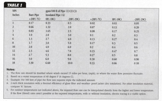 Figure 1
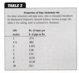 Figure 2
 Figure 3
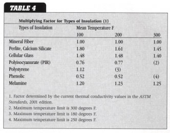 Figure 4
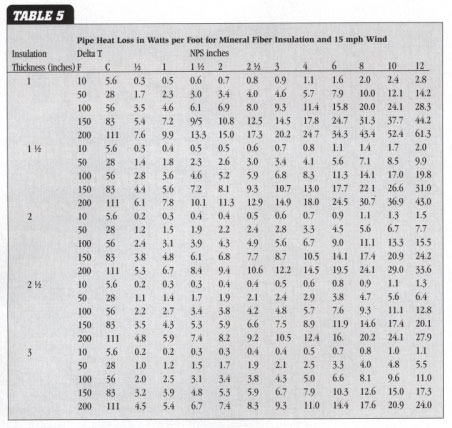 Figure 5
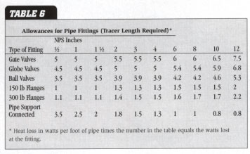 Figure 6
 Figure 7
 Figure 8
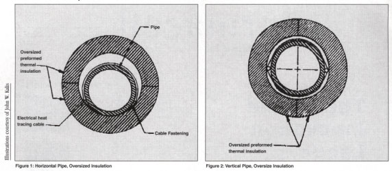 Figure 9
Left: Horizontal pipe, oversized insulatuion. Right: Vertical pipe, oversized insulation.
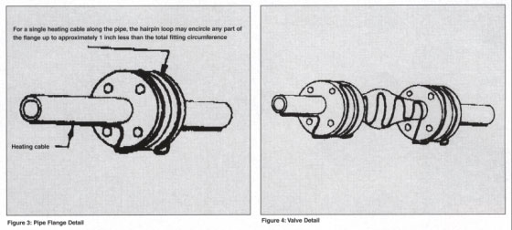 Figure 10
Left: Pipe flange detail. Right: Valve detail.
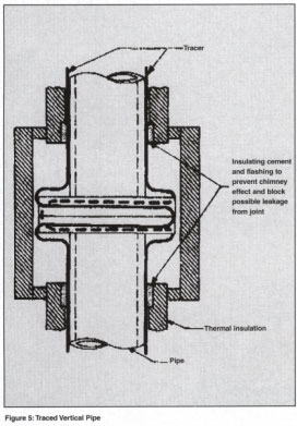 Figure 11
Traced vertical pipe.