Hot or Cold…
It is not intended that complicated thermodynamic principles be presented here to describe condensation as a desired function of a process where a liquid component is removed from a vapor. Instead, we are going to discuss some of the bad things that can result when a liquid is condensed from a vapor when the insulation system is not keeping surface temperatures above the dew point for a component in the vapor phase.
What Happens With Cold Fluids?
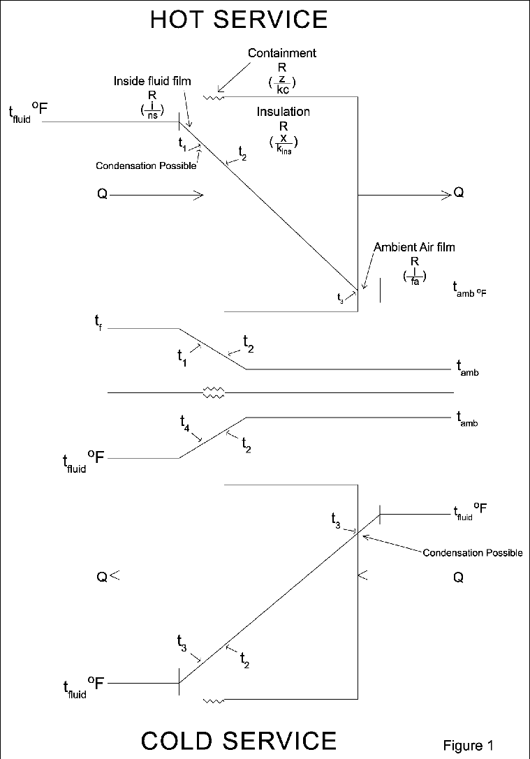
When a cold fluid is being transported through a system exposed to the ambient air, heat is being transferred from the air into the fluid in the system and the following occurs:
- A temperature drop across the surface air film on the jacketing material
- A further temperature drop across the insulation system
- Yet a further temperature drop across the containing material
- And finally another temperature drop across the fluid film into the fluid itself.
In this series heat flow path, the surface temperature of the jacket is therefore below the temperature of the ambient air. Depending on the value of the surface film resistance and the relative humidity of the ambient air, that surface temperature may be below the dew point temperature, and condensation will form on the outer surface of the system.
There is also a parallel heat transfer path, essentially the same except there is no insulation system in place. In this case, the thermal resistance of the outside air film is the major component and the temperature drop across the film is much greater. This means that the surface is much colder and condensation is more severe. The problem here is that condensed water may contribute to insulation system degradation and corrosion is more likely to occur.
What Happens With Hot Fluids?
When a hot fluid is being transported through a system exposed to the ambient air, heat is being transferred from the fluid in the system into the ambient air and the following occurs:
- A temperature drop across the fluid film inside the containing material
- A temperature drop across the containing material
- A further temperature drop across the insulation system
- And finally, another temperature drop across the fluid film into the ambient air.
In this series heat flow path, the surface temperature of the inside pipe surface is therefore below the temperature of the fluid in the pipe. When that hot fluid is in the vapor or gaseous phase, the inside surface temperature may be below the boiling point temperature of the fluid, and condensation will form on the inner surface of the system.
There is also a parallel heat transfer path, essentially the same except there is no insulation system in place. In this case, the thermal resistance of the inside vapor film is the major component and the temperature drop across the film is much greater. This means that the inside surface is much colder and condensation is more severe. The problem here is that condensed vapors may contribute to corrosion and shorten service life of the containing material.
Figure 1 depicts the cross section of both hot and cold systems showing temperature drops across components of each. The key to finding a solution to prevent condensation is to calculate the thermal resistances of each component with special interest to the surface film coefficients on those sides where condensation is possible so that the surface temperature will be above the critical value for the given system. In series heat flow, the thermal resistances are additive:
Rt = 1/ho + t/kins + x/kcon +1/hi
Where:
- Rt is total system resistance, sq ft*hr/Btu
- ho is the surface film coefficient on the side of the system exposed to ambient air, Btu/(sq ft*hr)
- t is the thickness of the insulation, in inches
- kins is the insulation thermal conductivity, Btu*in/(hr*sq ft*ºF)
- x is the wall thickness of the containment, in inches
- kcon is the thermal conductivity of the containment material, Btu*in/(hr*sq ft*ºF)
- hi is the surface film coefficient on the interior side of the system, Btu/(sq ft*hr).
Again, in series heat flow, the quantity of heat flowing from hot to cold is the same through each component. Please remember that if the quantity of heat flowing has a negative value, it means that the heat flow is going in the other direction. For our cold service condition, the value of t3 will be lower than ta, making Q negative, which means that heat is flowing from the ambient air into the system.
Q = (t3 – ta )/( 1/ho) = (t2 – t3)/ (t/kins) = (t1 – t2)/ (x/kcon) = (tf – t1)/ (1/hi) = (ta – tf)/ Rt
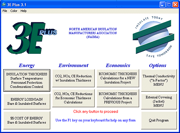
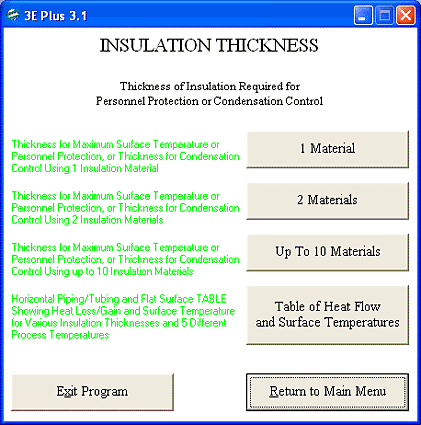
The North American Insulation Manufacturers Association (NAIMA) introduced a sophisticated computer program many years ago to help architects, engineers, designers, insulation manufacturers and contractors select the appropriate insulation thickness for almost all of the situations for which a thermal insulation system is being considered. This program is entitled 3E Plus®. Figure 2 shows the home page of this program. Note that, in the energy column in the insulation thickness box, condensation control is presented. Clicking on this box generates the next screen (Figure 3) for the thickness of insulation required for personnel protection or condensation control. Most of the time we will be dealing with a single insulation material; so we click on that box and generate the next screen (Figure 4).
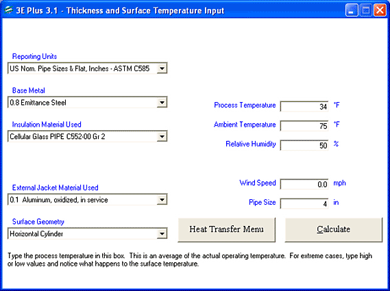
Note that on the left side of this screen, the boxes have a dropdown arrow at the right edge. Clicking on the arrow presents the drop-down menu for the user to select the appropriate inputs. There are four choices for reporting units. There are four choices for base metal based on the emittance of the containment material. Users have the option to include any containment material provided they supply the emittance value for it. There are 30 choices for the insulation material. If the one to be used is not in the list, one goes back to the home screen and selects the thermal conductivity option to include it in the program. There are 14 options for the external jacket material. If the one to be used is not in the list, it can be added by selecting the external covering menu from the main screen.
Cold Service
The boxes on the right side of this screen are used for inputs by the operator. At this point, the program applies to either personnel protection or condensation control. Both of these depend on the calculated value for the surface temperature of the external jacket. Personnel protection implies an elevated temperature from the contained material that could cause a burn from contact. Condensation control, on the other hand, implies a temperature below ambient that could permit condensation to form on the jacket. At this point let us assume that the fluid temperature in our system is at 34 F. Enter this value in the box. (A new screen is generated.) The third box down is now titled relative humidity. The user must consider carefully the value to be used for the ambient temperature.
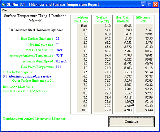
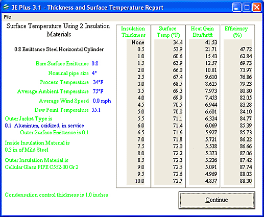
If the system is located outdoors, then the value to be used should represent the design condition for summer hours applicable to the geographic location. If the system is indoors, the highest design value for indoor summer temperature should be used. Let us use 75 F for ambient temperature. The final variable affecting the surface film resistance is the wind speed. The higher the value of wind speed, the lower the surface film resistance and therefore a lower temperature drop across it results. A zero value for wind speed would reflect the design for worst conditions. For now we input a 4-inch pipe size. Now we click on the calculate box, and the thickness and surface temperature report (Figure 5) appears. The program calculates the dew point temperature at 55.1 F, and the surface temperatures and heat gains for insulation thicknesses from zero to 10 inches. It then selects the surface temperature next higher than the dew point temperature. In this case it was 60.8 F for the 1-inch thickness.
It is noteworthy that this program makes two assumptions: 1) there is no significant temperature drop across the inside surface film, and 2) the thermal conductivity of the containment material is so high and its thickness is so thin that there is no significant temperature drop across the containment material either. Click on file on the task bar at the top of Figure 5, and you may select print or save. Selecting the print option generates the written report.
Let us take a few minutes to test your feel for how the insulation thickness needed to prevent condensation will change when we alter one input variable while keeping all the others the same as in these examples. (Write "increase," "decrease," or "not change," and see the answers at the end of the article.)
1. The insulation material is one with a lower thermal conductivity; so the thickness may__________________________.
2. The jacket emissivity is higher than 0.1; so the thickness may__________________________.
3. The process temperature is less than 34 F; so the thickness may__________________________.
4. The ambient temperature is higher than 75 F; so the thickness may__________________________.
5. The relative humidity is higher than 50 percent; so the thickness may__________________________.
6. The wind speed is more than 0 mph; so the thickness may__________________________.
7. The pipe size is larger than 4 inches IPS; so the thickness may__________________________.
8. The surface geometry changes to top of tank; so the thickness may__________________________.
Hot Service
In hot service, it is the temperature drop across the inside air film which must be considered. Again, the temperature drops occur across the inside film, the containment material, the insulation (if present) and the outside ambient air film. The 3E Plus computer program does not include the resistances for the inside surface film and the containment; so it may not be applicable for some solutions in this service.
In this case, we need to rely on some other computer program. ASTM C680-03, "Estimate of the Heat Gain or Loss and the Surface Temperatures of Insulated Flat, Cylindrical, and Spherical Systems by Use of Computer Programs," is available. In this instance, there appears to be an assumption also made that the thermal resistance of the containment is negligible. This program does provide sophisticated approaches for determining the surface conductances (due to convection, conduction and radiation). Caution is suggested for users to recognize that both the inside and outside film conductances should be considered.
Section 6.3.2 of the ASTM Standard contains the statement "For the computer programs, the inside surface conductance, hi can be assumed to be very large such that Ri = 0, and t1 =ti is the given surface temperature." Purists may also include the containment as a poor insulation material adding its layer to the total heat flow path and establishing its thermal conductivity equation. The materials that could be within a contained system are almost infinite in composition, service conditions and flow rates, and the internal surfaces can be subject to roughening in service. This strongly suggests that finding a good solution for controlling unwanted condensation from vapors in contained systems requires competent engineering skills to define the operating conditions, materials and ambient conditions, and that serious consideration be given to quality assurances that the installation reflects excellent workmanship so that the affects of parallel heat flow paths are minimized.
Condensation control in hot service requires that the inside surface temperature of the containment be above some critical temperature so that fluids in the vapor phase do not undergo a phase change and form liquid on the surface.
Summary
Condensation happens, and can happen fairly easily if the insulation system specifier and/or installer does not specify and install the right combination of insulation and jacketing materials to prevent it from happening. Unwanted water, as we all know, is an enemy. Condensation is destructive to the process and the materials surrounding the system. An insulation system specified for process control or personnel protection may or may not handle the condensation issues given what is happening either to the inside or outside of the system. As stated above, controlling condensation requires competent engineering and excellent workmanship so that neither the process nor insulation system is compromised.
Answers: 1. Decrease. 2. Decrease. 3. Increase. 4. Increase. 5. Increase. 6. Decrease. 7. Not change. 8. Increase.

