Insulation and Lagging in Power Plants
If Congress passes the Clear Skies Act, power plants will be making extensive capital expenditures on equipment upgrades to dramatically reduce air emissions. Insulation and lagging systems are a big part of the puzzle. Here are some things to keep in mind for equipment upgrades and new installations.
In July 2003, President George W. Bush announced that the Clear Skies Act would dramatically improve air quality in every region of the country and dramatically reduce air pollution from power plants by 70 percent. The Clear Skies Act would cut sulfur dioxide (SO2) emissions by 73 percent, nitrogen oxides (NOx) by 67 percent, and mercury emissions by 69 percent by the year 2018. This means cleaner air and healthier forests, lakes and estuaries.
It also means that the power-generating industry is going to spend a lot of money in the next 12 years on upgrading their steam-generating boilers or adding on very expensive air pollution equipment such as precipitators, bag houses, scrubbers and/or selective catalytic reducers.
Because insulation and lagging are key components of a steam-generating boiler or air pollution system for saving energy and for thermal efficiency, the power-generating industry needs to pay attention to the insulation and lagging systems being designed and installed. The industry needs cost-effective insulation and lagging systems that are installed correctly and thermally efficient.
During the next five years the power-generating industry is estimated to spend millions to repair or completely replace the insulation and lagging that has already been installed on their new selective or non-selective catalytic reducers, steam-generating boilers and wind boxes due to improper installation and design. Paying attention to the design and installation of insulation and lagging can help you save money and still meet your thermal requirements.
Choosing the Correct Insulation
The average maximum temperature at a steam-generating facility between the boiler exit flue gas and air heater, or between the air heater and the wind box, is between 500 F and 700 F. This is why it is so important for those working in the power-generating industry to be aware of the different insulation types. If you are basing your selection solely on thickness and K-value (insulating value), then almost all of the insulation types commonly selected-mineral fiber board, calcium silicate block and ceramic fiber board-could be used to insulate a steam-generating boiler, wind box, air heater, economizer, precipitator or bag house. See Figure 1. This is because all insulation types at mean temperature (insulation thickness calculations and K-values are always based on mean temperature, not operating temperature) have about the same K-value.
It is also interesting to note that insulation K-values or thermal conductivity values have not improved significantly during the past 30 years. This is why R.L. Schneider, a pioneer in heat transfer calculations, once wrote, "…since it is harder to keep improving insulation by decreasing the K (thermal conductivity), let’s increase the thickness when necessary."
In order to determine the proper insulation material when the K-values are about the same, you must look at the differences in the materials themselves and their impact on design and labor costs. For example, if you were choosing an insulation material for a top surface area that is to be designed to sustain foot traffic, you should know that:
-
Calcium silicate block (meeting ASTM C533) can be fragile and labor-intensive to install, requires the use of band saws and handsaws to cut it, and must be drilled when installing insulation attachments (i.e., acoustical hangers) to hold it in place.
-
Mineral fiber board (meeting ASTM C612, Type IVB) does not have load-bearing capabilities, and loses its binder when exposed to temperatures greater than 400 F (binder burnout). This is useful to know if the outer lagging is specified to not be in direct contact with the insulation and if the area being insulated will be exposed to vibrations (i.e., near a gas recirculation fan).
-
Mineral fiber board (meeting ASTM C612, Type V) has load-bearing capabilities and, like the Type IVB, experiences binder burnout at temperatures greater than 400 F. However, unlike the calcium silicate block, this material can be impaled over insulation pins and does not have to be drilled or cut with saws.
Choosing the correct material type based on application will help keep your initial installation costs down.
Benefits of Lagging
As with your insulation materials, lagging must be installed to suit your particular application and its configurations.
Lagging serves two purposes. First, it is used to provide a weatherproof construction for protecting the insulation from water, especially on top surfaces. Secondly, lagging is used to create a true flat and even surface so it will be aesthetically pleasing to the eye. In general, rib lagging is more pleasing to look at than flat-sheet lagging on large, flat or round areas. The ribs help break up the surface areas.
Lagging Challenges
In designing and installing your lagging system, you will need to take into account expansion and contraction requirements, which can present a major problem if ignored. Of particular concern is lagging on systems with normal operating temperatures between 500 F to 700 F. Such temperatures are commonly found on most large steam-generating boilers, wind boxes, selective or non-selective catalytic reducers, and flues or ducts located between the steam-generating boiler and the air heater. For hot systems such as these, you must allow for the necessary expansion and contraction in the lagging, to maintain a neat and proper design when the boiler is in operation.
The amount or direction a particular piece of equipment–such as a flue, duct or boiler–expands or contracts is determined by the manufacturer and is normally shown on its design erection or general arrangement drawings. This information is critical for whoever is designing and installing the outer lagging system. Unfortunately, this information often is not provided to, or requested by, the installing lagging contractor.
Since the lagging expansion and contraction can be absorbed in a number of design elements–the lagging support system, the ribs of the box rib lagging, the standing seams between flat lagging and the flashing itself–each part of the lagging system being designed and installed must carry some portion of the expansion and/or contraction.
Major outages that involve large amounts of square footage, such as the installation of a selective catalytic reducer system or a new precipitator, will require three to four times as many men to install the lagging compared to a normal maintenance outage. Because these large installations do not occur very often at a steam-generating power plant, the labor force in the area is stretched to include many individuals not accustomed to working on high-temperature applications and therefore, not familiar with the expansion issues. This becomes a major issue if the lagging has to be installed over the insulation after the steam-generating boiler is back in operation.
Conclusion
Given today’s challenges, power plants need the most cost-effective and thermally efficient insulation and lagging systems that will last for 15 to 20 years. This requires everyone involved, from the boiler and air pollution manufacturer to the installing contractor, to be aware of all aspects of the insulation and lagging system, such as material differences, expansion issues and thermal efficiency. A successful insulation and lagging installation means having an energy-efficient system that suits the particular configurations, is pleasing to look at, and lasts for a very long time. This is why experts say, "Pay attention to all aspects of your insulation and lagging system from design to installation completion."
 Figure 1
 Figure 2
The front of a burner before insulation is installed.
 Figure 3
This burner front has a ceramic fiber removable blanket installed.
 Figure 4
Calcium silicate block over fire block on a boiler wall.
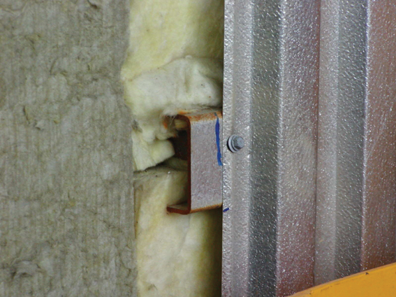 Figure 5
Secondary air duct with fiberglass insulation.
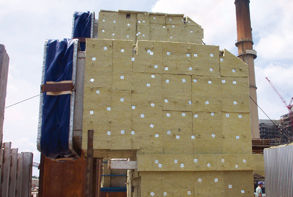 Figure 6
Mineral fiber Class 4 board used on a 1,000 F bypass flue.
 Figure 7
A large insulation lagging project.
 Figure 8
Lagging not in contact with insulation, showing attachments.
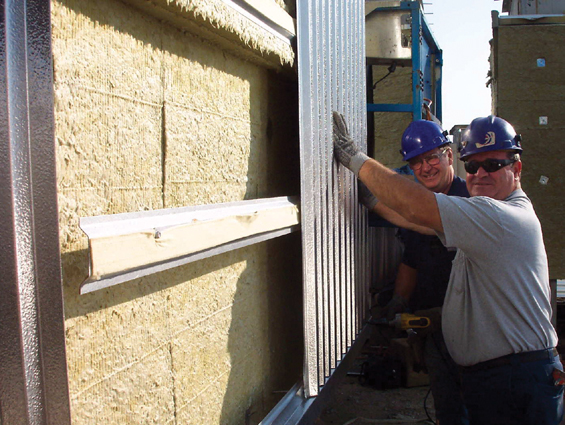 Figure 9
A lagging installation.