Insulation & Liquefied Natural Gas in Production and Storage
The recent surge in demand for energy, clean energy in particular, catalyzed a positive series of events for companies specializing in the manufacture, fabrication, and installation of high-performance industrial insulation systems. The sheer volume of insulation required to protect the high investment in these facilities has been inspiring.
The two biggest enemies of industrial insulation performance, moisture (liquid and vapor) and fire, are prominent in the engineering of liquefied natural gas (LNG) handling facilities. These issues need to be taken on separately with engineering of materials, but the good news is that the issues can be integrated for solutions.
It stands to reason that with most of these plants existing in hot and humid climates, the need for moisture vapor transmission (MVT) resistance is paramount. MVT can be excessive in these design conditions. The pipe or vessel may be at a continuous operating temperature of nearly -270°F (-168°C), and the ambient conditions are at 90°F (32°C) or more with humidity of 90 percent. In these conditions, the opportunity for moisture to be driven into the insulation is at its highest possible level. Since the natural moisture drive is from heat to cold, one can see how the material and application selections can make or break the system.
LNG is a mixture of low-molecular-weight hydrocarbons. The actual composition varies; however, LNG is primarily methane with ethane, propane, butane, and nitrogen present as well. Obviously, there is significant fire potential with LNG. The risk of fire can be reduced by proper material and application selection. Often, there are fire credentials critical to evaluating whether an insulation system should be considered for LNG service. These may include but are not necessarily limited to the National Fire Protection Agency (NFPA), the Coast Guard Approval (critical near or offshore), Underwriters Laboratories (UL), and Factory Mutual (FM).
Other key factors that affect material selection in LNG service include:
- Dimensional stability: Cold or cryogenic service temperatures can cause dimensional channel changes leading to warping of the insulation on the pipe, leaving gaps. In concert with high humidity, this can promote moisture entry that will promote ice buildup. This can be an expensive problem to repair.
- Compressive strength: Construction and maintenance of LNG pipe racks require tradesmen to work on and around the insulation. Physical damage is avoided by using insulation materials with high compressive strengths, absorbing the point loads and traffic. In addition, high compressive strengths are required for pipe supports, as the weight loads can damage insulation at those locations.
- Combustibility: Often fire protection is an additional consideration for the system. This requires the use of fire-rated materials, usually including stainless steel jacket and banding. This information is critical to the selection of the proper materials.
- Accessories selection: Selecting accessory materials that compliment the insulation is also critical. Because this application is critical and highly costly, the selection of proper accessories cannot be done in haste. Lab data is simply not enough. Extensive testing and proven performance history with the specified insulation are highly recommended.
- Insulation fabricator selection: Attention to detail in fabricating insulation for cold and cryogenic work should never be understated. Paying close attention to dimensions, specifically minimizing through-fabrication joints (joints perpendicular to the pipe that pass through the entire thickness of the pipe insulation segment) and 100 percent sealing of those joints will contribute to a successful project. It is suggested that a fabricator demonstrate the proper experience with cold and especially cryogenic work before an order is placed with them. As these projects tend to be very large in scope, the fabricator’s capacity for sourcing materials and converting those materials into quality insulation systems is an important consideration as well.
- Contractor selection: There are highly competent contractors familiar with the critical cold and cryogenic insulation techniques. These companies are staffed and managed around performance in critical end uses, of which LNG is certainly one. The bid list may not be as large as one would like, but competence should win the day with LNG candidates. Historical profiles and accessible reference lists should be the minimum for pre-qualifying an LNG insulation contractor. Financial stability is equally as important, as the contractor should have the ability to sustain the financial demands of a large, intensive project with high levels of labor and material costs.
Once the above factors have been addressed, the chances for successful installation are much better. Of course, there is no substitute for a good specification in which these factors are considered and a good on-site construction management team. When all these factors are in place and in practice, success is only a few months of construction away.
Where To Insulate an LNG Facility
The areas of insulation in LNG storage facilities include the containment tanks (sidewalls and bases) and the piping. Containment tanks are typically constructed by firms specializing in tank design. LNG containment tanks are usually double-walled construction, full containment tanks (see Figure 1), generally in the neighborhood of 180 feet high and 250 feet in diameter. The actual footprint varies with seismic activity as well as other considerations. The sidewalls of LNG containment tanks are usually insulated with a combination of loose-fill perlite and fiber glass blankets. The tank roof typically has a floating component insulated with closed cell foam. The tank base is usually insulated with multiple layers of high-density cellular glass. The details of the base and sidewall construction vary with the overall tank design. Two examples are illustrated in Figures 1 and 2. Figure 1 represents typical construction on a low tank with a wide footprint. Figure 2 represents a detail that might be used on a high tank with a narrower footprint.
Note that the sketches only outline the general principle of the connection between bottom and wall insulation. The design engineer should prepare in each case the appropriate drawing.
An LNG storage facility can have over 30,000 linear feet of cryogenic piping that requires insulation. These lines range in size, but typical sizes for primary unloading lines are 12-, 18-, 20-, and 24-inch diameters. The first step in the design of an insulation system for LNG piping is choosing the type of insulation. The associated piping on LNG projects should be insulated with a closed cell foam insulation. Polyisocyanurate insulation and cellular glass insulation are the predominant insulation types used in these applications. Low permeability is a key insulation property for this and all below-ambient services. The use of 0 perm closed cell insulation with joints sealed creates an impermeable insulation system. The insulation system itself becomes the primary vapor retarder.
Proper Thicknesses for LNG
The next step in the design is to determine the required insulation thickness for the system. The insulation thickness is determined through calculations based on the particular and unique environmental and operating conditions for the piping system being insulated. Engineers on LNG projects use two criteria for selecting the thickness on the various size lines. The first design thickness criterion is to limit heat gain to between 8 to 12 Btu/hr ft2 (22 to 32 kcal/hr m2). The second design thickness criterion is to limit condensation. Responsible engineering will result in selection of the greater of the two thicknesses that result from running both calculations. Often, this is where value-engineering and cost-cutting measures get implemented. Between the design and actual installation, often the owner will select the lowest insulation thickness. It is important at this stage that all parties are aware of the potential problems that could occur if this type of cost-cutting measure is implemented. Thickness calculations should be made using data points provided by the insulation manufacturer, especially because of the costs associated with either too much or inadequate thicknesses.
Pipe insulation for LNG systems is applied in multiple layers. Typically, inner layers of insulation are applied “dry” (without joint sealant); the outermost layer is applied with all joints sealed. All joints in successive layers are staggered from those of the first layer. A secondary vapor retarder is installed over the insulation, and metal jacketing is usually applied over all to complete the system. The type of insulation system design typical of cryogenic services is shown in Figure 3.
Given the large difference between the ambient and operating temperatures, coupled with the long runs of piping, contraction joints are usually installed in the insulation system. The typical contraction joint is designed to accommodate up to 1 inch (25mm) of contraction. These joints are located at intervals along the pipe that will limit the total contraction per joint to that amount. The specific contraction of the piping system will depend on the pipe material. For example, the thermal contraction of carbon steel will be significantly less than that of austenitic stainless steel. The contraction joint is constructed in a step pattern as shown in Figures 4 and 5. Contraction joint spacing is recommended every 100 feet of uninterrupted straight run piping, provided the contraction criteria above can be met within that spacing. This is typical for carbon, intermediate alloy, and straight chromium stainless steel.
A joint sealant is used between the outer two layers of insulation to provide a slip plane. A 0.062-inch (1.6 mm) solid neoprene vapor barrier sheet is wrapped over the contraction joint. This is sealed with joint sealant, then banded with stainless steel bands.
Critical Keys for LNG Systems
The key point to remember in LNG and other cryogenic applications is to start with an insulation product with low permeability. As stated above, additional considerations include dimensional stability, compressive strength, and combustibility of the insulation material. Compatibility of accessory products is also important for long-term system performance.
Finally, proper and timely communication among the manufacturer, contractor, fabricator, and end user is paramount to ensure a project’s successful completion. With high-profile projects like an LNG plant (production facility or receiving terminal), there is little margin for error, and the stakes are high.
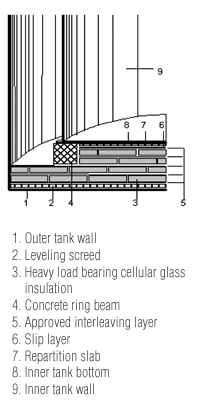 Figure 1
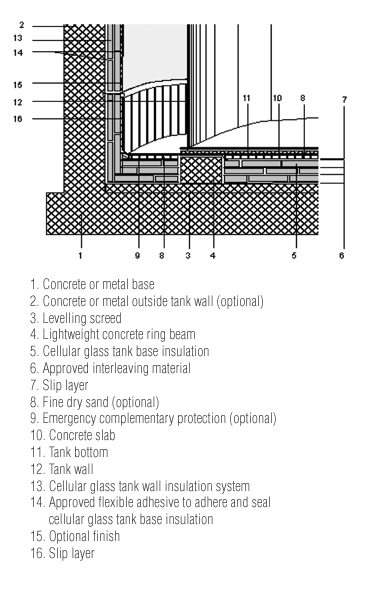 Figure 2
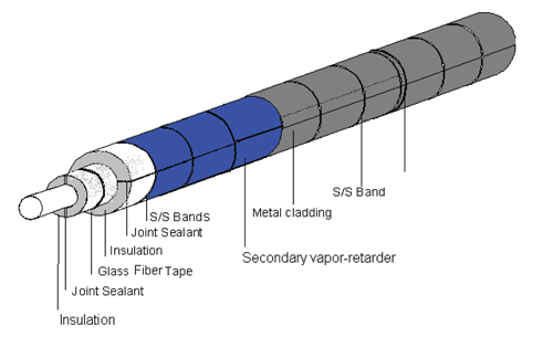 Figure 3
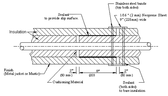 Figure 4
Two Layer Expansion/Contraction Joint
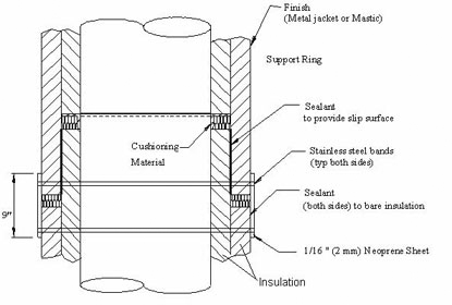 Figure 5
Vertical Contraction Joint