Maintaining Insulation Integrity at Pipe Support Locations in Commercial Buildings

Chad Rebholz

Chad Rebholz is a Certified Insulation Energy Appraiser and Technical Sales Representative for Buckaroos, Inc. (www.buckaroos.com), a fabricator of insulated pipe support systems. He has 12 years’ combined experience in mechanical piping and insulation with expertise in support methods for insulated piping. He can be reached at chadr@buckaroos.com.

August 1, 2017

Design engineers have utilized various methods to ensure the integrity of pipe insulation systems at pipe-support locations. The success of these methods depends heavily on the engineer’s foresight and understanding of the variables acting on the support location over the life of the system. In addition to the system requirements, optimal design and specification will factor in the following risks:

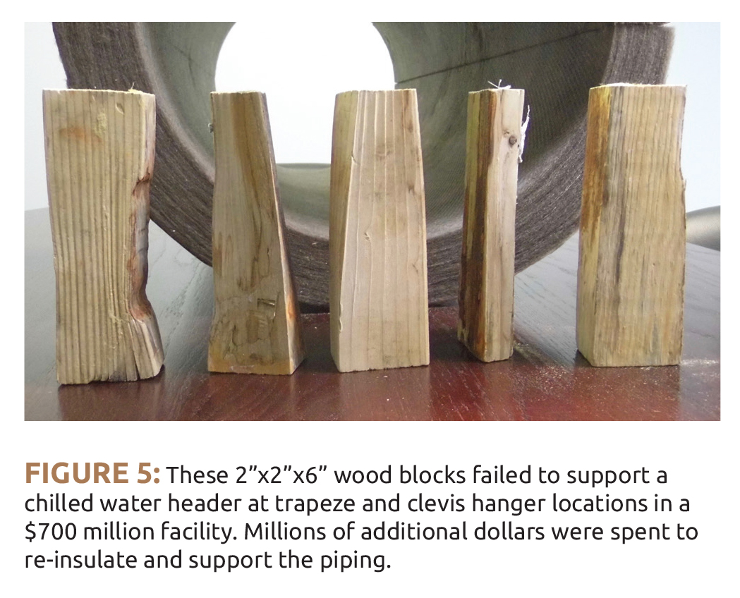
Risk of Poor Installation: Did the installer really use the rigid support that was specified at every hanger location? Were there wood blocks and were they properly aligned and centered over the hanger? How can this be assured upon inspection?
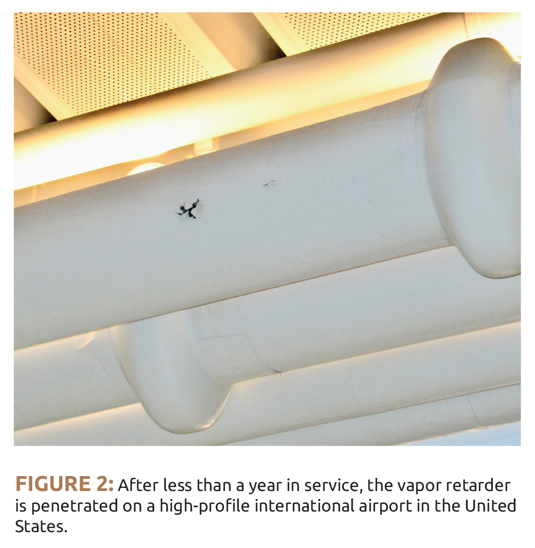
Inadequate Maintenance: What happens if the vapor retarder is damaged?
Dynamic Nature of Mechanical Systems: There is a degree of uncertainty regarding the extent to which linear expansion/contraction, water hammer, and other system movement and abuse will occur over the life of the system.

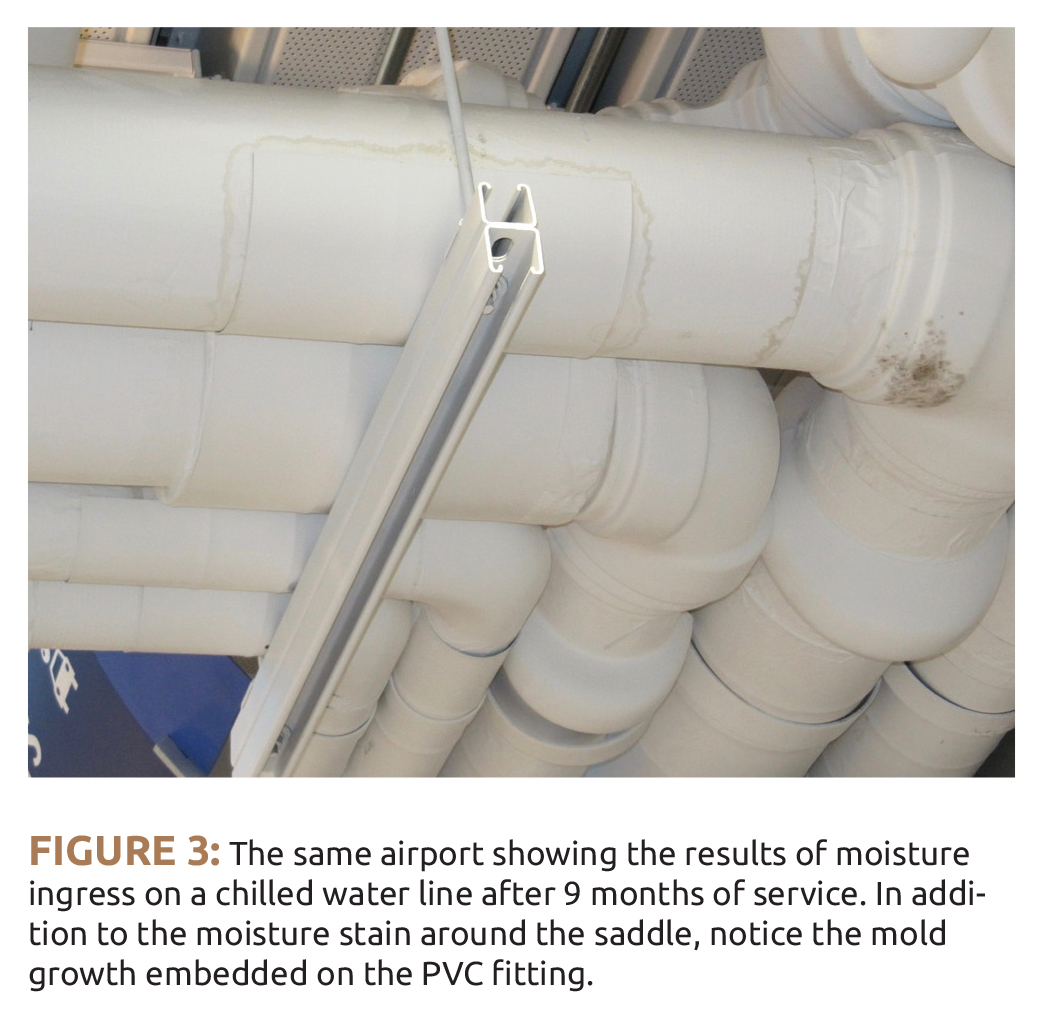
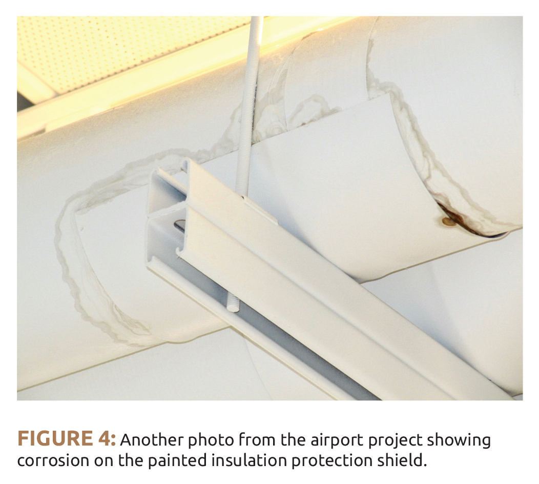
The selection of insulation material, vapor retarders, and adequate support are especially crucial for cold piping. Poorly supported systems are highly susceptible to damaged vapor retarders. When water vapor reaches the pipe surface and condensation occurs, fibrous or granular insulation and pipe meet their shared nemesis head on. The water-logged insulation system joins forces with the oxygen in the air to create a perfect recipe for corrosion under insulation (CUI) and mold formation.

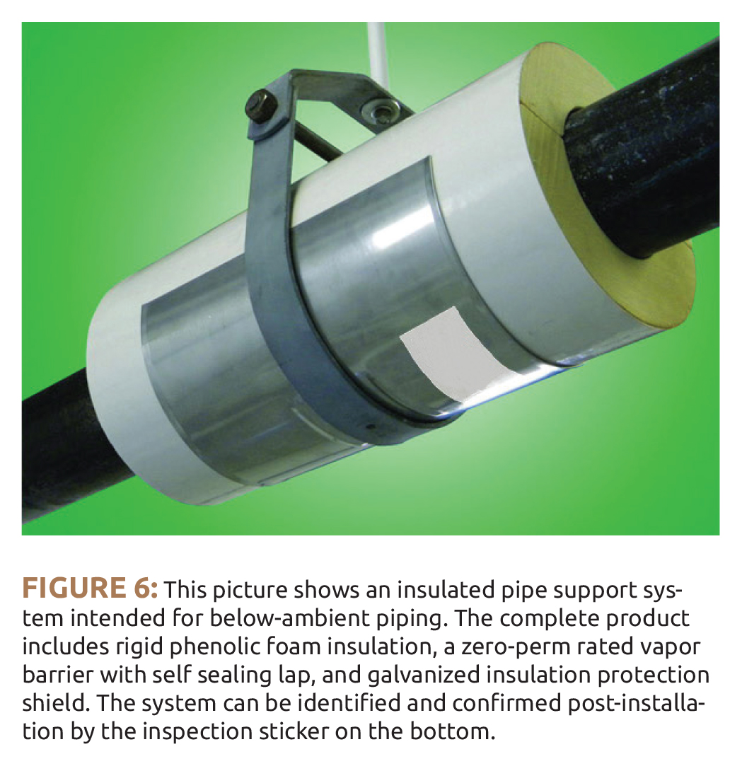
For these reasons, systems operating at below ambient temperatures can be insulated with a closed-cell insulation material as a secondary defense to the threat of a penetrated or damaged vapor retarder. Additionally, a low permeance vapor retarder meeting the industry standard of ≤0.02 perms provides added protection to any existing vapor retarder that is commonly pre-applied to fiber glass pipe covering.

The increased risk of mold and CUI in cold systems adds to the significance of detailed pipe support specifications. The strongest specifications usually involve different pipe support materials for cold and hot systems as well as special considerations for pipe resting on a flat surface as opposed to a clevis hanger. This article will provide insight for engineers to consider as they evaluate their options for supporting insulated piping.

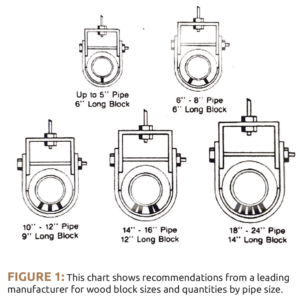
Wood Blocks and Saddles

The most commonly specified and traditional means of supporting and protecting insulated piping in many applications is with wood blocks and insulation protection shields (commonly referred to as saddles by insulators). This method offers the lowest material cost to accomplish the goal. However, it is often incorrectly specified and is not recommended by ASHRAE or the National Commercial & Industrial Insulation Standards manual (also known as the MICA Manual). There are some key reasons to take caution before moving forward with wood blocks and saddles:

  1. Wood burns, and it should not be specified when the design is subject to compliance with the latest update to the International Mechanical Code (2015) Section 602.2.1. It states that “materials within plenums shall be noncombustible or shall be listed and labeled as having a flame spread index of not more than 25 and a smoke-developed index of not more than 50 when tested in accordance with ASTM E84 or UL 723.”
  2. Unless inspection occurs during the installation, verification of correct sizes and quantities of wood blocks cannot be guaranteed upon visual inspection.
  3. Wood is naturally hygroscopic, which makes it a poor choice for systems operating at below-ambient temperatures. If and when the vapor protection is compromised, condensation will quickly be absorbed by the wood. Wood blocks, with their poor thermal conductivity, may cause condensation at their locations. At this point, the risk of mold formation and CUI is much greater.
  4. When wood blocks are used in conjunction with a flat resting surface (pipe rack, trapeze, strut, etc.), it is important to account for the increased point load compared to a clevis hanger, where weight can be better distributed across multiple blocks. The only support that can be considered load-bearing is the bottommost wood block when pipe is rested on a flat surface.


Small diameter piping may not be affected, but it is common to see large piping suspended by strut with bowed saddles. Performing point load calculations will help determine if an additional steel plate is necessary to add structural stability and help disburse the load between the galvanized saddle and the flat support surface.

High-Density Fiber Glass Blocks and Saddles

The fact that wood is combustible has driven many engineers to eliminate wood blocks as an option entirely. The next most cost-efficient support mechanism is high-density fiber glass blocks. Depending on the supplier, fiber glass blocks offer a K-factor of approximately .30, various compressive resistances, and can perform well at higher operating temperatures.

Most importantly, fiber glass blocks can be used in plenum spaces with a flame-spread and smoke-developed rating of 10/10 per ASTM E84. However, some of the downfalls associated with wood blocks still exist and should be noted:

  1. Unless inspection occurs during the installation, verification of correct sizes and quantities of fiber glass blocks cannot be guaranteed by visual inspection.
  2. Though the binding agent offers some minimal resistance to liquid water ingress, fibrous insulation material still has open air space between fibers and offers little resistance to water vapor. Water and moisture retention can occur, resulting in loss of insulating ability, mold, or CUI.
  3. Leading manufacturers have charts similar to the previous example for wood blocks that indicate proper lengths and quantity requirements per pipe size. Visual verification of proper install remains a concern for inspectors.
  4. Inspection must occur during installation. It is impossible to tell how many fiber glass blocks were installed at any given support location upon completion. Lack of visual verification also prohibits verification that the supports are composed of high density fiber glass as opposed to wood.
  5. The installation of block-style supports requires the installer to carefully cut and remove fiber glass material from the inside of a clam-shell section of fiber glass pipe cover. Most often, the fiber glass pipe covering is pre-jacketed with an all service jacket (ASJ) that serves as the vapor retarder. It takes precision with a filet knife in order to preserve the integrity of the jacket without penetration. Even the most skilled insulator is bound to cut through the ASJ when this process is repeated for hundreds of support locations on a large project.

Rigid Insulation Insert and Saddles

As previously stated, closed-cell insulation is often preferred for below-ambient piping. Three prime candidates to meet this need are cellular glass, phenolic foam, and polyisocyanurate insulation—all of which have the added benefit of a rigid structure. At high enough densities, these 3 materials will provide sufficient compressive strength to serve as a support mechanism. When engineers use the term “rigid insulation insert” in specifications, one hopes performance characteristics of the insulation, jacket, and saddle will be laid out with the option for the field assembly of the components.

While not rigid, some form of elastomeric insulation is another common closed-cell solution. The “insert” material of choice might be one of the 3 aforementioned rigid insulations. Additionally, some elastomeric insulation manufacturers have developed proprietary insulated pipe support systems.

Most hot water piping systems also operate at temperatures suitable for cellular glass, phenolic foam, or polyisocyanurate insulations. However, calcium silicate is most common due to its superior compressive strength.

The practice of specifying a rigid insulation material to support piping is becoming more popular across the country. It translates to a higher level of confidence in the integrity of the insulation system at pipe support locations. The consistent compressive strength and load distribution of such materials reduces the risks associated with poorly installed blocks.

Rigid insulation inserts can be fabricated in the field or by a dedicated insulation fabricator as determined by the specification or the installing contractor. Material cost compared to blocks will be higher either way, but the growth in demand for such products suggests that the added value outweighs the higher material cost. Specifications for rigid insulation inserts and saddles must include more detail than block-style specifications in order to truly realize the added value. Here are some tips to keep in mind:

  1. Be specific about length of insert material, type of vapor retarder, length and gauge of saddle per size, allowance for circumferential tape enclosure, etc. Otherwise, it will result in multiple requests for information.
  2. Clearly define that the insulation inserts (with jacket and saddle) should be installed when setting the pipe elevation. If this is not defined, there is a risk that the insulation contractor will unintentionally modify the elevations when lowering and raising clevis hangers during support installation. Depending on the circumstances, the efficiency of the mechanical system can be greatly lessened.
  3. Ensure that the insulation material is suitable for the demands of the system and code requirements. Only closed-cell insulation should be allowed in below-ambient conditions. Also evaluate the flame and smoke ratings, which will differ for some materials depending on the insulation thickness.
  4. Load distribution calculations are the only tried and true way to determine if an additional plate is required below the saddle.
  5. Site visits are necessary to verify that the specified materials are being installed. Visual inspection of supports, especially after the insulation system installation has been completed, does not confirm compliance with specification.

Insulated Pipe Support Systems

This category encompasses a system approach to supporting insulated piping. In other words, each system ships as a finished product that includes rigid insulation material, vapor retarder, and saddle. Insulated pipe support systems are unique to the application for which they are intended. Each is defined by a detailed specification in the form of
a technical data sheet. Usually, there is a brand name associated with the line of insulated pipe support systems.

The systems approach boasts all of the benefits of the rigid insulation insert and saddle combination with added benefits.

  1. Specification compliance can be visually verified upon inspection by way of the manufacturer’s sticker on the bottom of the support.
  2. Specifying engineers can confidently select and rely on insulated support systems based on manufacturer recommendations. Manufacturers will naturally stand behind their products and many will provide installer training if desired.
  3. Choosing insulated pipe support systems over any field-fabricated support method shifts the variable cost of labor to the fixed cost of materials, thus reducing the overall risk exposure. Decreased labor risk leads to more surety in the project timeline, less chance of job site injuries, and less chance for installer error.

Dedicating additional time and effort to pipe support specifications is a practice that will vastly improve the performance of an overall pipe insulation system. Like anything else, the system is only as good as its weakest link. Even small areas of damaged insulation can translate to substantial additional energy costs over time. Water-saturated insulation can be worse than having no insulation at all, so it is important to choose materials carefully and install them properly.


Copyright Statement

This article was published in the August 2017 issue of Insulation Outlook magazine. Copyright © 2017 National Insulation Association. All rights reserved. The contents of this website and Insulation Outlook magazine may not be reproduced in any means, in whole or in part, without the prior written permission of the publisher and NIA. Any unauthorized duplication is strictly prohibited and would violate NIA’s copyright and may violate other copyright agreements that NIA has with authors and partners. Contact publisher@insulation.org to reprint or reproduce this content.


Related Articles

An Overview of the Structure of Insulated Pipe Supports

When people ask me what I do for a living my response is, “Go inside any commercial building or garage and look up.” It may not be glamorous, but it is extremely important. The primary reason for insulated pipe supports is to support the weight of the pipe. The secondary reason is to provide continuous

Read Article

Looking at Pre-Insulated Pipe Supports

One of the most significant concerns for any plant engineer is how to save energy and operating costs. One way is by utilizing the appropriate pipe support components within the plant’s piping system. Choosing the wrong type of pipe supports can lead to extremely high costs, heat loss, corrosion under insulation (CUI), and a host

Read Article

Pipe Insulation Supports: The Key to a Complete System

Choosing the correct support system is integral to the long-term performance of a new pipe insulation project.

Read Article

Pipe Insulation Support Saddles

Proper mechanical support is essential for a smooth ride.

Read Article