Multifunctional Thermal and Acoustical Solutions
As in all industrial facilities, when planning the construction of a new oil or gas complex, the requirements for both thermal insulation and noise control must be fulfilled. In most cases these 2 areas are still handled separately by the respective design teams. If these 2 teams operate without any coordination, it can lead to significant inefficiencies in design and result in insulation systems that are thicker or do not fulfill all system requirements. Flexible foam insulation is one option that can help meet both the thermal and acoustical requirements for a number of oil and gas applications. While flexible elastomeric foams have grown in popularity to prevent corrosion under insulation (CUI) for the oil and gas industry, this article will focus primarily on its acoustical abilities.

History
Flexible foam insulation typically refers to elastomer-based materials consisting predominantly of synthetic rubber. Flexible elastomeric foams (FEFs) were introduced in the 1950s, marking an industry transition from the previous common practice of installing heavy, rigid insulation layers. The use of elastomeric insulation grew quickly, and with the introduction of continuous sheet products, preformed tubular sections, and self-adhesive tubes and sheets, the number of application areas continued to expand.
FEFs can be installed on all kinds of equipment, from residential service-water piping and ducting to large commercial chillers and ventilation systems. Closed cell FEFs not only protect HVAC/refrigeration components against thermal losses and condensation, they are also used on mechanical systems in industrial, pharmaceutical, and oil and gas applications ranging -292°F to 302°F (-180°C to 150°C). In recent years, the demand for insulation with multifunctional capabilities has increased dramatically, and flexible foams have proven to be one of the suitable options for addressing numerous new challenges.
Installation Specifics
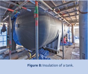
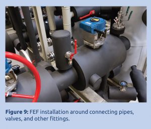
FEF is flexible, which may reduce complexity during installation on pipework, bends, fittings, equipment, and vessels. Its flexibility also allows it to withstand vibration and movement without degrading. While installing foam insulation does require the knowledge of an experienced insulation contractor, it can be installed without special tools or equipment.
Time is an extremely critical factor in any new-build construction in the oil and gas industry. The contractually-defined milestones for the completion of a large facility, such as a liquid natural gas (LNG) liquefaction plant or petrochemical complex, can only be achieved if the time and cost estimates for the individual work packages are satisfied at each stage of the project. In the case of insulation, the speed at which the materials can be installed is likely to play a deciding role in the specification and selection of particular insulation types.
FEF insulation materials may be somewhat more expensive than traditional insulation materials. Savings can be achieved, however, with efficient installation around more complex fittings. Space and weight are also crucial factors in the design, construction, and maintenance of oil and gas facilities.
Effective Noise Control for a Safe Working Environment
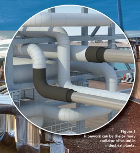
Employees are a facility’s most valuable asset, and their safety must be a priority. Acoustical insulation is of paramount importance in regard to personnel. Compressors, pumps, control, and relief valves generate significant noise levels, which are transmitted into the connecting pipework. Noise is often increased when gases and fluids flow under high pressure or velocity, and turbulence is generated in the vicinity of obstacles such as valves or orifice plates, or as a result of changes in flow direction. Among acoustic engineers, the general view is that noise from pipework can account for around half the total noise output (sound power) of a typical petrochemical or LNG liquefaction facility. According to an article published by the National Insulation Association (NIA), piping can be the primary radiator of sound in industrial plants.1
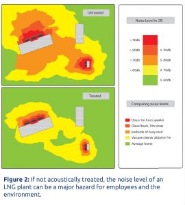
The excessive noise levels that can arise through unprotected or inadequately insulated installations are not just an annoyance for the employees; they are also a risk to their health. Noise-induced hearing loss is one of the most common occupational injuries. The risk of accidents in the workplace also rises due to noise—such as when warning sirens or alarms are not heard. Furthermore, noisy environments often lead to a drop in individual performance and a loss of concentration, resulting in mistakes and the subsequent risk of injury. Excessive industrial noise also causes disturbance to neighboring residential communities, as well as adversely affecting the behavior of local fauna (e.g., impacting breeding habits, etc.).
Noise mitigation begins with the right choice of equipment, materials, and a well-planned layout to ensure minimal noise generation. Existing site measurements and past engineering experience, coupled with computer modeling techniques, are often employed to establish best practice for quieter plant design. When all appropriate measures to reduce noise at the source have been explored, insulating pipes is the most effective method of attenuating noise from process lines. Sound absorption is one of the key measures required to minimize noise.
Traditional soundproofing or acoustic insulation for industrial applications has often consisted of mineral wool, plastic foam, polyester, or fibrous material with a cladding (outer shell or jacket) made of aluminium, stainless, or galvanized steel sheets; loaded vinyl barriers; or metal jackets. The acoustic performance of these systems depends on the thickness and density of the materials. In cold or cryogenic processes, rigid, closed-cell insulation—such as polyisocyanurate or cellular glass—is often used to provide thermal protection and mineral wool insulation is layered on top for acoustical purposes.
Development of Elastomeric Noise Control Systems
FEFs have been used for many years in industrial noise control, especially in applications where fibrous materials are not suitable. There was a time when FEFs were considered unsuitable for sound control in industrial installation—until the acoustic insulation performance of FEFs began to be explored in the early 1990s. Extensive studies have demonstrated that FEF layers can be combined to achieve excellent vibro-acoustic insulation performance suitable for noise control on industrial process pipelines.2
In order to further enhance the acoustic performance of these systems, it was necessary to investigate methods for changing the structure of the materials to improve sound absorption properties. Elaborate research in cooperation with the University of Bradford (Great Britain) succeeded in developing a completely new FEF material with excellent sound-absorption capabilities.3 This was achieved by re-engineering the closed-cell elastomeric insulation material into an open-cell material with optimized micro-structure.
It is important to note, however, that when FEF is converted from closed to cell to open cell, the water transmission properties, both liquid and water vapor—as well as the thermal conductivity—are negatively impacted.
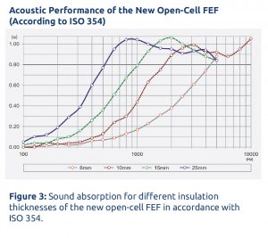
Figure 3 shows the sound absorption coefficient αs, measured according to ISO 354,4 for various material thicknesses. αs is defined as the ratio of the absorbed sound energy to the incident sound energy, where a value of 0 represents complete reflection and 1 complete absorption. Here it can be seen that at a thickness of 25 mm (1”) the values for the sound absorption coefficient are greater than 0.8 from a frequency of approximately 500 Hz onwards.
Requirements of ISO 15665
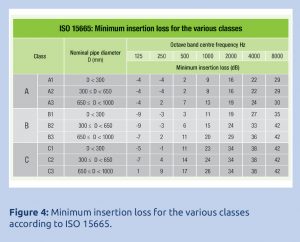
As stated earlier, significant noise is generated from pipework. The performance of acoustic insulation systems is measured by the international standard ISO 156655 “Acoustics—Acoustic insulation for pipes, valves and flanges.”6 Figure 4 shows the values required for the minimum insertion loss (or acoustic insertion loss) that the insulation configuration under evaluation must achieve in order to fulfill the classification criteria in the relevant octave band center frequency. The failure of a selected system to satisfy the criteria set for all octave bands results in that system either being classified to a lower grade or alternatively remaining unclassified. In order to account for changes in acoustic radiation efficiencies, the classification also makes a distinction depending on the pipe diameter.
Test Set Up
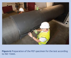
Details on the test set up and test procedure can be taken directly from ISO 15665 and are not provided in detail here. However, a short explanation of the test follows to aid understanding. Figure 6 shows the test set up, including the sound source. The pipe is 18’, 2 ½” (5,560 mm) long, has an outer diameter of 12¾” (323 mm), and a wall thickness of ¼” (6.3 mm). As the outer diameter is >300 mm (12”), the criteria of classes A2, B2, and C2 apply according to Figure 4.
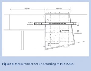
The insulation construction is mounted on the pipe inside the reverberation room, ensuring that the pipes are carefully sealed with mastic in the 2 penetration areas. The measurements are carried out on the uninsulated and insulated pipe in each case. The mean sound pressure level is measured using a microphone attached to a rotating boom in accordance with ISO 3741 in the frequency range of 100 Hz to 10 kHz.
The insertion loss for each frequency range is calculated using the following formula:
Dw = Lb – Lc – (Lbr – Lcr)
Where:
Dw is the insertion loss (dB)
Lb is the mean one-third octave sound pressure level of the uninsulated pipe (dB)
Lc is the mean one-third octave sound pressure level of the insulated pipe (dB)
Lbr is the mean one-third octave sound pressure level in the room for comparison sound source of the uninsulated pipe (dB)
Lcr is the mean one-third octave sound pressure level in the room for comparison sound source of the insulated pipe (dB)
The insertion loss for the octave band frequency can be calculated from the one-third octave band frequency as follows:
Where:
Dwi is the insertion loss per one-third octave band of the corresponding octave band.
According to the requirements of ISO 15665, different multi-layer constructions were developed. The standard distinguishes between classes A, B, and C, and correspondingly, 3 different insulation systems are offered. In most cases, the new FEF systems greatly exceed the reductions required in the individual classes of the standard. In addition to the classifications stipulated in ISO 15665, a thermal-acoustic system D was specifically developed to meet Class D of Shell Specification DEP No. 31.46.00.31.7
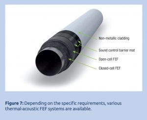
Modular Thermal-Acoustic FEF System Components
The thermal-acoustic FEF systems consist of the following components:
• A closed microcell FEF with low thermal conductivity and some resistance to water-vapor transmission, which, when paired with an appropriate vapor retarder, may provide installations with long-term, reliable protection against water ingress and energy losses;
• An open-cell acoustic foam with excellent sound absorption properties at lower insulation thicknesses;
• Sound-control barrier layers made of vinyl and bitumen respectively, which greatly reduce the transmission of airborne sound from installations and further enhance the acoustic performance;
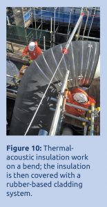
• A rubber-based covering system, which protects against UV, saltwater wash-over, mechanical impact, and provides installations with effective mitigation of CUI;
• A fiber-reinforced polymer (FRP) covering with excellent mechanical strength and potential mitigation of CUI; and
• Non-flammable jacketing systems made of stainless steel, galvanized steel sheets, aluminium, or aluminium zinc.
These composite multifunctional systems not only fulfill acoustic requirements, but they also provide stable thermal insulation performance, condensation control, and personal protection. They satisfy tough fire performance requirements and international approvals such as DNV and BV, cope with harsh environmental conditions (including adverse weather, saltwater spray, UV exposure, etc.), and they may provide some protection against CUI.
One of the unique aspects of these FEF-based thermal acoustic insulation systems is that they are built up modularly. FEF systems allow the potential for both thermal insulation and noise control to be satisfied in one system. The construction of the system is specified according to the individual requirements of the plant to be insulated. Additionally, the material is flexible and can take a great deal of vibration and movement without degrading.
Conclusions
Developments in FEF technology are allowing owners and operators of LNG and other oil and gas facilities to satisfy often conflicting health and safety requirements with insulation systems that offer improved acoustic performance combined with a reduced risk of CUI.
These new multi-layer constructions conform to the relevant classification criteria of ISO 15665 for the acoustic insulation of pipes, valves, and flanges. In most cases, they greatly exceed the noise level reductions required.
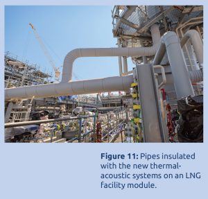
While FEFs were considered niche products in the oil and gas industry in the 1990s, these materials are now established in the market and are regularly used. FEFs are specified and selected on an ever-growing number of major oil and gas projects, most recently for the Australian Greater Gorgon and the Ichthys LNG facilities. With the target of extracting 8.4 million tons of LNG per annum, the Ichthys field will be the second largest oil and gas facility in Australia’s history and is currently one of the most significant offshore ventures worldwide. So far around 400,000 m2 of thermal and acoustic insulation materials and coverings have been installed on the various modular construction elements of the LNG facility and, for the first time in an oil and gas project of this scale, up to 40% of this material will consist of elastomeric insulation materials. Given their ability to meet thermal, acoustic, and combined thermal-acoustic insulation needs, they offer a good option for many industrial applications.
Endnotes
1. Scott Miller, “Acoustical Lagging Systems—New Information on Noise Reduction,” Insulation Outlook April 2001, www.insulation.org/io/articles/acoustical-lagging-systems-new-information-on-noise-reduction.
2. Mark Swift and and Jürgen Weidinger, “Flexible Dämmsysteme in der Öl- und Gasindustrie.” (“Flexible insulation systems in the oil and gas industry,”) GAK 4/2011; pages 224–227.
Mark Swift, “A novel laboratory method to measure the efficiency of acoustic insulation for pipes,” Presentation at the inter.noise 2012, New York, New York, USA.
3. Mark Swift and Kirill V. Horoshenkov, “Thermo-acoustic properties of elastomeric pipeline insulation,” presentation at the November 2009 Noise and Vibration: Emerging Methods. Oxford, UK.
4. Similar to the ASTM C423 method.
5. ISO 15665: Acoustics, Acoustic insulation for pipes valves and flanges. International Organisation for Standardisation. 2003.
6. Similar to the ASTM E1222 method “Standard Test Method for Laboratory Measurement of the Insertion Loss of Pipe Lagging Systems”
7. Hubert Helms, “Neue Dämmstoffe als Schallschutzlösungen.” (“New insulation materials as noise control solutions”), Isoliertechnik 4/2007, pages 38–44.
All photos and figures in this article are courtesy of Armacell unless otherwise noted.
Copyright Statement
This article was published in the June 2017 issue of Insulation Outlook magazine. Copyright © 2017 National Insulation Association. All rights reserved. The contents of this website and Insulation Outlook magazine may not be reproduced in any means, in whole or in part, without the prior written permission of the publisher and NIA. Any unauthorized duplication is strictly prohibited and would violate NIA’s copyright and may violate other copyright agreements that NIA has with authors and partners. Contact publisher@insulation.org to reprint or reproduce this content.