NDT Inspection of Insulated Vessels and Piping for Interior Corrosion and CUI
Non-destructive testing (NDT) inspection of insulated vessels and piping has long been a major challenge. Conventional techniques such as profile radiography and ultrasonics often are impractical or cost-prohibitive because of limited productivity, insulation removal cost or temperature restraints. This article presents an overview of two technologies that are designed for online corrosion inspection of insulated components: profiler portable real time radiography, and pulsed eddy current. It addresses the practical applications, typical productivity, strengths and limitations of each technology.
The need for improved online inspection of insulated vessels and piping has existed for decades. The primary objective of each owner/user facility is to operate as profitably and safely as possible. Many inspection-related issues factor into this goal. Is it necessary to shut down the plant or a portion of the plant to perform a specific inspection? What is the collateral cost associated with performing an inspection (i.e., scaffolding erection, insulation removal, process modifications caused by heat loss)? Additionally, if the insulation contains asbestos, an abatement cost will be incurred. Finally, and perhaps more importantly, what are the risks and ramifications if the inspections are deferred?
This article discusses real time radiography technology (RTRT) and pulsed eddy current technology. These technologies can provide new options/resolutions for some of the above issues.
Real Time Radiography
The RTRT unit is a portable, real time, non-contact density measurement system that provides quantitative wall thickness information using gamma absorption from the low-level exempt isotope Gadolinium 153 (Gd-153). The unit is designed to quickly examine insulated piping for blockage, internal corrosion and corrosion under insulation (CUI). The output of the collimated Gd-153 source is directed to a special scintillator. The
scintillator electronics contain the equivalent of a low-level X-ray camera. In turn, the scintillator is coupled to a photomultiplier tube whose electronics are matched to the scintillator output. The RTRT unit produces an output signal that is sent to the computer. The computer presents a real time digital strip chart of the component thickness. Figure 1 is a schematic representation of the component parts.
The high efficiency of the RTRT process enables a low-strength source to penetrate much denser materials than can conventional RT film. The unit can obtain double-wall thickness measurements of fluid-filled piping up to 13 inches (33 cm) in diameter with nominal 4.5-inch (11.4-cm) wall (pipe wall plus insulation). Larger pipe diameters can be inspected if they are not fluid-filled. The RTRT unit provides a repeatable measurement accuracy of 2 percent of the density.* The equipment can be applied to a wide range of materials including carbon steel, stainless steel, plastic and concrete. As a rule of thumb, the unit can penetrate the equivalent of 1.25 inches (3.2 cm) of steel. The density of water is approximately one-tenth that of steel. The units are equipped with one curie Gd-153 source having a half-life of 243 days.
Calibration
Calibrations are performed by indicating the representative thickness of insulation and water path between the source and detector. Additionally, various thickness of the component wall material (generally steel plate samples) are used to simulate the anticipated range of the thickness to be tested. Through this process, a linear thickness range is established on the computer screen for measurement during the inspection.
The thickness output reflects only the pipe thickness and not the collective insulation and water thickness. Because some variations occur from nonuniformity of the insulation and water path, one should not expect the reported thickness reading obtained by the RTRT unit to have the same accuracy as conventional ultrasonics. Instead, consider the reading an indicator of relative thickness change requiring further interrogation with alternative techniques in the area of concern.
Examination
Examinations are performed with a two-man crew. One person manipulates the measuring unit while the second person monitors the computer display. The system is battery operated, so no external alternating current (AC) power is required. All examination data are displayed in real-time; however, the digital data output can be stored for future evaluation and for reporting documentation.
The unit straddles the pipe and is manually moved down its length. The unit can then be rotated 90 degrees and the exam repeated if four-quadrant interrogation is desired. For two-quadrant examinations, it is reasonable to expect a production rate of 1,000 to 1,200 linear feet (305 to 366 m) of pipe per shift, assuming convenient access to the pipe is available. Pipe rack environments generally yield inspection production rates of 400 to 600 linear feet (122 to 183 m) of pipe per shift.
Because the RTRT unit measures all density between the source and detector, the output displays the thickness of both pipe walls. When a change in thickness is observed, however, a scan across the pipe axis reveals which side of the pipe is responsible for the change of thickness (i.e., area of corrosion). The same technique can be applied on jacketed piping to determine which azimuth of which pipe (inside or outside pipe) contains wall loss. Figures 2 and 3 show typical output displays.
Pulsed Eddy Current
The second technology to be addressed uses the principle of pulsed eddy current. This inspection system is used to perform online wall thickness measurements on ferrous pipes and vessels without removal of the thermal insulation.
A probe containing a transmitter and receiver coil is placed on top of the thermal insulation. The transmitter coil is activated and a magnetic field is established in the steel being inspected. The current is then switched off and the magnetic field is terminated, causing eddy currents to be induced into the near surface of the pipe wall. As the eddy currents diffuse through the wall, they decay at a known rate. When they reach the far side of the wall, the eddy currents decay at a much higher rate. The receiving coil detects this change, and the system calculates the distance to the inside diameter and the wall thickness.* The measurement is an average of the remaining wall over the area of the footprint of the probe.
The footprint size can vary because of several factors such as liftoff (insulation thickness), probe selection and insulation sheathing material. Also, embedding chicken wire in the insulation typically increases the footprint size by about 40 percent. As a result, the system is much better suited for measuring generalized corrosion, erosion and CUI rather than very localized pitting; a very localized pit will not have a significant affect on the average thickness under the entire area of the footprint.
Calibration
Calibration typically is performed on the structure to be inspected. First, a reference point is established. All subsequent readings can be compared to the reference point. If the structure is fully insulated (i.e., no reference ultrasonic test [UT] reading can be obtained) and the thickness at any specific location is not known, then the reference point is assigned a thickness of 100 percent. All subsequent readings are presented as a percentage relative to the reference point. The system can display the readings in inches at any point afterward if a thickness reading is provided at one of the measurement points. It may be necessary to establish more than one reference point if any key variables substantially change across the area of the structure.
Key variables include conductivity and permeability. They are affected by component temperature and material composition, including changes caused by heat treatment of the component. The inspection procedure provides all necessary guidance for system configuration as well as probe selection required during the calibration.
Examination
Measurements are obtained in an X-Y grid pattern. With favorable field conditions, one can obtain up to 1,000 readings per shift. The cycle time between two readings typically is 3 to 10 seconds.* The unit is capable of inspecting components online within a temperature range from —150 to 900 F (—101 to 482 C). Wet or irregular insulation does not impede the inspection. The pulsed eddy current system also can be utilized when conventional UT is impractical because rough, encrusted or coated surfaces are present. Components up to 2.5 inches (6.4 cm) in thickness (minimum thickness of 0.12 inches [0.3 cm]) can be inspected with insulation up to 6 inches (15.2 cm) thick. To avoid the effects of curvature, pipe diameters of less than 3 inches. (7.6 cm) cannot be inspected with this system. Battery operated and portable, the system requires no external AC power. Ferrous attachments such as branch connections, nozzles, etc., cause interference in the readings. As a result, measurements are not reliable within close proximity of such attachments (2 times the insulation thickness). The system software allows for onsite hardcopy reporting of inspection results.
Figure 4 shows the typical field use of the pulsed eddy current technique. Figure 5 shows a typical display.
Conclusions
Effective screening and monitoring of insulated piping and vessels can be of great value in overall facility inspection and maintenance programs. Evaluate key issues such as cost, productivity, disruption of plant operations, and minimization of plant shutdowns when implementing inspection programs.
The two technologies discussed in this article provide options where critical information can be obtained online on vessels and piping with minimal auxiliary cost (insulation removal, etc.). As with all technologies, each has its strengths and limitations. It is very important that end-user expectations are compatible with the capabilities of the technology so that optimum results can be obtained.
Recognize that the RTRT is a high-production screening tool allowing for inspection of long runs of insulated pipe at lower cost than conventional techniques. After identifying abnormalities, perform further interrogation in the area of interest with other NDT methods.
One of the strongest attributes of the pulsed eddy current system is the fact that large-diameter vessels, with up to 2.5-inch thickness, can be inspected online without the need for insulation removal.
* References pulled from proceedings of the 15th World Conference on Nondestructive Testing, 2000, and the 7th European Conference on Non-destructive Testing (ECNDT), 1998.
Reproduced with permission from NACE International, Houston, TX. All rights reserved. Published in the April 2004 issue of Materials Performance. NACE International 2004.
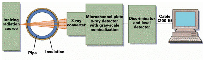 Figure 1
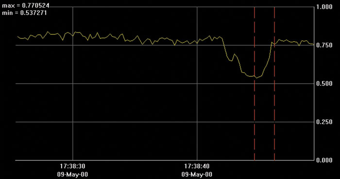 Figure 2
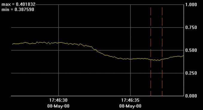 Figure 3
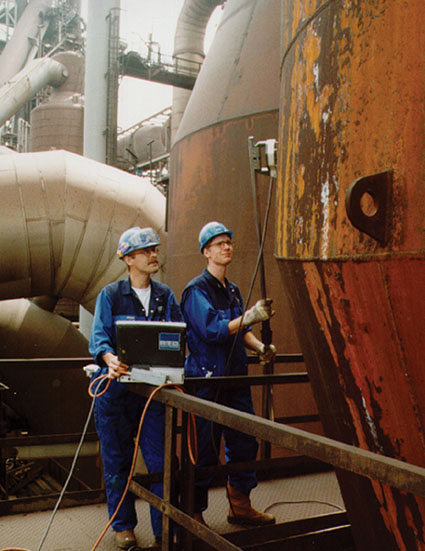 Figure 4
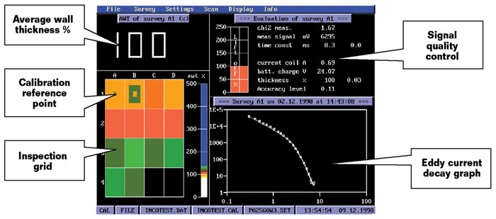 Figure 5