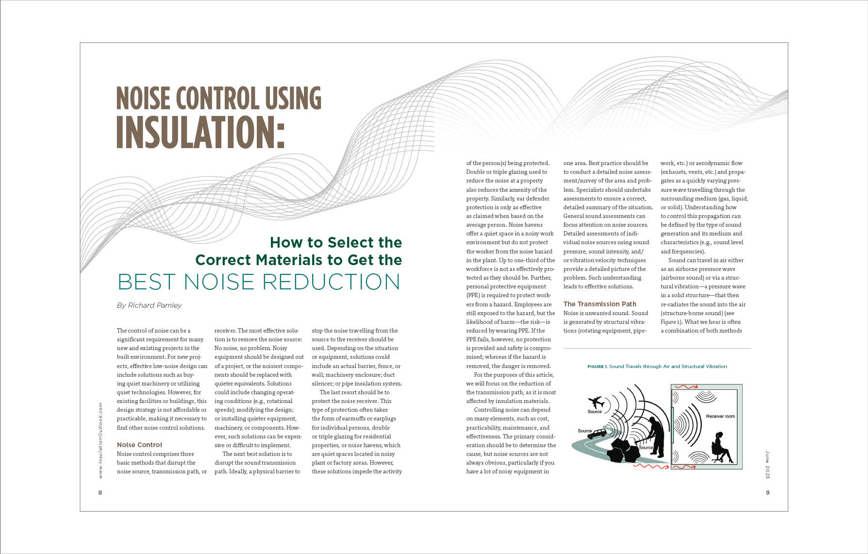
Noise Control Using Insulation: How to Select the Correct Materials to Get the Best Noise Reduction
The control of noise can be a significant requirement for many new and existing projects in the built environment. For new projects, effective low-noise design can include solutions such as buying quiet machinery or utilizing quiet technologies. However, for existing facilities or buildings, this design strategy is not affordable or practicable, making it necessary to find other noise control solutions.
Noise Control
Noise control comprises three basic methods that disrupt the noise source, transmission path, or receiver. The most effective solution is to remove the noise source: No noise, no problem. Noisy equipment should be designed out of a project, or the noisiest components should be replaced with quieter equivalents. Solutions could include changing operating conditions (e.g., rotational speeds); modifying the design; or installing quieter equipment, machinery, or components. However, such solutions can be expensive or difficult to implement.
The next best solution is to disrupt the sound transmission path. Ideally, a physical barrier to stop the noise travelling from the source to the receiver should be used. Depending on the situation or equipment, solutions could include an actual barrier, fence, or wall; machinery enclosure; duct silencer; or pipe insulation system.
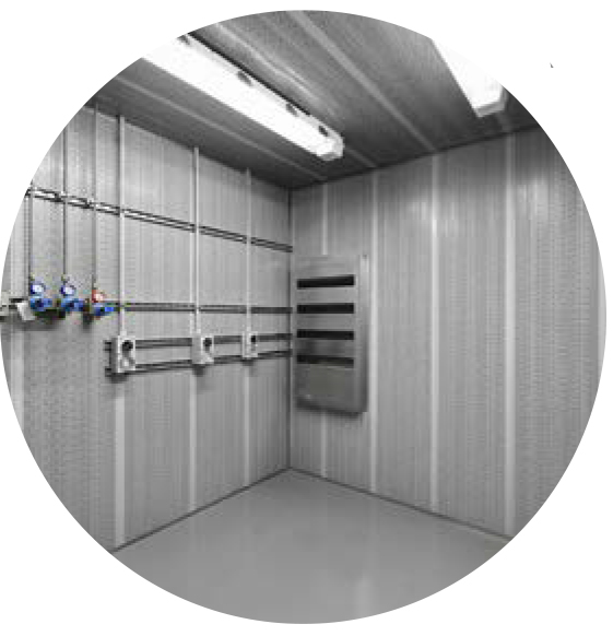
The last resort should be to protect the noise receiver. This type of protection often takes the form of earmuffs or earplugs for individual persons, double or triple glazing for residential properties, or noise havens, which are quiet spaces located in noisy plant or factory areas. However, these solutions impede the activity of the person(s) being protected. Double or triple glazing used to reduce the noise at a property also reduces the amenity of the property. Similarly, ear defender protection is only as effective as claimed when based on the average person. Noise havens offer a quiet space in a noisy work environment but do not protect the worker from the noise hazard in the plant. Up to one third of the workforce is not as effectively protected as they should be. Further, personal protective equipment (PPE) is required to protect workers from a hazard. Employees are still exposed to the hazard, but the likelihood of harm—the risk—is reduced by wearing PPE. If the PPE fails, however, no protection is provided and safety is compromised; whereas if the hazard is removed, the danger is removed.
For the purposes of this article, we will focus on the reduction of the transmission path, as it is most affected by insulation materials.
Controlling noise can depend on many elements, such as cost, practicability, maintenance, and effectiveness. The primary consideration should be to determine the cause, but noise sources are not always obvious, particularly if you have a lot of noisy equipment in one area. Best practice should be to conduct a detailed noise assessment/survey of the area and problem. Specialists should undertake assessments to ensure a correct, detailed summary of the situation. General sound assessments can focus attention on noise sources. Detailed assessments of individual noise sources using sound pressure, sound intensity, and/or vibration velocity techniques provide a detailed picture of the problem. Such understanding leads to effective solutions.
The Transmission Path
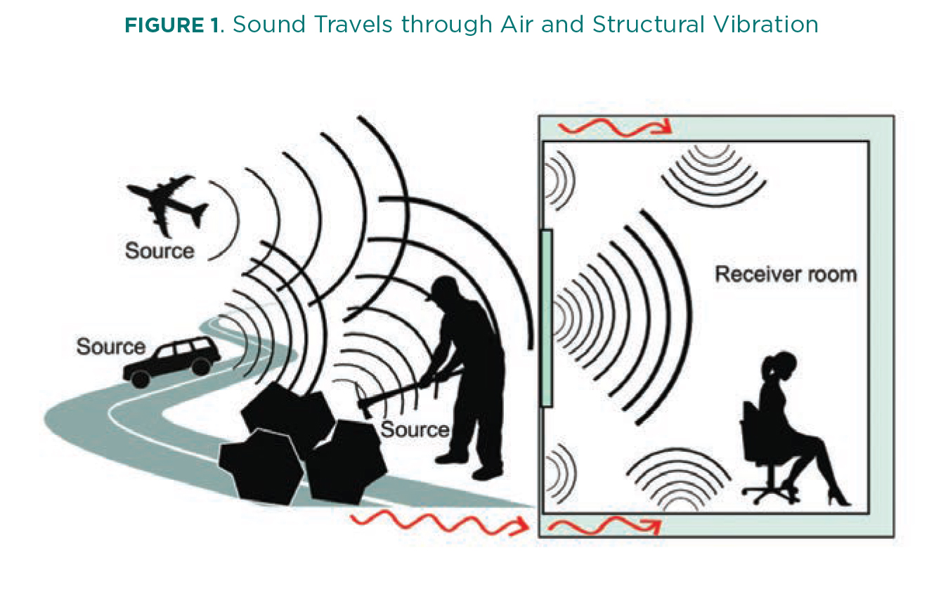
Noise is unwanted sound. Sound is generated by structural vibrations (rotating equipment, pipework, etc.) or aerodynamic flow (exhausts, vents, etc.) and propagates as a quickly varying pressure wave travelling through the surrounding medium (gas, liquid, or solid). Understanding how to control this propagation can be defined by the type of sound generation and its medium and characteristics (e.g., sound level and frequencies).
Sound can travel in air either as an airborne pressure wave (airborne sound) or via a structural vibration—a pressure wave in a solid structure—that then re-radiates the sound into the air (structure-borne sound) (see Figure 1). What we hear is often a combination of both methods of travel. The key is to determine which is the most dominant path and, subsequently, which control method to use.
For airborne sound propagation, we need to either absorb or block the sound. Therefore, sound absorption and acoustic barriers are most effective. For structure-borne sound, we need to either de-couple/isolate the vibration source from the solid structure or dampen the structure to reduce its vibrational energy.
Airborne Noise Control
Sound Absorption
Sound absorption is key when looking to reduce the sound level in an enclosed space. In a free-field environment, sound will continue to propagate away from the sound source, dissipating with distance following the inverse square law. In an enclosed space, such as a room, sound will propagate away from the sound source until it meets a barrier or wall. Sound will then pass through the barrier, be absorbed by the barrier, or reflect back from the barrier. To reduce the reverberant sound level in a room or enclosure, the amount of sound reflected into that space can be reduced using sound absorption materials on the internal walls. Sound absorption materials within the wall construction can help absorb sound passing through the wall.
Applying sound-absorbing materials to a wall of an enclosed space helps control the sound level inside the space. The amount of absorption required depends on the use of the enclosed space—e.g., for speech intelligibility in schools, or for concert spaces or movie theaters. Additionally, reducing the reverberant sound levels in a machinery enclosure or workshop can help to reduce occupational noise exposure.
Sound absorption materials are also a key part of reducing internal HVAC airborne sound transmission through ducts and within pipework acoustic insulation.
Within acoustic design, sound absorbers are classified as one of the following: (a) porous materials, (b) non-porous panel absorbers, or (c) cavity resonators.
Porous Materials
Porous materials are those most readily analogous to insulation materials. They are open cell in nature and often, though not exclusively, fibrous in design (e.g., open cell flexible elastomeric foams [FEF]). Such materials are characterized by a network of interconnected pores, creating small channels and cavities. As acoustic energy passes through these complex channels, the material creates viscous losses through conversion of the acoustic energy as heat. The absorption of acoustic energy is dependent on the frequency of the sound passing through the material. There is low absorption at low frequencies, with absorption increasing as the material thickness increases relative to the wavelength of the sound. As frequency increases, wavelength decreases, and the thickness of the porous material becomes more effective. The thicker the porous material, the greater the degree of absorption across a wider range of frequencies. (See Figure 2.)
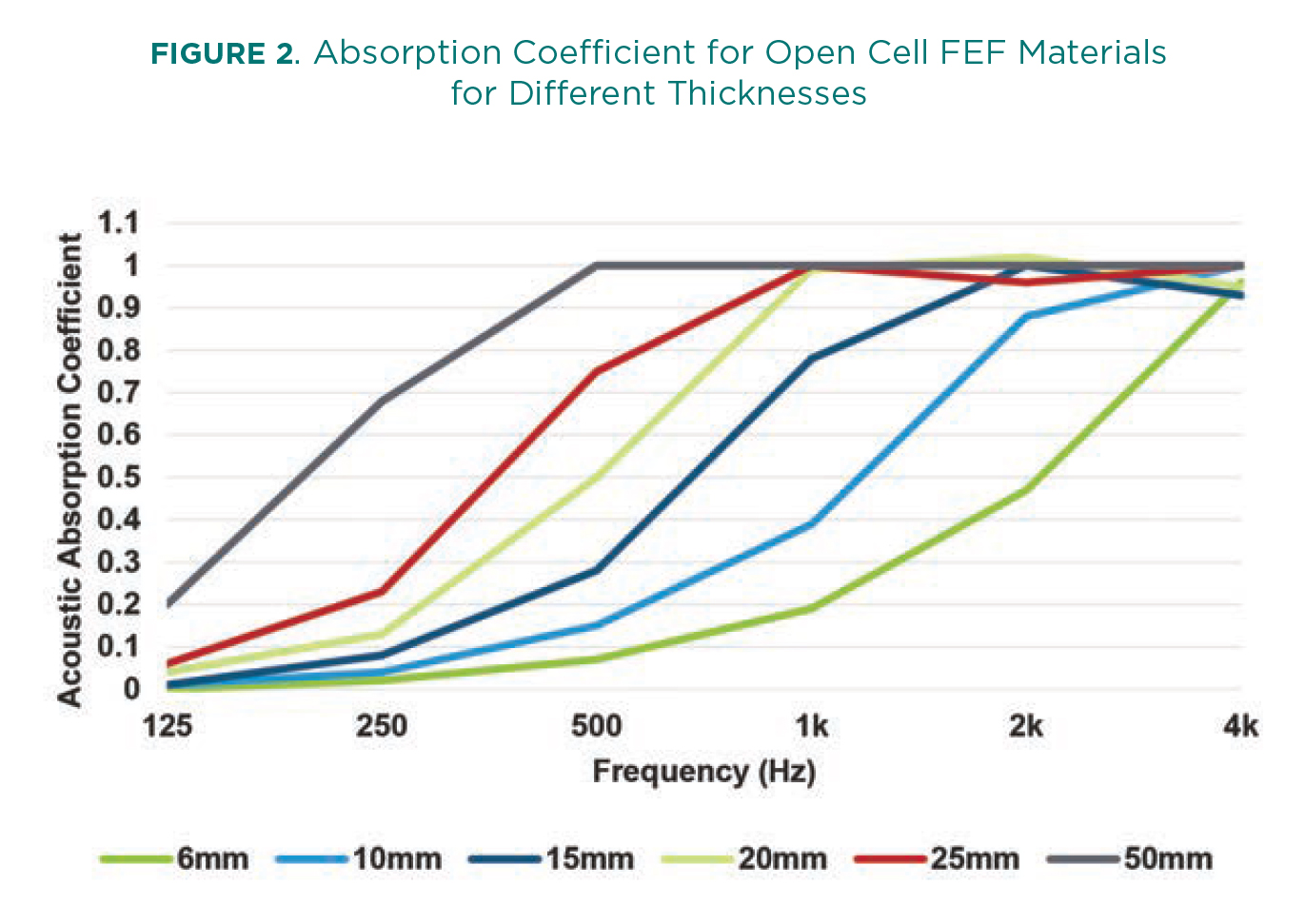
When selecting the sound-absorbing porous material, it is key to understand the frequencies of sound that most need to be reduced, and then select a material and thickness that will best provide such a reduction.
Determining the acoustic absorption of a porous material requires testing in a specialized laboratory to ASTM C423-22/ISO354. ASTM C423-22 also identifies an overall Sound Absorption Average (SAA) for quick reference. This value is an average of the material absorption coefficients in one-third octave bands between 200Hz and 2500Hz.
Non-Porous Panels
Typically mounted away from a solid backing, non-porous panels such as gypsum, metal sheet, or plywood behave differently from porous materials. Sound incident upon non porous panels causes the panel to vibrate. The dissipative mechanisms within the panels’ material properties convert the acoustic energy into heat. Note that the addition of a porous material behind a non-porous panel can help to increase the lower frequency absorption.
Cavity Resonators
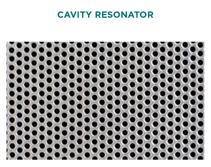
A cavity resonator is a non-porous panel located away from a solid backing, but with a narrow opening. The opening provides a connection between the volume of air behind the panel and the larger space/room/enclosure. This mechanism creates a “Helmholtz Resonator” that absorbs acoustic energy, but only for a narrow band of frequencies near its resonance. It is possible to broaden these frequencies by increasing the number of openings—with a perforated panel—and using porous materials between the panel and the solid backing.
When trying to control the sound inside an enclosed room or space, any (or a combination) of the above systems can be effective. It is, however, necessary to ensure the source sound characteristics are known to select the correct system.
Barriers
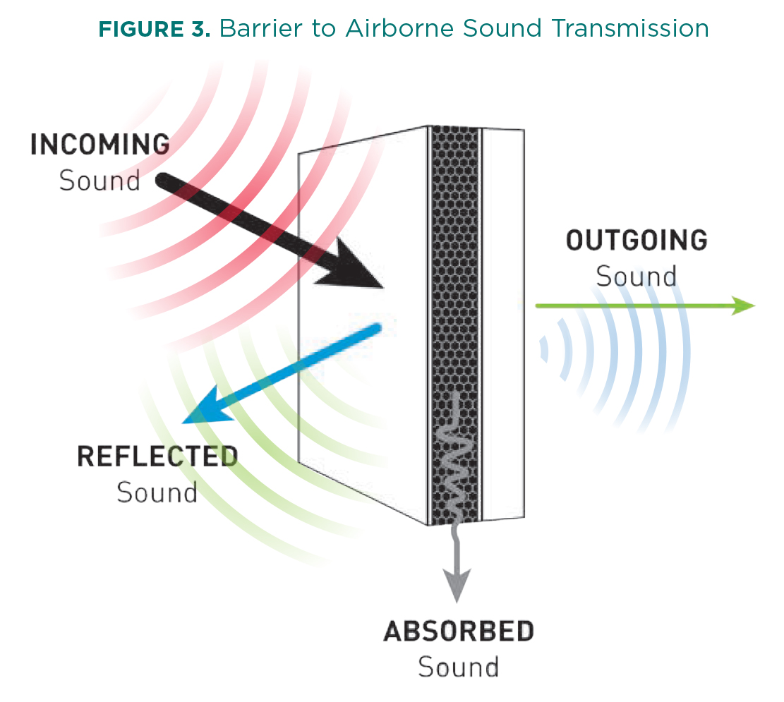
Barriers prevent sound passing through them. They can be walls or fences, but a building/enclosure surrounding a noise source, a machinery/valve jacket, or a pipe or duct insulation covering also function as barriers. A barrier blocks sound from getting from a sound source to a receiver. The noise source remains, the receiver is still there, but the sound transmission path is blocked. The basic performance of a barrier (transmission loss) for airborne sound involves reflection, absorption, and transmission (see Figure 3).
The acoustic transmission loss performance of a barrier depends on many factors. For simplicity, consider a basic incidence-absorption-transmission scenario. The ability of the barrier to impede the sound is defined by its physical material characteristics—e.g., thickness, density, mass, stiffness, and damping. Figure 4 shows the behavior of transmission loss for a single, homogeneous material (a) and a composite, multi-material sandwich construction (b).
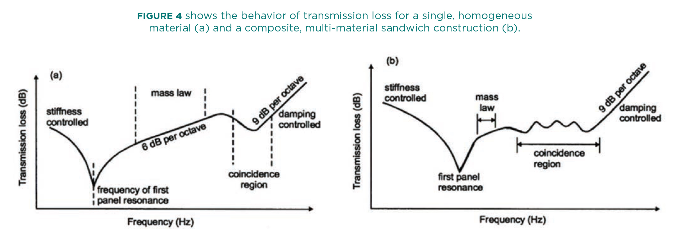
Each barrier has a resonance. Below that resonance, stiffness controls transmission loss. At the resonance frequency, sound is transmitted through the barrier without much reflection or absorption. Around twice the lowest resonance frequency, the mass of the partition dominates the sound reduction. Transmission loss increases by 6 dB per doubling of mass. Mass increase means the panel vibrates less in response to incident sound waves. Consequently, less sound energy radiates on the other side.
However, mass is not the only factor to consider in a barriers’ acoustic transmission loss.
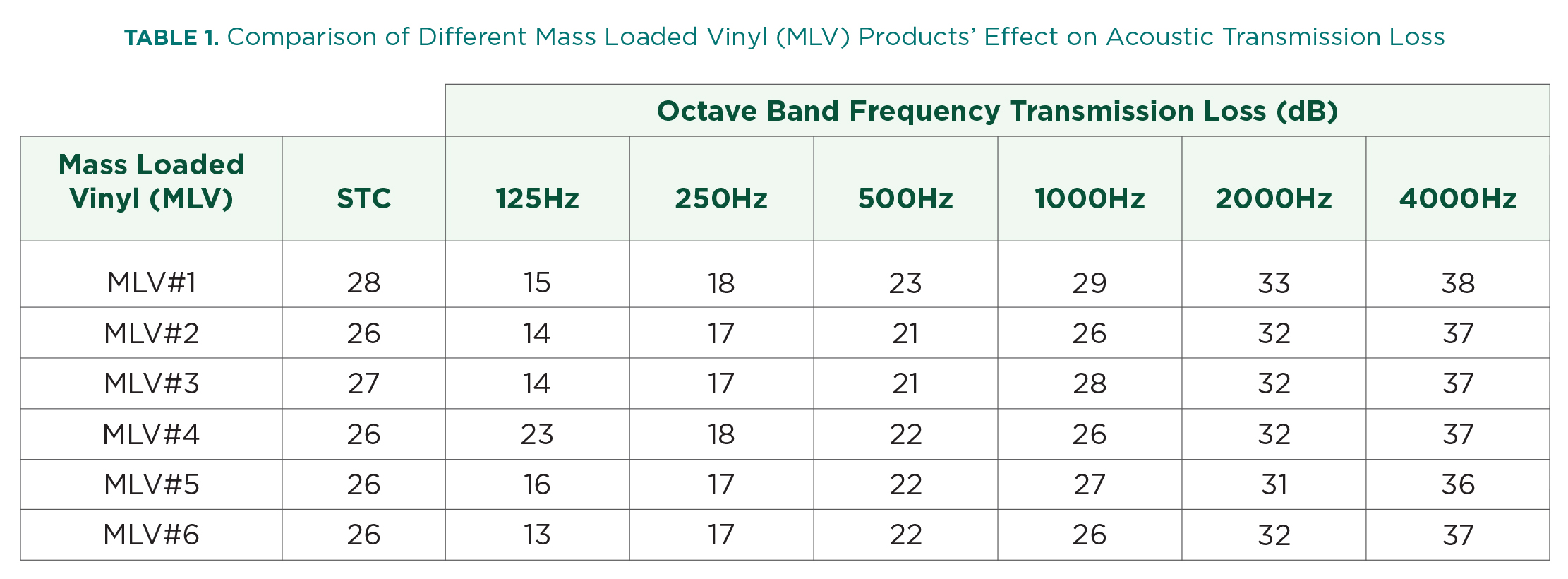
Table 1 (below) shows six different mass loaded vinyl (MLV) products from six different manufacturers. All have the same mass and produce similar sound transmission class (STC), but the actual performance can vary. When selecting an MLV, or any barrier, matching the barrier to the noise source characteristics (e.g., frequency) ensures the most effective solution.
At higher frequencies, there is a coincidence region where bending waves occur through the barrier. As the bending wave’s velocity increases with frequency, the wavelength of the bending wave differs from the incident sound wave that created it, except where the bending wave speed in the material equals the speed of sound in the air. Here, all the waves coincide and reinforce each other, in phase. This reduces the sound reduction performance of the panel around this frequency. Every material has a coincidence frequency where the transmission loss reduces considerably. For more complex barriers made of several materials (a sandwich panel), the coincidence region is often wider than for a single homogeneous material.
Generally, the best acoustic barriers tend to be high-mass, limp, highly damped materials with a high weight-to-stiffness ratio.
Structure-Borne Noise Control
Isolation
At its most basic, anything that vibrates can produce sound waves. Depending on the material and the size of the vibrating object, the amount of sound generated differs. Exciting a tuning fork, causing it to vibrate, and holding it in the air, it is audible but quiet. However, placing the base of the fork on a desktop, for example, causes the loudness to increase significantly. The tuning fork is vibration—coupled with the desktop, it forces the desk to re-radiate the excitation vibration of the fork as sound. Because the desk has a larger surface area, the loudness increases. This process of vibration coupling is important when considering industrial equipment such as rotating machinery on a metal skid or an HVAC air handling unit (AHU) connected to HVAC ducting. Treating the item of equipment alone is insufficient. Isolating the equipment from connected structures can be equally, if not more, important.
Similarly, a washing machine on spin cycle can couple with a building structure and cause other structures in the building (walls, floors, ceilings, etc.) to vibrate and re-radiate the sound of the washing machine. This causes issues of disturbance in other parts of the building and is extremely hard to treat without reducing the noise at source.
The most effective way to control these situations is to “vibration isolate” the excitation source from its surrounding structure. Various techniques achieve this, usually through rubber mounts or spring connections.
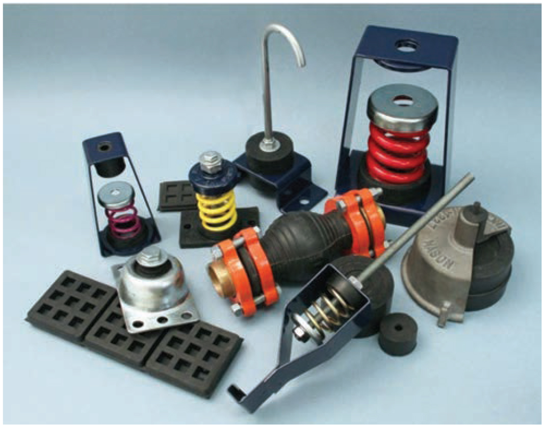
Selection of the correct anti-vibration mount(s) should be undertaken by an expert or supplier, as selection of the correct system and materials must allow for the operation of the machinery, frequencies, weight, balance, etc.
A good example of a vibration isolation system would be one for the AHU for an HVAC system. The AHU has a rubber-type collar separating the unit from the ductwork. This type of connection reduces or removes the machinery vibration of the AHU coupling to the duct work. The duct work is thin steel, with a high surface area. It would very easily re-radiate the AHU machinery noise throughout the building. Note that the noise from HVAC systems is primarily, though not always, generated by the fan as airborne sound that travels through the duct. Consequently, acoustic absorbing insulation materials are used as a possible solution. These would not work if the sound propagation path was mechanical vibration of the duct itself.
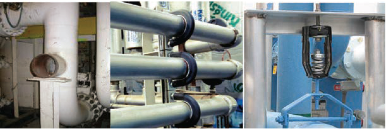
Process pipework acoustic insulation systems reduce the sound emitted from the pipe surface. If the pipe is physically attached to a steel pipe rack, the pipe wall vibration is coupled directly to the pipe rack. The pipe rack is often steel and easily re-radiates the pipe noise. When treating pipework noise, it is important to not only insulate the pipe with suitable acoustic insulation but also to vibration isolate the pipe from the supporting structure.
For a vibrating sound source, isolate it from its supporting structure if that structure is likely to re-radiate the noise.
Damping
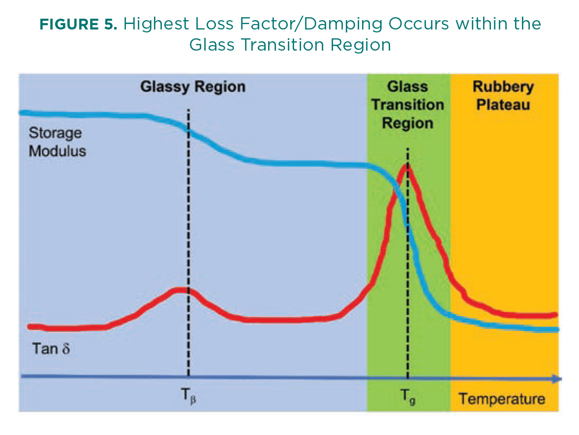
If isolation is not possible, it becomes necessary to try to reduce the amount of vibration energy in a coupled structure using damping. A damping material reduces the vibration of a surface, minimizing transmitted vibration and, thus, radiated noise by damping out structural bending waves. Damping materials reduce the kinetic energy present in a system by transformation into thermal energy. The degree to which a material can provide damping is presented as the loss factor. The loss factor (η or Tan δ) of a material is the ratio of a material loss modulus and the storage modulus, and it varies with frequency and temperature. The highest loss factor and, therefore, damping occurs within the glass transition region of a material (see Figure 5). Selecting the correct damping material, aside from the damping system used, should be a function of the operating temperature and frequency.
For non-porous material panels, damping is an important parameter, especially below first resonance and above the coincidence frequency. However, for porous insulation materials, damping is a key factor in reducing the thickness of pipework acoustic insulation systems. Within aerogel blankets, the embedded aerogel within the blanket damps the blanket fibers, which has a dual effect. First, the sound wave passing through the damped blanket must work harder as the energy is better dissipated by the blanket fibers. Additionally, the porous material acts as a spring in a mass spring system. As a damped mass spring is more effective at reducing the vibration energy, so a damped porous material is better at removing vibrational energy from the system. This is particularly important in pipework insulation systems, and it is one of the reasons why an aerogel acoustic pipe insulation system can be much thinner than a standard mineral wool acoustic system. In FEF-based acoustic insulation systems, the closed cell FEF acts as a spring to reduce vibration transmission. The addition of an open cell FEF acoustic material acts as a damped airborne acoustic absorber, and the elastic barrier materials function as a mass barrier. For metal clad systems, the use of a viscoelastic barrier can be even more efficient than an elastic mass barrier. This is due to the higher loss factor (damping) of the viscoelastic barrier, which reduces the ability of the metal cladding to radiate sound.
Which Noise Control Method to Use?
Example: Machinery Enclosures
Where there is a high noise generating item of equipment, e.g., a pump package, it can be possible to enclose the package. The best practice solution for an enclosure could be considered a steel enclosure with MLV on the inside of the box; a porous, sound-absorbing material such as open cell FEF or mineral wool inside that; a thin (25 micron) polyurethane sheet to reduce moisture/chemical ingress; and a perforated metal sheet. This type of design provides both sound absorption inside the enclosure—reducing the reverberant sound energy—and a physical, damped barrier.
The choice of material thickness depends on the sound source characteristics/frequencies and the level of reduction required. For example, if a 2” sound absorption material is required, selecting the open cell FEF option is likely to add more mass and damping to the enclosure system than may be achieved with mineral wool. Using the FEF would therefore improve the barrier transmission loss. If this additional reduction were not required, the use of mineral wool could be suitable.
Additionally, care should be taken to avoid any physical connections from the noisy equipment in the enclosure to the enclosure itself. This could allow structure-borne noise transmission.
Example: Pipework Acoustic Insulation
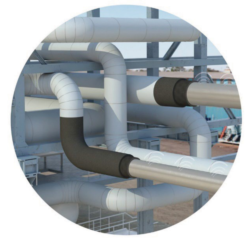
Effective pipework insulation must incorporate all the above noise control elements. The vibrating pipe wall radiates airborne sound. When attaching an insulation system to the pipe, the pipe wall vibration can be transmitted to the insulation cladding and
re-radiated by the cladding as airborne sound. Acoustic insulation must reduce both airborne and structure-borne contributions.
The porous layers provide acoustic absorption and structure-borne vibration isolation between the pipe wall and cladding system. The cladding system requires sufficient mass and suitable low stiffness to function as an airborne acoustic barrier, with enough damping to reduce re-radiation from the external cladding material.
Additionally, care should be taken to use anti-vibration mounts to support the pipe on the pipe support structure to avoid structure-borne noise.
Summary
The use of insulation materials to reduce noise is highly dependent on the nature of the noise source, the path the noise takes to get from the source to the receiver, and the amount of noise reduction needed. Proper assessment of the nature of the noise problem should be sought to ensure the correct control methods are selected. To reduce airborne noise, the use of suitable sound-absorbing and/or barrier materials is required. For structure-borne noise control, the use of vibration isolation or structural damping is required.
Richard Pamley, BSc, MSc, CEng, is the Global Acoustics Manager for Armacell Energy. Pamley has more than 25 years’ experience in sound and vibration, working as an International Consultant Engineer in the energy sector and as a Senior Scientist in vibro-acoustic material research. He has a bachelor’s degree in Physics with Acoustics from University of Surrey (UK), a master’s degree
in Sound and Vibration Studies from the Institute of Sound
and Vibration Research, University of Southampton (UK),
is a Chartered Engineer, and is a Member of the Institute
of Acoustics.