Optimization of Folded Ceramic Fiber Refractory Furnace Modules
The Approach
Modular refractory systems have been widely used for several decades. In this time period, module design has been advanced in an effort to combat issues such as shrinkage, water penetration, and attachment system failures. Ceramic fiber modules allow heat to shed quickly and facilitate safe, rapid installation. The overall result is a more efficient, cost-effective alternative.
The construction of the module is designed to create a no-gap environment upon unbinding. Ceramic fiber module systems provide an energy-efficient solution that can aid in alleviating the need for controlled start-up after installation. While module systems can be custom engineered, the systems are also utilized as a commodity item installed as a “one-size-fits-all” application. When installations are performed with a “blind” or “one-size-fits-all” strategy, the resulting system will often experience hotspots and failure of the insulation, attachments, or both. The differences in custom versus standard modules will be addressed in this article.
Applications
Folded ceramic fiber modules are used in various furnace and heating applications. Common uses include annealing and tempering furnaces, combustion chambers, oxidizers, burn-off ovens, hydrocarbon reformers, kilns, incinerators, ducts and flues, and more. A primary benefit of ceramic fiber is the reduction of time required to cycle furnace temperatures up and down.
Important Factors
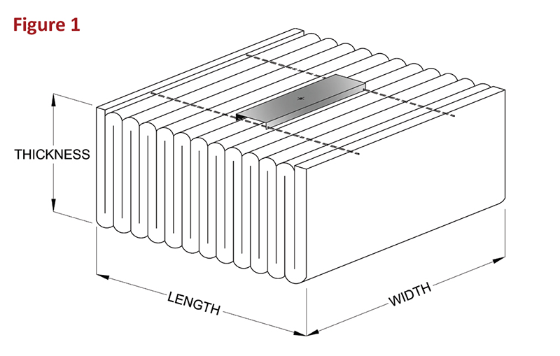
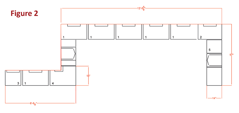
Select manufacturers have the ability to produce custom modules while others offer limited sizing options. End users must have an understanding of certain critical factors in order to have a successful project. Factors that require attention are the orientation of the fold, the length, width, and thickness (see Figure 1). Module density and thickness must be considered to meet the requirements of the furnace. Heat flow analysis can determine the most effective module thickness, density, and blanket chemistry. Upon removing the bands, the compression of the module is released. This process fills the voids along the path of the folds and is designed to compensate for shrinkage. Cut edges perpendicular to the folded path shrink without the benefit of compressive force. Installation of compressed batten strips of blanket between cut-edge grain sides and their adjacent rows help to counteract this occurrence (see Figure 2). A stainless-steel segment or beam acts as a backbone that pins each fold to the next. The shape of this segment is determined by the type of attachment hardware used. Module manufacturers use drawn wire or folded plate yokes as well as channel braces or similar variations to separate the beam holding the folds in place.
Attachment Hardware and Installation
One installation practice for refractory modules is the use of an electric gun, which passes a high current through a stud with a weld-metal tip and ferrule at the base. A current is applied to the stud and employs a delay between weld heating and rotation/compression of the stud. The process breaks the ferrule and turns the nut onto the stud. While this process is expedient, a pull test is required for each module to determine if the weld has held sufficiently to keep the module in place.
Another method of attachment allows for pre-welding of a stud via a stud gun or shielded metal arc welding (SMAW) machine. Visual and mechanical testing of each weld is possible before the modules are attached to the stud. Drawings are required for this type of installation, showing locations of each stud along the furnace shell to ensure the modules fit properly into the design.
H- and U-anchor installation techniques are also widely used. In this case, the modules are “pleats” and have no internal steel support system. The pleats are impaled on “H”or “U” style anchors at each joint. This installation must be executed with care to ensure that shrinkage gaps do not occur in areas of anchor attachment due to the anchors being placed at the module joints. It is necessary to prevent exposure to the furnace heat should shrinkage occur.
A yoke-beam arrangement in a blind-weld circumstance creates an upper limit to the amount of ceramic fiber that can be supported (typically 1 square foot per yoke). Upon inspecting the lining, should a hot spot develop, furnace operators and maintenance personnel often find the only things left attached to the furnace shell are the weld-stud and yoke. What remains must be removed from the shell and replaced with a new module.
Engineered systems are better for the prevention of hot spots. The channel and beam backbone is an alternative that allows for broader fiber coverage per anchor and a stiffer lattice for the cold face of the module. This approach allows for the optimization of module arrangement required for special furnaces. Beam spacing, anchor location, channel dimension, and thickness can all be varied for customization. Vertical corners can be surrounded with fiber via a 90-degree steel bend and fiber notch called a bullnose. This eliminates hotspots in transitions between ceilings and walls. A well-engineered system of channel-supported beams with modules of varying dimensions provides the optimum blend of anchor locations and shrinkage consideration. This engineered approach to lining is preferable for desired results.
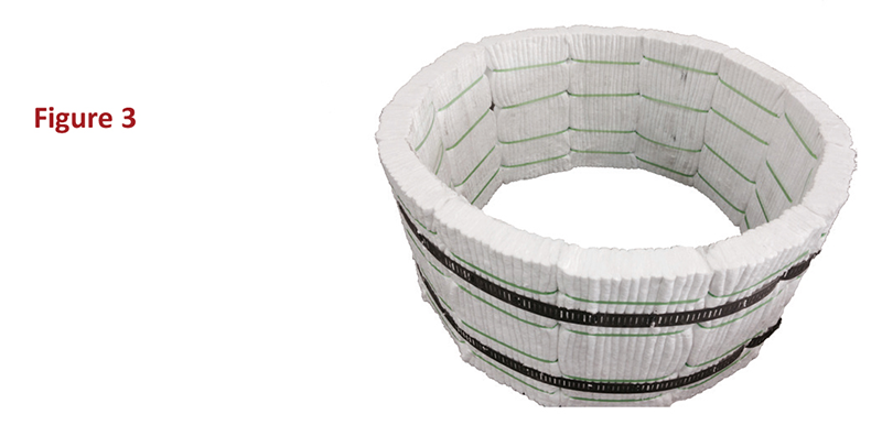
The “Z-Flex” module is widely used in complex furnace geometries such as tubular shells and ducts or compound transitions (see Figure 3). With this type of chained module, a cold-face stainless steel strap is used to connect individual modules together. Generally, this module takes a fraction of the time required to attach individual modules to surfaces. Installation of Z-Flex in round applications requires almost no layout. L-type and T-type anchors hold the chained panels down to the furnace shell. The use of straps and anchors results in a safety factor unmatched by traditional anchoring methods.
Conclusion
There is no “one-size-fits-all” means of furnace coverage with folded ceramic modules. An engineered approach to attachment, blanket chemistry, fold density, geometry, and shrinkage are critical factors in furnace lining. Most module manufacturers should have the ability to provide custom engineered modules to maximize performance, longevity, and cost management.