Shipboard System Insulation design using 3E plus®
The development of effective and efficient mechanical insulation systems aboard ships present many challenges to the designer. Ship construction regulations and material certifications are rigid, and strict adherence to performance specifications mandate the insulation system design be validated through rigorous analysis. Additionally, due to the expansion of international trade and U.S. national defense priorities, ocean-going vessels often sail through extreme conditions. The mechanical insulation system designer must be conscious of the limits for both temperature and relative humidity. A single ship may experience limits ranging from summer conditions with temperatures as high as 130°F and 90 percent relative humidity to winter conditions with temperatures as low as 0°F. These regulatory and environmental variables present a formidable challenge to insulation specification seeking to maintain design compartment temperatures throughout the vessel.
Beginning in 2002, one insulation contractor’s new construction project team was tasked to assist in the design of a new shipbuilding program with the ship builder, General Dynamics (GD) NASSCO. This program, named the T-AKE Dry Cargo/ Ammunition Ship, was developed to provide a ship capable of delivering ammunition, provisions, stores, spare parts, potable water, and petroleum products to carrier battle groups and other naval forces, serving as a shuttle or station ship. Achieving the stated mission required several cargo holds that were at times refrigerated to -9°F, as well as other cargo holds maintained at 84°F. Coupled with the extreme design challenge presented by environmental conditions, the contractor and GD NASSCO’s assignment was to design the insulation for the mechanical ventilation systems that would maintain conditioned air temperatures in various compartments and prevent condensation formation on the duct and pipe surfaces.
In 2003 and 2004, the detailed insulation design of the T-AKE program began to take shape. New requirements surfaced regarding insulation thickness of secondary coolant (brine) piping; specifically, American Bureau of Shipping (ABS) Rule 6-2-6/ 23.3.4, which states:
“Secondary coolant piping, valves, and fittings whose working temperature is below the normal ambient temperature are to be effectively insulated. The insulation is to be sufficiently thick to prevent the formation of moisture on the pipe surface at a relative humidity of 90 percent.”
Contractual requirements dictated that GD NASSCO and the insulation contractor provide insulation thickness calculations for the secondary coolant (brine) piping that ensured adequate thickness to prevent moisture formation. Additionally, significant quantities of ventilation ducting traversing multiple compartments now were required to be insulated due to increased air volume movement and rate of changes per hour.
The engineering challenge was to provide acceptable calculations (as contractually required) for the brine piping and condensation prevention/heat loss calculations for ventilation duct. Many calculations were required because the piping and ventilation ducts traversed many compartments, each having specific winter and summer design temperatures, relative humidities, and relative wind speeds, along with variation in pipe and duct size. With the unprecedented volume of calculations required, and the absence of any definitive source to supply the detailed thickness requirements that met the team’s needs, the heat loss analysis computer program 3E Plus® emerged as the preferred design tool.
In their research of 3E Plus, the team learned that ASHRAE had used the software to assign insulation thickness of varying types in its 1998 Refrigeration Handbook, Chapter 32, “Insulation Systems for Refrigerant Piping,” which lent immediate credibility to the design. The project management team had to reach a certain level of comfort that the software would provide consistently accurate thickness recommendations for the variables the team specified. To achieve this goal, the team validated the accuracy by performing a number of manual calculations on dissimilar circumstances. Every manual calculation was within 97 percent of the 3E Plus calculation.
The insulation design for the refrigerated brine system proved exceptionally challenging. As noted earlier, in the calculation of piping insulation thickness, ABS regulations require no moisture formation on the surface of the insulated piping at a relative humidity of 90 percent. As a result, every compartment the brine piping traversed, from the chiller unit locations to the actual cargo space that holds the diffusing equipment, required a separate calculation. The easy road, from a design perspective, would have been to assign one thickness throughout, accommodating the most onerous compartment temperature. During construction, however, this approach ultimately would have led to increased material and labor costs due to confined working areas and condensed pipe runs. From an accuracy and construction viewpoint, it was determined that the best approach was to perform calculations for each compartment through which the brine piping traveled.
Working in concert with the team’s engineering colleagues at GD NASSCO, the insulation contractor compiled the compartment variables necessary to calculate the correct thickness:
- Summer or winter season design temperature
- Relative humidity
- Wind speed
- Pipe diameter
Although the regulatory requirements were a contractual obligation, the team’s use of 3E Plus in calculating design insulation thickness also provided a more practical solution: supporting system operation by preventing moisture condensation and intrusion. Based on the design temperatures of the brine system and the compartments through which the system traveled, high vapor pressure was a major concern. The design pipe insulation thickness was fundamental in preventing moisture condensation, accumulation, intrusion to the underlying piping system, and potential insulation system failure. Since the costs to replace the insulation system components in the event of a failure would have been prohibitive, it was critical to do the job correctly. 3E Plus provided the team with the detailed calculations necessary to ensure regulatory approval and the confidence that the prescribed thickness would perform as required under the extreme shipboard conditions.
Heating, ventilation, and air-conditioning (HVAC) functions for shipboard applications are similar to land-based treatments, as they control temperature, humidity, and quality of the air in the various spaces on the vessel. Shipboard HVAC system types also vary based on the ship class. In this scenario, the T-AKE vessels use terminal reheat systems. One unique design consideration is that ships operate in a wide range of weather conditions and can be subjected to large variations in climates within short periods. There are also various climates inside these ships. For example, on T-AKE vessels, there are more than 750 compartments with varying HVAC requirements, utilizing more than 50 air handlers with off-coil temperatures designed to meet their specific needs. These compartments vary in use from machinery spaces to air-conditioned cargo holds and accommodations, including living or service spaces.
The insulation design prevents condensation and limits sensible heat added to or extracted from the air in the duct as it passes through the various compartments on its path to the final destination. The most stringent design calculations were based on the specification requirement to install insulation on parts of air-conditioning systems where the space dew point is more than 4°F higher than the duct air dry bulb temperature. There also were requirements for treatment on any outside air passing through air-conditioned spaces and supply systems inside machinery rooms. The team had to define the required treatments on each duct run based on the scenarios that existed. By using 3E Plus to perform these calculations, the team ensured that the systems were not under-insulated, saving material costs in some large areas. Many scenarios were repeated, but without using 3E Plus as the design tool, significantly more time would have been required to determine the proper treatments.
Performance of Insulation Design
The first five vessels of this program have been delivered, with the first three seeing significant tours in support of the U.S. naval fleet. The insulation contractor has been a part of the visual inspection team of one of the delivered ships, and it appears that all insulation systems—particularly the refrigerated brine system and all ventilation ducts—are performing as designed. To date, there have been no reported issues regarding the performance of insulation systems for the brine system or ventilation ducts.
Generally, there has been no negative feedback from the fleet, which suggests that the mechanical insulation systems are working as intended. This further validates 3E Plus as an integral and accurate part of the design efforts.
Conclusion
Insulation design for land-based HVAC systems is, under normal circumstances, a challenge. On ocean-going vessels such as the T-AKE vessels, which travel through a wide variety of climactic conditions, it is an even greater challenge.
The 3E Plus program enabled the mechanical insulation system designers to achieve the optimal insulation design on two key systems for the T-AKE vessel program. This, in turn, allowed the insulation contractor to install reliable and well-designed mechanical insulation systems, thereby maintaining the ship’s intended capabilities and missions.
3E Plus is available free from the North American Insulation Manufacturers Association.
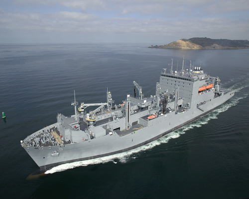 Figure 1
The T-AKE Dry Cargo/Ammunition Ship is designed to deliver ammunition, provisions, and other supplies to carrier battle groups.
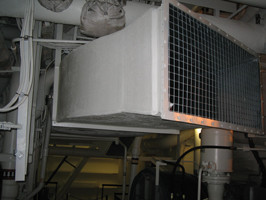 Figure 2
A ventilation supply duct and protective screen. The insulation thickness was designed to accommodate the variables for this compartment to prevent condensation formation.
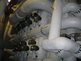 Figure 3
A refrigerated secondary coolant (brine) system manifold. Insulation thickness was designed to allow for adequate pipe clearances while preventing moisture formation.