The Boiler Circulatory System: Beyond the Steam-Generating Boiler
The primary purpose of a steam-generating boiler is to make steam to generate electricity. Super-heated steam comes from a boiler to a turbine and turns the turbine blades to create electricity. How water enters and leaves a boiler is called the boiler and steam circulatory system. The pipes and tubes that make up these circulatory systems have many parts.
For a boiler to make steam continuously, it must have water circulating through its tubes. Boilers use thermal circulation, in which water is exposed to heat and begins to turn into a water/steam mixture. Since a combination of water and steam is less dense than water, gravity will cause the water to move down and the steam/water mixture to rise.
All steam-generating boilers have the same systems described below. For this article, a radiant power pulverized coal–fired boiler is our example.
A radiant power pulverized coal–fired boiler is divided into three areas:
- furnace area, where the heat source is located
- super-heater area, where super-heated steam is made
- convection pass or heat recovery area, where the economizer is located.
Within these areas, the combination of water/steam circulates throughout the boiler. Figure 1 shows a typical radiant boiler circulatory system.
Water/Steam Circulatory System
Before water can enter a steam-generating boiler, it must first be treated and cleaned of minerals and alkalis (e.g., iron or calcium) that could clog the tubes and prevent proper circulation. After the water has been treated or cleaned, it is pre-heated in feedwater heater tanks. The pre-heated water then enters the boiler at the economizer inlet header. The piping system carrying the water to the economizer inlet header is called the feedwater piping system. (Note: The temperatures shown in Figure 1 for each system are taken from historical data and will vary depending on boiler design and operation.)
For a radiant boiler, the temperature for the feedwater heater to the economizer inlet is approximately 483ºF (for an industrial boiler or fluidized bed-type boiler, the temperature would be approximately 100ºF less). The water circulates up through the economizer tubes to the economizer outlet header, where it reaches 576ºF. From the economizer outlet header, the water/steam goes through 8 in. IPS economizer connecting pipes to the steam drum.
The steam drum is 6.5 ft in diameter and collects and distributes the water/steam as it continuously circulates throughout the boiler. Once the water/steam enters the drum from the economizer outlet header via the economizer connecting pipe, it is forced by gravity down pipes called downcomers.
Downcomers are large diameter pipes (25 in. IPS) that take the water/steam coming from the steam drum down to the lower water wall headers of the convection pass and furnace walls.
Supply tubes (5 in. diameter) supply the steam/water from the downcomers to the individual lower water wall headers. The water/steam then rises through the wall tubes (natural thermal circulation) until it reaches the upper water wall headers. The temperature of the water/steam has by this time reached 688ºF. Riser tubes, so named for the water/steam rising from the upper water headers, take the 688ºF water/steam back to the steam drum.
The water/steam circulatory system ends inside the steam drum. However, there is still one more step before the steam enters the next circulatory system. The water/steam mixture entering the drum still contains moisture (water) and so must enter the steam/water separation area in the upper half of the steam drum. The steam/water separation area consists of many cylindrical tubes called cyclone separators. Cyclone separators spin the wet water/steam mix in a cyclonic action, separating the water out of the wet mixture by centrifugal force. The wet moisture falls down into the lower half of the steam drum, where it is mixed with the water/steam coming from economizer outlet header, goes into the downcomers, and begins the circulatory process all over again.
The super-heated steam circulatory system begins with the now dry 688ºF steam. The dry steam rises out of the steam drum from the cyclone separators via steam outlet connection piping at the top of the steam drum. The steam outlet connection piping takes the dry steam to the super-heated steam circulatory system of the boiler.
Super-Heated Steam Circulatory System
The super-heated steam circulatory system is where the dry steam from the boiler is super-heated and sent to the electric generator or turbine. Tubes, bundled into sections with multiple loops, are suspended inside the boiler, where hot flue gases from the furnace pass around these tube banks. The number of super-heater tube banks is based on the boiler size and steam outlet temperature requirements.
The super-heated steam circulatory system begins with the 688ºF dry steam coming from the steam drum via the steam outlet connection piping to the primary super-heater inlet header. The steam circulates through the primary super-heater inlet and outlet tube banks, circulating up and down until it reaches the primary super-heater outlet header. The temperature of the steam has now reached 811ºF. A connecting pipe transfers the 811ºF steam to the secondary super-heater inlet header. Between the primary outlet header and secondary inlet header are spray water attemperators. Attemperators are headers with sensors that can monitor and control the temperature of the steam leaving the primary super-heater outlet header. They are so named because they spray water or wet steam as a means of temperature control.
The 811ºF temperature steam circulates through the secondary super-heater tube sections, going up and down until it reaches the secondary super-heater outlet header. The temperature of the dry super-heated steam is now 1,005ºF.
The tube banks of the primary and secondary super-heater sections are above the furnace arch tubes. The water wall tubes directly under the tube banks are sometimes referred to as the super-heater floor tubes. In Figure 1, notice that the placement of the primary and secondary super-heater tube sections is in the middle of the unit, directly between the convection pass (heat recovery area) and the furnace area of the boiler. Also note that the secondary super-heater tube sections are in front of the primary super-heater tube sections, capturing more of the maximum amount of furnace heat.
Associated Piping
All exposed piping on the exterior of the boiler requires insulation and finish material (e.g., aluminum jacketing). Understanding the source temperature of the piping system requiring insulating is paramount. The temperature of the drain lines from the economizer inlet is different from that of the drain lines of the lower water wall headers. Soot blower piping can come from either the primary outlet header or the secondary outlet header.
The insulation thickness should be based on where the piping is coming from. There is a lot of individually insulated piping of various sizes. Refer to the typical radiant boiler piping take-off in Figure 2, which shows more than 3,500 lineal feet of individually insulated piping and more than 2,800 square feet of mineral wool blanket for piping that can be bundled.
Conclusion
Understanding the water and steam circulatory system of a boiler is the first step in proper boiler design. A boiler’s primary function is to make steam to generate electricity. Only by knowing the boiler circulatory systems, their temperatures, and boiler function will designers and installers be able to properly insulate the piping systems and maximize energy efficiency. The better our understanding of the steam circulatory system of a boiler, the better and more cost-effective the insulation systems will be.
References
The information contained in this article has been obtained primarily from public sources, without direct input from any of the boiler manufacturers.
Combustion Fossil Power, Combustion Engineering, Inc.,
4th Edition (1991).
Steam, its generation and use, Babcock & Wilcox Company,
40th Edition (1992).
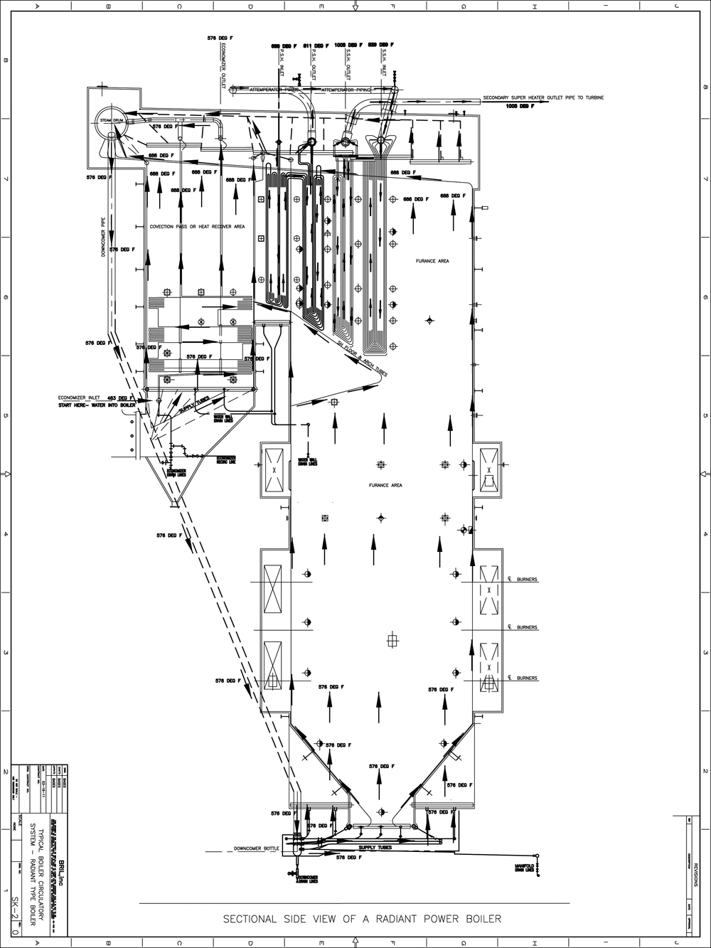 Figure 1
Typical radiant boiler circulatory system
 Figure 2
Typical radiant boiler piping take-off
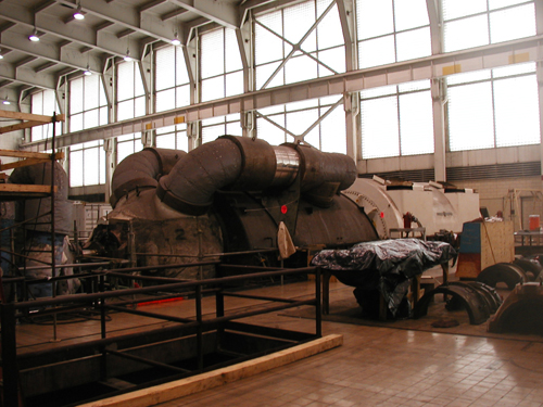 Figure 3
Electric generator
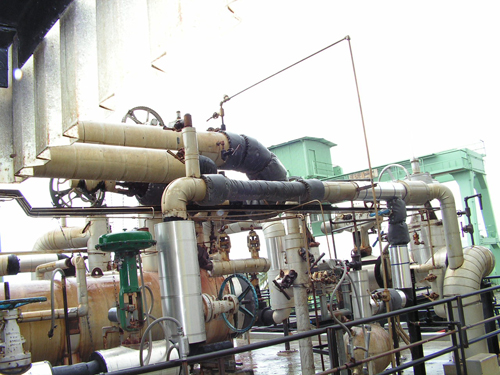 Figure 4
Feedwater heating and pumping