The Key to Reliable Electrical Heat Tracing is Proper Thermal Insulation
Electrical Heat Tracing
A significant number of industrial and commercial piping systems require temperature maintenance. Both freeze protection and process temperature maintenance can indicate the need for heat tracing. Sometimes temperature maintenance can simply be accomplished by installing only thermal insulation. In other cases, however, temperature maintenance must be provided by the addition of heat in the form of electrical heaters, steam tubes, or hydronic fluids. This article will mainly focus on electrical heat tracing, the choice of many of new installations in both industrial and commercial projects. In 1960, about 95% of heat tracing was steam and in 1995, because of improvements in electrical tracing, that number dropped to between 30% and 40% of new installed tracing.
Reliability Requirements
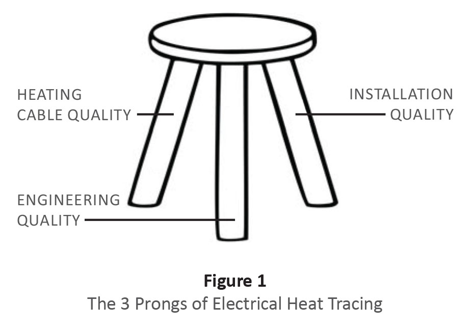
To make use of a visual symbol, electrical heat tracing is like a stool with 3 legs (see Figure 1). One leg is “heating cable quality” (heat trace cable and thermal insulation); the second leg is “engineering quality” (choosing the proper wattage, thermal insulation, ambient temperature, safety factors, etc.); and the final leg is “installation quality,” or the quality of the installation of the piping system and heat tracing system. If any one of the legs is compromised, the system may not provide expected performance. Break any one of the legs and the system will not “stand.”
Heat Transfer
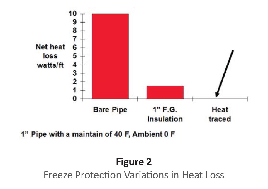
In regard to heat transfer, the first concept one must understand is the value of thermal insulation. A 1-inch pipe will lose 10 watts per foot with no thermal insulation, but will only lose about 1.5 watts per foot with 1 inch of fiberglass thermal insulation. This 1 inch of insulation will also produce a 40°F temperature difference, which could provide freeze protection in a very low maximum ambient (see Figure 2).
The basic formula for heat loss is:
Q=UA(T1-T2)
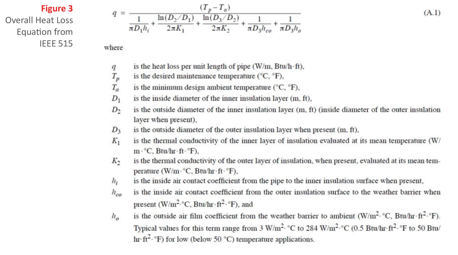
Where Q equals the quantity of heat, U is a heat transfer coefficient, A is the Area, and T1-T2 is the temperature difference. The Institute of Electrical and Electronic Engineers (IEEE) provides a more accurate, though complicated, heat loss formula (see Figure 3) by adding in pipe heat loss and other secondary factors.
This formula has logarithms because of the cylindrical form of the pipe with decreasing heat flux as the heat moves away from the pipe to the weather-proof cladding on the outside of the thermal insulation. The bottom line remains that the addition of minimal thermal insulation in our previous example reduces heat loss by about 800%.
Problems in systems are generally found near “thermal inconsistencies,” such as valves, elbows, tees, and the like. In these instances, careful engineering and excellent thermal insulation are critically necessary. Straight pipe with dry thermal insulation rarely freezes; it is the physical location of the pipe that leads to more heat loss. This brings another failure modewet thermal insulation. In some cases, wet thermal insulation can be worse than no thermal insulation because of the increased surface area losing heat and the increased thermal conductivity of wet thermal insulation.
Computer Modeling
The advent of computer modeling permits analysis under different conditions. Figure 4 shows a valve heat transfer computer simulation.
Electrical Heating Case Study
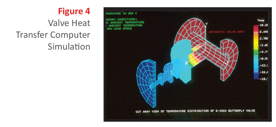
However, the model in Figure 4 may give a false impression; the real world installation rarely follows the idealized computer model. It is, however, a good starting point for understanding heat transfer. Larger temperature differences can create modeling issues, especially when radiation heat transfer is involved. This usually occurs with a high maintain temperature and a low ambient temperature.
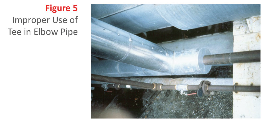
What is shown in Figure 5 is really an elbow, but a tee was used and a solid pipe was threaded into the tee to provide a pipe support. In this case, the tee provided an excellent heat transfer fin, which carried heat out of the insulated pipe onto an I-beam, which is an exceptional heat sink. In this minimum ambient temperature situation, the pipe froze because of the fin effect and the electrical heat tracing did not make up for the additional heat loss created by the jury-rigged pipe support.
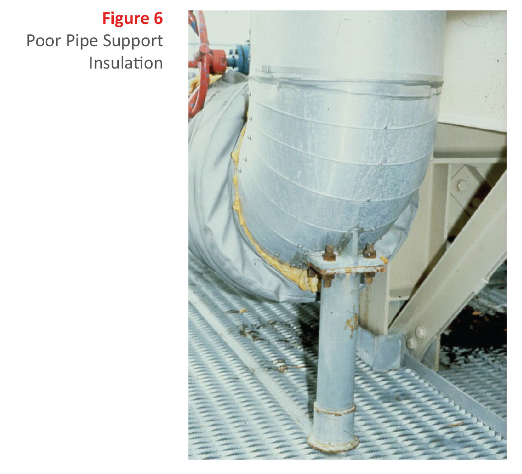
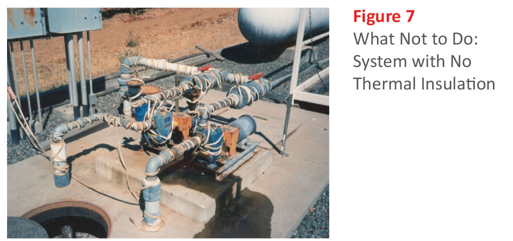
Figure 6 provides another example of poor pipe support insulation. You can see the extra insulation added outside the cladding because of extra heat loss. The uninsulated pipe support is a great heat sink.
Figure 7 shows an example of poor thermal insulation, or more specifically in this case, no thermal insulation. This example was observed at a winery where the pumping system provided wash water. Besides unnecessary energy use, (bare pipe = 10 watts per foot, fiber glass insulated pipe = 1.5 watts per foot), on a cold day with no clouds and excellent radiation to outer space (radiant cooling), the system froze.
Figures 8, 9, and 10 portray problems that took 4 years to rectify.
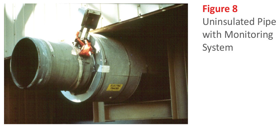
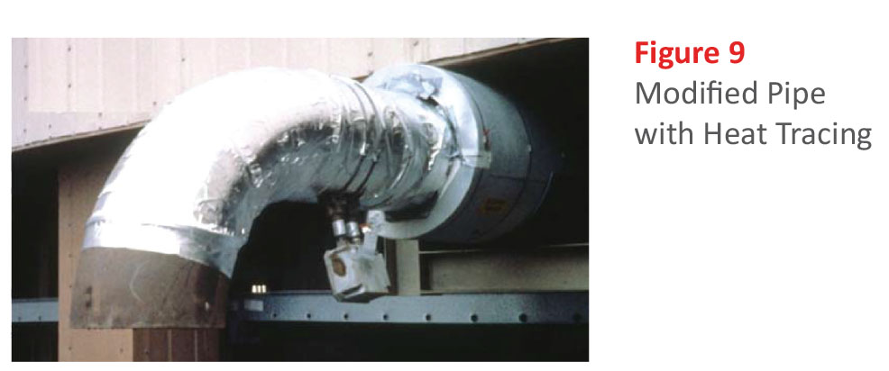
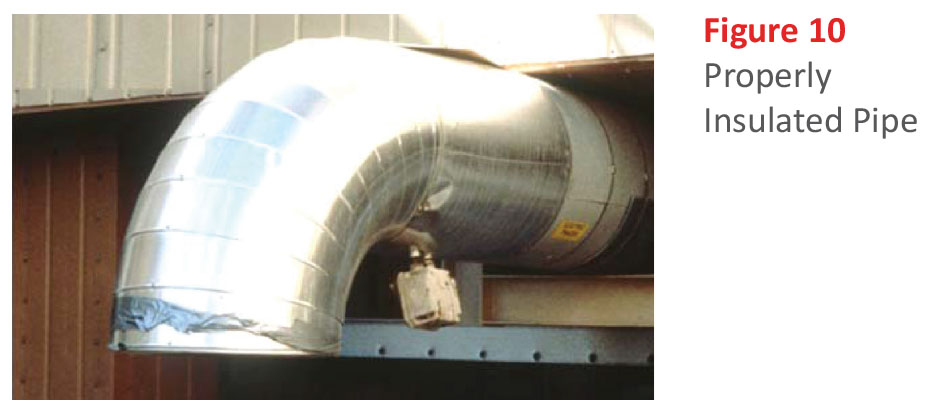
Figure 8 shows a 14-inch pipe that was the vent for a large tank (thousands of gallons). The electronics in the picture are part of a state-of-the-art power-line carrier monitoring system that sends the end-of-pipe temperature back to the Distributed Control System (DCS) in a North Slope of Alaska project. With the large uninsulated pipe exposed, the temperature of the pipe could never be maintained above freezing and eventually, condensate plugged the line. Snow also blew into the horizontal pipe. I was called to analyze the situation, and advised that more heat tracing was needed and the pipe should point down to prevent snow accumulation. Modifications were performed the next summer.
As shown in Figure 9, more heat tracing was added and an elbow pointing down was installed. However, the monitoring system still showed lower temperature than were required. When I returned to do an analysis, I recommended they insulate the new additional parts.
Finally, in the fourth year, the system was operating correctly. We now had a system that did not collect snow, did not have a huge fin that was exposed, and the thermal insulation was correct (see Figure 10). Ultimately, the key to reliable heat tracing is proper thermal insulation.
Sulfur Heating Lines
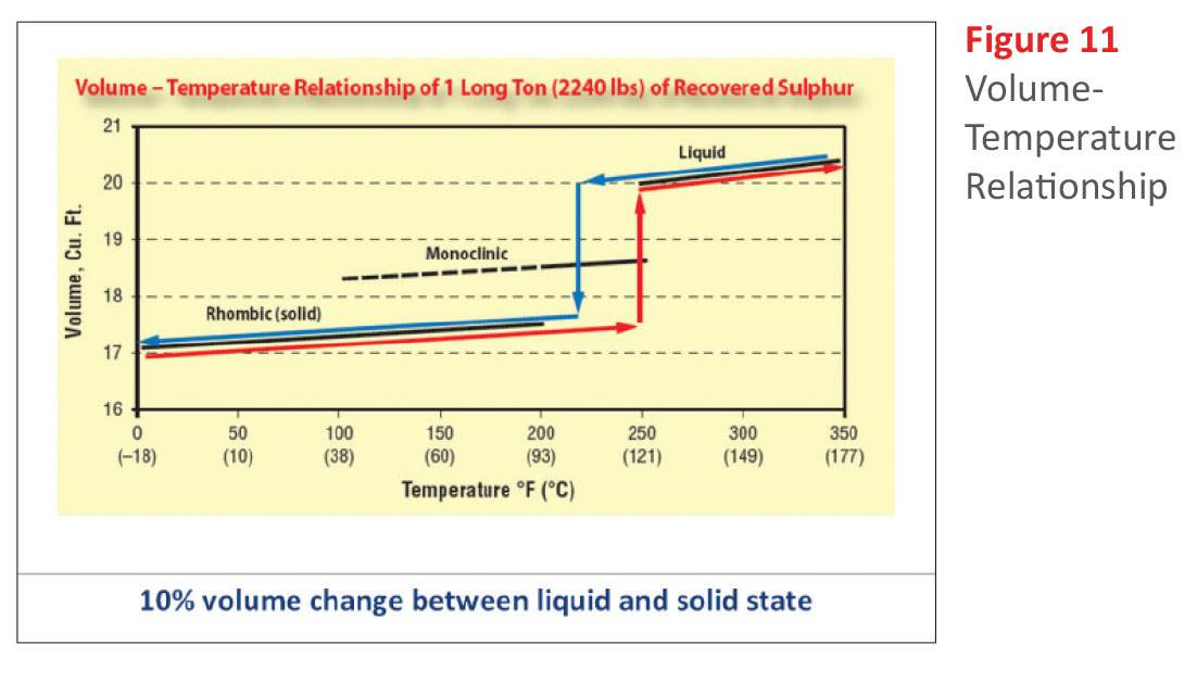
There are significant new technologies becoming available for the management of electrical heat tracing systems. One critical application is in sulfur pipe lines. The sulfur has both a lower temperature and an upper temperature requirement, with only a 20°C temperature tolerance band. At low temperature, sulfur is a solid, while at a higher temperature, it turns brown and is unusable as an industrial chemical (see Figure 11).
Oftentimes, sulfur pipeline electrical heat tracing systems are deployed that use Distributed Temperature Sensing (DTS). Current DTS technology uses a “glass fiber” with temperature- sensitive characteristics. An Optical Time Domain Reflectometer (OTDR) provides the temperature as a function of distance along the pipe. The electronics are expensive, but one set of electronics can service a number of pipe segments. The fiber reports back the temperature in approximately 2-foot increments. This gives the possibility of “tuning” thermal insulation at pipe supports and valves. After startup and before the sulfur is placed in the line, extra thermal insulation can be placed at the high heat loss areas such as the valves and pipe supports. The sulfur transport pipelines are long, sometimes reaching 450 kilometers. The addition of the DTS system with thermal insulation tuning shows a high-tech solution to old problems. As the price of DTS is reduced, more applications with electrical heat tracing are expected.
Thermal Insulation Is Critical
One of the basic requirements of an electrical heat tracing system is excellent thermal insulation. Anyone can go to a lumber yard and buy wood, but the quality of the project is dependent on the skill of the craftsman. The same is true of the electrical heat tracing system and especially the thermal insulation. Historically, steam has been used as a heat tracing system, and it was completely overpowering. However, maintenance, environmental requirements for condensate, and energy conservation have made steam less economical in some cases. Now electrical heat tracingwith an optimum balance between heat loss and heat suppliedis a preferred choice of many engineers, especially in arctic environments. The key to the system balance is reliable, dry, continuous thermal insulation.
References
- Institute of Electrical and Electronics Engineers (IEEE). “IEEE 515-2011 – Standard for the Testing, Design, Installation, and Maintenance of Electrical Resistance Trace Heating for Industrial Applications” IEEE, 2011.
- Jim Beres, Franco Chakkalakal, William M. McMechen, and Chet Sandberg, “Safer Sulphur Transfer,” IEEE Industry Applications Magazine, July/August 2006.
- P. Baen, M. Goodman, W.E. McBride, J. Rodriguez, “Training in the Use of Electrical Heat Tracing ‘a Course Outline'” Petroleum and Chemical Industry Conference, 1997. Record of Conference Papers. The Institute of Electrical and Electronics Engineers Incorporated Industry Applications Society 44th Annual Publication Year: 1997, 215223. Cited by: Papers (1)
- N.R. Rafferty and G. Tarbutton. “IEEE 844-2000: Recommended Practice for Electrical Impedance, Induction, and Skin Effect Heating of Pipelines and Vessels,” IEEE Transactions on Industry Applications 38, no. 4 (2002): 921-926.
- Chet Sandberg, “Heat Tracing System Selection,” Chemical Processing, November 1997, 65-71.
- Richard Huff and Chet Sandberg, “Design, Commissioning and Operational Experience of a Heat Tracing System with Extensive Electronic Monitoring” IEEE Transactions on Industry Applications 26, no. 6 (November/December 1990): 1070-1074.
- C. J. Erickson, N. R. Rafferty, J. D. Lyons, and C. L. Sandberg, “A Study of Steam vs. Electrical Pipeline Heating Costs on a Typical Petro-Chemical Plant Project,” IEEE PCIC Conference, Houston Texas, September 1990, PCIC-90-2.
- Chet Sandberg and Leonard Haile, “Fiber Optic Applications in Pipes and Pipelines,” IEEE PCIC Conference, Philadelphia 1985.
- Chet Sandberg and Henry Zylstra, “Ground Fault Circuit Breakers for Heat Tracing,” 1998 IEEE PCIC Conference, Indianapolis, Indiana, September 1998.