Understanding Thermal Systems: Basic Cooling Systems
Thermal energy (heat) flows naturally from high temperatures to low temperatures, and moving heat from low temperatures to higher temperatures requires work. There are a number of ways to accomplish this, but the most common method is the vapor-compression refrigeration cycle. The vapor-compression cycle is used in liquid-chilling equipment, direct expansion (DX) cooling systems, refrigeration equipment of all types, and in heat pumps. Insulation is an important component in many of these applications to either increase efficiency, control condensation, or in some cases, to control noise.
The commercial development of the vapor-compression refrigeration cycle is a fairly recent event. The first practical system was patented by James Harrison (a Scottish-born Australian) in 1856. By the 1890s, mechanical refrigeration was being utilized in breweries and meat-packing plants. In 1902, Willis Carrier (known as the “Father of Air Conditioning”) developed a system to control temperature and humidity in the Sackett-Wilhelms printing and publishing plant in Brooklyn, New York. The subsequent adoption of refrigeration and air conditioning was a significant contributor to our current standard of living and to the growth and development of our country. Refrigerated rail cars and trucks enabled the shipment of foods over long distances. Air conditioning greatly increased worker comfort and productivity during summer months, particularly in Southern cities. The importance of this technology was recognized by the National Academy of Engineering when they cited the development of air conditioning and refrigeration as one of the top 20 engineering achievements of the twentieth century.
The basic vapor-compression refrigeration cycle is used in a wide variety of systems and equipment. This ranges from small home refrigerators to large and complex commercial
refrigeration installations totaling thousands of tons of cooling capacity. Numerous home appliances utilize this technology, including refrigerators, freezers, air conditioners (home and automobile), dehumidifiers, and heat-pump water heaters. Larger-scale applications include cold-storage warehouses, food- and beverage-processing plants of all types, ice making, transportation systems (truck, rail, and marine), chemical and petrochemical processing, and natural-gas processing.
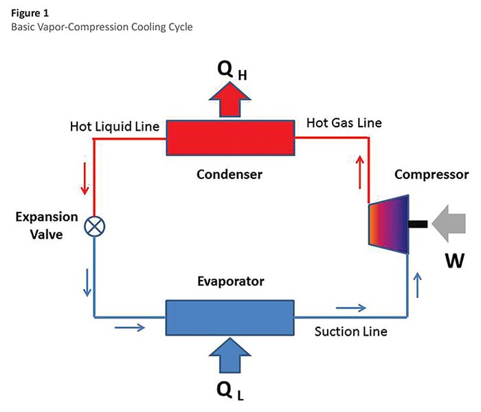
The basic vapor-compression cycle (see Figure 1) requires 4 components: a compressor, condenser, expansion valve, and evaporator. The compressor (usually powered by an electric motor providing the work, W) compresses the refrigerant to a high pressure and high temperature. The refrigerant then flows to the condenser, which is a heat exchanger where heat (QH) is removed (by air or water cooling) and the refrigerant is condensed to a liquid. The refrigerant then passes through the expansion valve where the refrigerant expands to a low pressure and a low temperature. The cold refrigerant then flows to another heat exchanger called the evaporator, where it absorbs heat (QL) and boils back into a vapor on its way back to the compressor. During its circuit around the system, the refrigerant picks up heat at the evaporator and rejects that heat (along with the energy added by the compressor) at the condenser.
Note that where cooling is desired (for refrigeration or air conditioning) the evaporator is located either within the cooled space or in duct work/piping systems serving that space. When heating is desired, the situation is reversed and the condenser is located in the heated space or in duct work/piping serving that space. In the latter situation, the device is called a heat pump or reverse-cycle refrigeration system. Many systems utilize a reversing value that can reverse the direction of refrigerant flow and allow the system to supply either heating or cooling to the same space.
The working fluid in this cycle is called the refrigerant. A wide variety of refrigerants are used in vapor-compression systems. Refrigerant selection depends on the application and involves many competing requirements. A primary consideration is the fluid’s thermodynamic properties (boiling point, latent heat of vaporization, specific heat, specific volume). Other important considerations include chemical stability, safety, environmental consequences, cost, availability, compatibility with compressor lubricants and equipment materials, and current regulations. Early industrial systems used many different working fluids–mainly ammonia, carbon dioxide, sulfur dioxide, or methyl chloride. In the 1930s, Freon® was developed by the DuPont Corporation specifically for use as a refrigerant and became widely used under the designations R-11, R-12, and R-22. These chlorofluorocarbon (CFC) and hydrochlorofluorocarbon (HCFC) refrigerants have been largely phased out due to concerns over atmospheric ozone depletion and global-warming potential. Alternative replacement refrigerants are now commonly used (R-134a, R-410A), and new refrigerants are under development.
The vapor-compression cycle uses mechanical energy (at the compressor shaft) to move thermal energy from a low temperature to a higher temperature. The efficiency of any conversion process is expressed as the ratio of the output (the energy sought) to the input (the energy that costs). For the vapor-compression cycle, the efficiency is often expressed as the coefficient of performance (COP). For a cooling system, the objective (energy sought) is the energy absorbed at the evaporator (designated as QL in Figure 1). The energy that costs is the work done at the compressor (W in Figure 1). The coefficient of performance is therefore QL/W (expressed in consistent units). For a heat pump, the energy sought is the heat rejected at the condenser (QH), so the coefficient of performance is QH/W. The coefficient of performance for modern cooling systems is usually greater than 1.0. In other words, the amount of heat transferred to the evaporator is greater than the amount of work required. Large water-cooled centrifugal chillers used for commercial HVAC systems can have full-load COPs of around 6.0. In other words, the energy absorbed at the evaporator is 6 times the amount of mechanical work required. Expressed as a percentage, this is a conversion efficiency of 600%.
There are a number of other terms used to express the efficiency of cooling systems. For smaller unitary equipment, efficiency is often expressed as the energy efficiency ratio (EER). Units on the EER are Btuh/watt. For example, a 3-ton unit (36,000 Btuh) that draws 3 kW (3,000 watts) would have an EER of 36,000/3,000 or 12.0 Btuh/watt. EER can be converted to COP by dividing by 3.412 Btuh/watt (so an EER of 12.0 equals a COP of 12.0/3.412 or 3.52). A variation on the EER is the seasonal energy efficiency ratio (SEER). This term is intended to reflect the fact that at part-load conditions (i.e., cooler weather), the efficiency improves. The SEER measures the average performance of a cooling system over a cooling season.
For larger central systems, performance is sometimes expressed as the total electrical power drawn by the system divided by the cooling effect achieved, or kW/ton. This term is a little confusing since lower kW/ton values have better performance. kW/ton can be converted to COP by inverting and multiplying by 3.517 (i.e., COP = 3.517/(kW/ton).
The use of insulation on vapor-compression cooling systems will vary greatly depending on the application. Small installations using packaged equipment will require little or no
insulation. Large custom-built industrial refrigeration applications (where loads are remote from mechanical rooms) may require miles of piping requiring insulation.
As a general rule, the suction lines (which transport cold vapor back to the compressor) require insulation to control condensation and/or ice formation and to limit parasitic heat gains. Any heat gain to these suction lines will increase the amount of work required from the compressor. Hot gas lines on cooling systems generally do not require insulation since the object here is to reject heat to the environment. The obvious exception is where the hot gas lines are accessible by personnel and are warm enough for burns. Another exception would be where hot gas lines run through conditioned space where heat loss would add to the cooling load. Hot liquid lines typically do not require insulation since again the objective here is to reject heat to the environment.