Understanding Thermal Systems: Hydronic Heating and Cooling Systems
Last month, this column focused on duct systems used for HVAC in commercial buildings. This month we will discuss hydronic heating and cooling systems, and focus on the low-temperature, chilled-water, and dual-temperature systems. Hydronic systems circulate liquid water through pipes to provide heating and cooling to the building zones. Although some consider steam heating to fall into this category, we will cover steam systems in a future column.
Hydronic systems consist of an energy source (boiler, water heater, or chiller), along with the associated pumps and piping that connect the source to suitable terminal heat-transfer units located in the spaces. While some gravity-driven systems exist, the circulation for the vast majority of hydronic systems is provided by electrically-driven pumps. Insulation is used extensively on hydronic systems to limit heat flow and to control condensation (on chilled-water systems).
Hydronic systems have advantages due to their relatively low initial installed costs, low operating costs, and virtually silent operation. The main disadvantage of hydronic systems is that they do not address the ventilation requirements of building occupants. Also, humidity control is either absent or poor. Hydronic systems are often combined with air systems to address these disadvantages.
Hydronic systems are often classified by operating temperature. The ASHRAE Handbook1 identifies 5 categories:
| Low-temperature water (LTW) | < 250°F |
| Medium-temperature water (MTW) | 250°F to 350°F |
| High-temperature water (HTW) | > 350°F |
| Chilled water (CW) | 40°F to 55°F |
| Dual-temperature water (DTW) | LTW and CW |
The majority of systems found in commercial buildings are low-temperature (LTW) systems, chilled-water (CW) systems, or dual-temperature (DTW) systems.
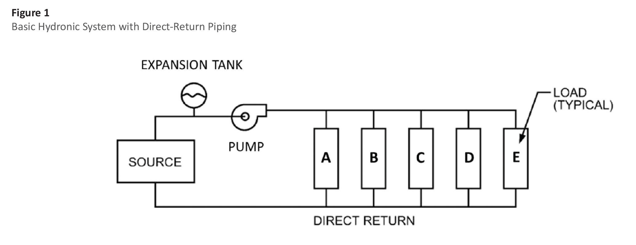
Figure 1 shows a basic LTW system consisting of (1) a source—in this case, a hot-water boiler, (2) a circulating pump, (3) heating coils located in the spaces served, (4) the piping connecting the devices, and (5) an expansion tank. The purpose of the expansion tank is to allow for the volumetric expansion and contraction of the water due to temperature changes in the system and to maintain the required system pressure. Although the expansion tank is not directly in the flow path, it is typically insulated to the same level as the piping to minimize heat loss/heat gains to the system.
Piping
Piping is generally made of either steel or copper. Steel is typically less expensive and is used for sizes over 1 inch. Copper is more expensive but is favored for smaller sizes due to its ease of installation. Piping systems may be laid out as either direct-return” or reverse-return” systems. A direct-return layout is shown in Figure 1. The disadvantage of this direct-return system is that the lengths of the flow paths (and hence the flow resistance) differ for the various terminal units. The flow path through Unit A is significantly shorter than the path through Unit B. The flow rate will be higher through Unit A. The same is true for Units C through E. The flow rates will be different in all the units, and that is undesirable. Balancing valves must be added to allow for balancing the flow after the system is installed.
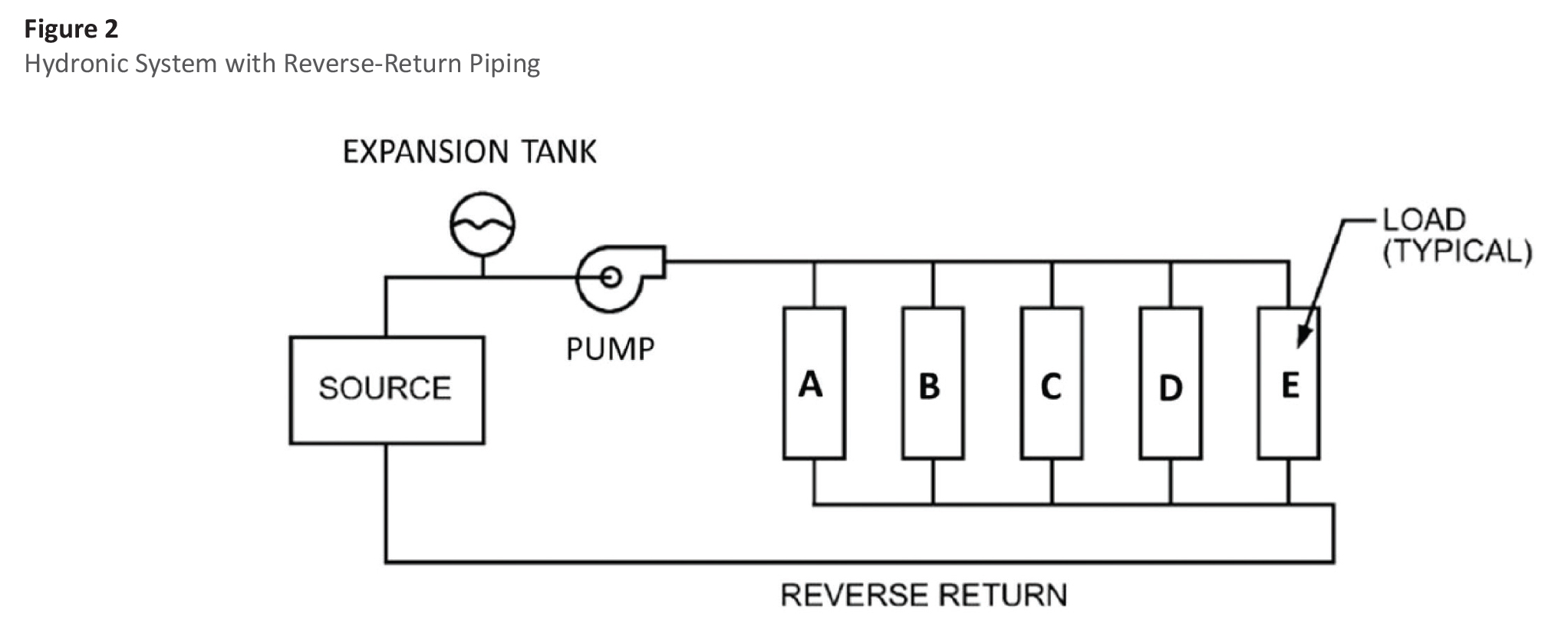
A similar system laid out with reverse return is shown in Figure 2. The advantage of a reverse-return system is that the flow resistance for each of the individual flow paths is roughly equal, so the system is essentially self-balancing. The reverse-return piping system is more costly, due to the additional length of return piping required, but is often justified where flow control is critical.
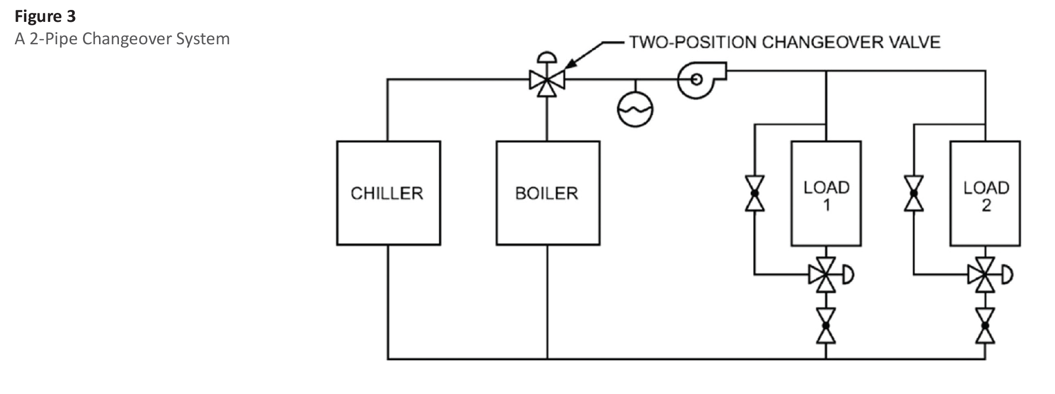
For hydronic systems that provide both heating and cooling, the distribution system may be configured as either a 2-pipe system or a 4-pipe system. A 2-pipe system is shown in Figure 3. Here, a single piping loop is used to supply either chilled water during the cooling season or hot water during the heating season. For this system, the operator is responsible for choosing a day when the system is changed over from cooling to heating (and vice versa). This means that during intermediate seasons, some spaces will be excessively cool while others will be too warm.
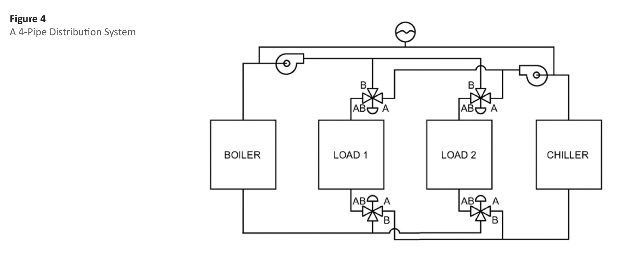
The alternative is a 4-pipe system (Figure 4), which gives the operator the ability to circulate both hot water and chilled water during intermediate seasons. Four pipes (2 supply and 2 return) serve each of the terminal units. The system is more expensive, since the amount of piping is roughly doubled, but overall occupant comfort is greatly improved.
Insulation for hydronic piping is required by most building codes. The 2015 International Energy Conservation Code (IECC) requires insulation thicknesses between 1/2″ and 1″ for chilled-water lines below 8″ nominal pipe size (NPS)—depending on operating temperature and pipe size. For hot-water systems operating below 200°F, the 2015 IECC requires insulation thicknesses between 1″ and 2″. Most codes include an exception for those piping locations where heat gain or heat loss will not increase energy usage. For example, a piping run through a heated space to a unit heater would not require insulation since any heat loss from the piping would help offset the heating load on the space.
A variety of insulation materials are used in hydronic piping systems. Mineral fiber insulation (fiber glass and mineral wool), with factory-adhered all-service jacket, is frequently used on both hot and cold hydronic piping in commercial buildings. Flexible elastomeric and polyolefin insulations without jacketing are also commonly found on hydronic systems. Polyisocyanurate, phenolic, extruded polystyrene, and cellular glass insulations are also used extensively.
Terminal Units
A variety of terminal units are used in hydronic systems, including heating/cooling coils in central air-handling units, zone or central reheat coils, finned-tube radiators, convectors, unit heaters, fan-coil units, radiant heating/cooling panels, and water-to-water heat exchangers.
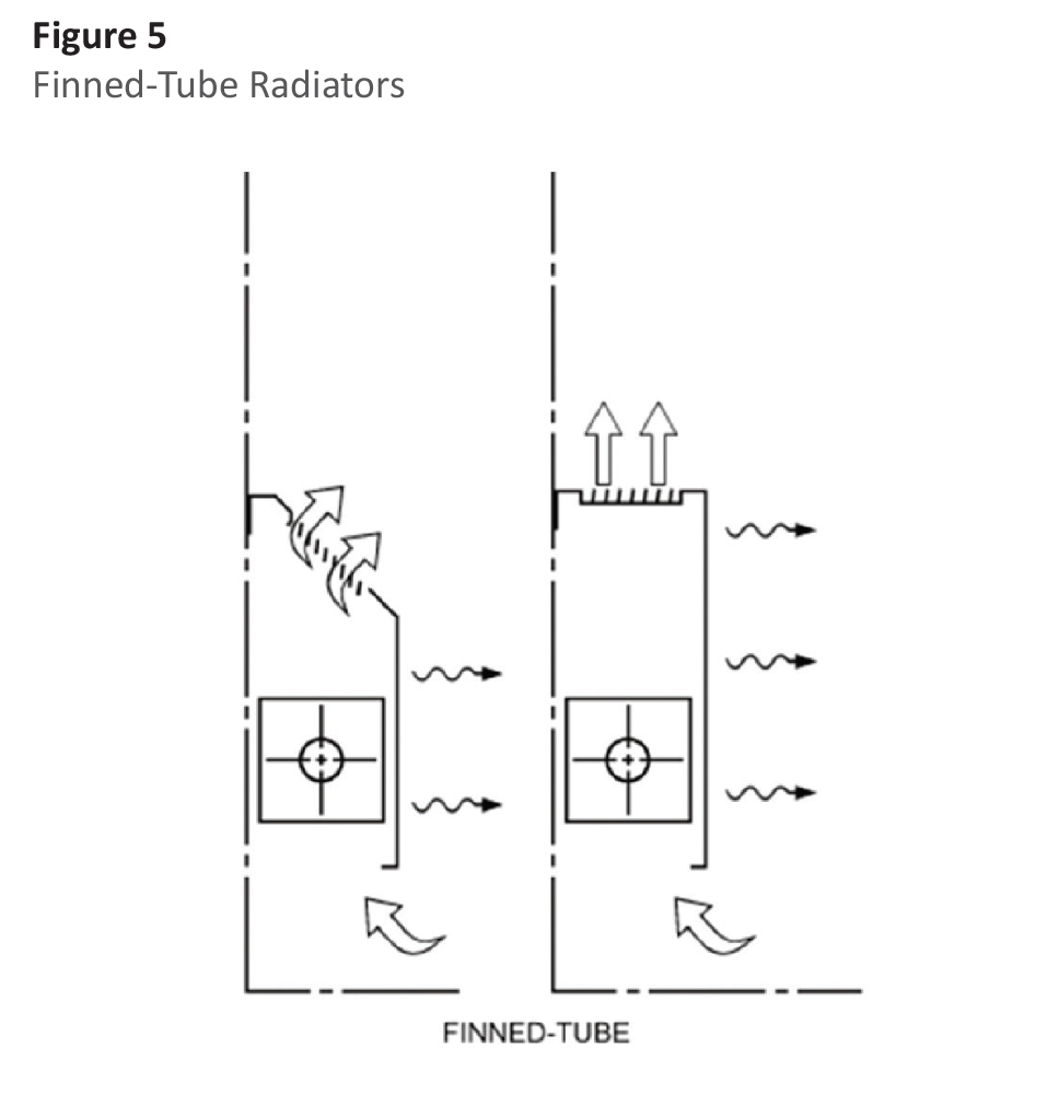
The simplest terminal units are finned-tube radiators (Figure 5). These are commonly used for heating around the perimeter of buildings. Local zone control is provided either by a control valve that varies the water flow, or, in some units, by adjusting an air damper to modulate the convective flow across the coils. Perimeter systems often utilize outdoor temperature reset, a control strategy that increases the temperature of the inlet water as the outdoor temperature falls.
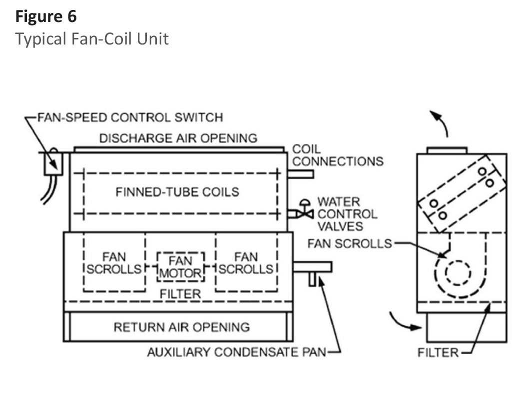
A typical fan-coil unit is shown in Figure 6. This device utilizes an electrically driven fan to circulate room air across the heating/cooling coils. Zone control is typically provided by a thermostat that varies the fan speed in response to zone load. Note that the figure shows 2 separate coils—one for heating and another for cooling—making this unit appropriate for a 4-pipe system. Some fan-coil units are located so that they may receive ventilation air from a penetration in the outer wall. Unit ventilators are similar devices, but are typically designed to provide up to 100% outdoor air to the space.
Pumps
A variety of pumping arrangements are used in hydronic systems. Single, constant-speed, centrifugal pump systems are common in smaller installations, but multiple pump installations provide redundancy in case a pump fails or is taken out of service for maintenance. Pumps may be installed in parallel or series configurations. For parallel configurations, the pumps are equipped with check valves to prevent recirculation through the off” pump. Variable-speed drives are becoming economical, allowing closer matching of pump operation to requirements. Pumps are commonly insulated to the same level as the piping using a fabricated-box approach or with removable/reusable covers to facilitate maintenance.
Reference
- 2012 ASHRAE Handbook—HVAC Systems and Equipment. ASHRAE, 1791 Tullie Circle, Atlanta, Georgia.