Using the MICA Manual (7th Edition) to Simplify Project Planning and Execution
The Midwest Insulation Contractors Association
(MICA) recently released the 7th Edition of the National Commercial
and Industrial Insulation Standards, often called the MICA Manual. This guide
is a definitive source of technical information for the design, specification,
and installation of commercial and industrial insulation. Many engineers use
the manual to help them document and outline exactly what needs to be done on a
project. In turn, contractors use the MICA Manual in their submittal packages
to convey insulation information and installation plans to the mechanical
engineer and help eliminate large punch lists of items the engineer flags as
incorrectly installed. Taking the guess work out of a project for both
engineers and contractors helps in project planning and minimizes problems and
delays in execution.
Using
the MICA Manual can save contractors time and money by giving a detailed
explanation of the materials and installation process to the engineer, who can
identify anything he or she may want done differently. For engineers, using the
MICA Manual in the submittal process offers the opportunity to communicate
easily with contractors and installers, preventing miscommunications and
streamlining the building and installation process. Fixing and rebuilding
aspects of installation can be very costly. It is much more cost efficient to
prevent errors than to attempt to fix them after they occur.
Using the MICA Manual to Create Your Submittal
Package
The easiest way to develop a submittal package is
to use the digital version of the MICA Manual, which allows users to input
information directly into the program and then print or send the filled out
“plates.” (Visit the MICA site at http://tinyurl.com/l6zbkln to purchase
the digital edition of the manual.) The MICA Manual plates are drawings of most
insulation applications with installation descriptions. These plates can be
populated with the appropriate text to give a complete description of how the
insulation installation is to occur. Using the digital version, you can
identify the insulation plates needed for a project.
The following example
illustrates a typical commercial insulation project.
Step 1: Develop a cover sheet describing the insulation
system.
Company: NIA
Contractor Member
Project: XX
Insulation System Materials per system. Refer to attached MICA plates for installation.
- Domestic hot and cold water piping and fittings:
XYZ flexible elastomeric pipe insulation, 3/4″ thick for all sizes. - Heating
hot water piping: XYZ fiberglass pipe insulation with ASJ, 1½” thick for all
sizes. - Heating
hot water piping fittings: XYZ PVC fitting covers with flexible fiberglass
inserts. - Concealed
supply ductwork: XYZ fiberglass blanket insulation, 1½” thick, type 75 with
FSK. - Exposed
supply air ductwork: XYZ fiberglass board, 1½” thick, 3 lb density, with ASJ.
Step 2: Once the cover letter has been
developed, the next step is to choose the corresponding MICA Manual plates and
download these plates onto a computer. It may be helpful to create a special
folder—e.g., named “Submittal Data”—to store these plates for future use on other
projects.
The following plates are needed
for this example:
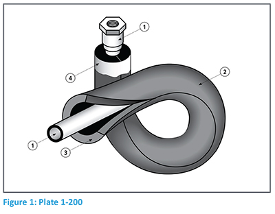
- 1-200
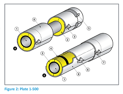
Flexible Foam Pipe Insulation - 1-500
Pre-formed Pipe Insulation Multiple
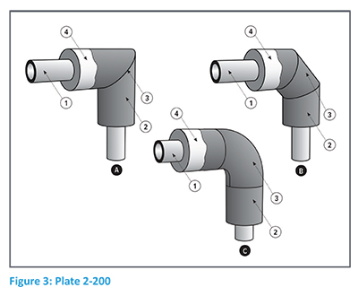
Layer Construction - 2-200
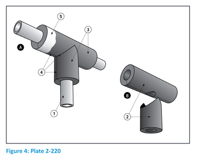
Flexible Foam Fittings: 90s and 45s - 2-220
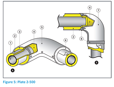
Flexible Foam Fittings: Ts - 2-500
PVC/Mineral Fiber Elbow Insulation System - 2-520
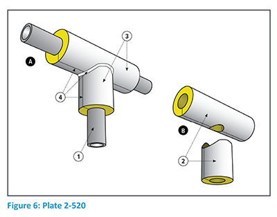
Field-Fabricated T Insulation - 3-100
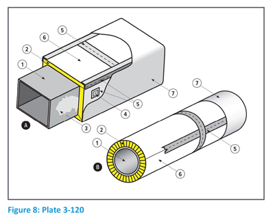
Flexible Fibrous Blanket Duct Insulation - 3-120
Rigid Board Wrap Around and Pre-Formed Duct Insulation (Exposed)
Step 3: To populate the plates with text,
download each plate to your desktop and click on the blue screen under the
“Submittal Data.” Type in the information for the project. Make sure the data
corresponds to the text and numbers listed in the upper half of the MICA plate.
Also, if there is a line item in the text on the plate that is not applicable,
list it as N/A (not applicable).
Step 4: As you complete each plate, save it
to the submittal folder that you set up for your project.
Populated Plates
The following 6 illustrations are examples of
populated plates for project ABC.
Once the plates have been
completed, save them to the submittal folder previously created. The next step
is to save the manufacturers’ product literature and the material safety data
sheets (MSDS) to your project folder.
Completing Your Submittal Package
The submittal package for the project is now
complete and clear for anyone involved in the project. The benefit of saving
the populated MICA plates is that they can be revised and used for the next
project, with appropriate adjustments for the new project and material
thicknesses. This not only simplifies the submittal process, but also adds to
your professional consistency.
The plates allow the project
engineer to see exactly how the insulation system will be installed. After the
engineer approves the submittal package, it is a comprehensive document that
describes the insulation system; the thickness of material; and the
installation of the material in a simple, step-by-step method. It can remove
the need for excessively long and complicated specifications that may be
difficult for different parties to translate.
The final step is to provide a
copy of the approved MICA plates that describe the installation process to the
project foreman. Instruct the foreman to install the insulation per the
approved MICA plates. This, too, can significantly decrease communication
issues and result in smaller or nonexistent punch lists.
The MICA Manual Puts Everyone
on the Same Page
With the use of the MICA Manual, the difficulties
of communication that often occur between the project engineer and insulation
contractor can be eliminated by creating a collaborative and simplified
document that ensures everyone is on the same page.

