What the Power Industry Should Know about Cyclone Boilers
A cyclone-fired boiler is designed to burn crushed coal to generate electricity. It is just one of many boiler types designed to burn coal. Coal-fired boilers generate over 55 percent of U.S. electric power. The boilers with the highest capacity (by megawatt) are designed to burn either pulverized coal (PC) or crushed coal. The PC-fired boiler has the distinction of being the most popular. The cyclone boiler has the dubious distinction of having the highest burner maintenance cost per year of any coal-fired boiler. Typically, a cyclone burner costs a power company approximately $75,000 annually to repair pin studs and refractory loss. With approximately 500 cyclone burners in operation, this equates to over $37 million or about 20 percent of the cyclone boiler industry’s annual maintenance budget.
Power companies value lower maintenance cost and generating electricity. For the cyclone boiler, this means reducing pin studding and refractory loss inside their cyclone burners. To do that, it is helpful to understand what makes the cyclone boiler so unique and hostile to refractory and pin studs.
A cyclone-fired boiler uses large crushed coal particles (typically 4 mesh size), which must be burned at a slower rate than PC1 to complete the combustion process. This slower rate of combustion requires a unique burner design.2 The burner’s assembly is a long, round chamber (6- to 10-ft. diameter) formed by water wall tubes attached to the outside of the boiler’s furnace wall. A cyclone burner assembly is best described by its three basic parts:
- Burner rear closure area, at the back farthest from the furnace opening, which ignites the coal by using oil or gas
- Barrel area, where the coal and air are mixed in a swirling or “cyclone” action and combustion takes place
- Re-entrant throat area, where the fire from the ignited coal is forced into the furnace area of the boiler
Unlike a PC-fired boiler, burning coal in a cyclone burner creates extensive amounts of slag and requires up to 10,000 lbs of refractory and thousands of pin studs. The refractory and pin studs are needed to protect the tube wall surfaces from the swirling (or cyclone) action of the coal and from the slag created when the coal is burned. The longer the refractory lining and pins studs stay in place, the longer the cyclone boiler can remain in operation.
On average, power plants get 1 to 2 years of refractory and pin stud life inside their cyclone burners. Historically, power plants getting 2 years between repair outages find that what looked like refractory on the cyclone burner walls was really just a layer of slag covering bare cyclone tubes.
For years, the cyclone boiler industry has been asking for better refractory that will extend their boiler operating time. Unfortunately, there is no new refractory that can protect the cyclone burners that way.
How can power plants extend pin stud and refractory life?
The answer might be found in the steel industry, which uses electric arc furnaces. These furnaces use electricity and reach temperatures similar to those inside a cyclone burner. Their walls are formed using studded, water-cooled tube panels and have no refractory. The steel industry has figured out a way to form a “frozen” layer of slag over the panels. This frozen layer protects the panels from the molten steel.
Another answer may begin with a better understanding of how the cyclone burner was originally designed in 1941. Historical data shows that the basic design of the cyclone burner was based on the following concepts:
- The refractory protects studs and tubes from the corrosive nature of the slag created by burning crushed coal.
- The refractory must follow the contour of the tubes and be installed approximately 1/8 in. to 1/4 in. over the top of the pin studs.
- The combination of pin stud quantity and the insulating value (K-value) of the refractory will cool the surface of the refractory at the hot face to a desired temperature where the slag will form the “frozen” thin layer of slag.
- The frozen slag formed at the hot face of the refractory will allow the balance of molten slag to remain molten and flow over the frozen layer and out the slag tap hole.
Based on the 1941 theory of design, the original manufacturers selected a very dense plastic chrome ore material that had a K-value of around 12 and a pin stud pattern of 384 pin studs per square foot for their cyclone boilers. It required a pneumatic hammer to ram the material into place and could be installed to follow the contour of the tubes.
However, some critical changes have occurred since that original cyclone boiler was designed:
- The coal burned today is a cheaper grade that creates more slag and a higher corrosive environment.
- Most refractory materials manufactured today have high K-values (38-44).
- The pin stud quantities have increased in density, in some cases to 520 studs per square foot.
- The application of choice is now by gunning, or the shotcrete method, instead of ramming.
These changes have a dramatic effect on the development of the frozen layer and the longevity of the refractory and pin stud lining. First, use of pneumatic gunning does not allow the refractory to follow the contour of the tubes. When the refractory is installed by gunning, it creates a flat, smooth wall surface inside the cyclone burner. The filled-in areas between the tubes, called valleys, have a higher surface temperature than the surrounding studded tube areas, which inhibits the ability to create the desired frozen layer of slag (see Figure 2). In addition, the combination of increased pin studding and refractory materials with elevated K-values may be cooling the refractory at a higher rate, which may be preventing the slag from forming the “frozen layer” at the hot face of the refractory. Finally, with pneumatic gunning (the shotcrete method) it is difficult to control exactly how much material is applied over the studs. Any additional refractory material greater than 1/8 in. to 1/4 in. thick over the pin studs can potentially inhibit creation of the “frozen” layer of slag.
It is highly unlikely that refractory manufacturers will create a new refractory that extends the life of pin studs just for the cyclone burner industry. Therefore, a way to extend the life of pin studs is the frozen layer of slag formed by applying refractory to follow the contour of the tubes. Boiler manufacturers, power companies, and refractory manufacturers must work together to figure out the right amount of pin studs based on the K-values of today’s refractory materials.
Extending the life of the pin studs and refractory inside a cyclone burner takes a complete understanding of every aspect of the boiler?including coal type, slag and ash chemistry, and burner stoichiometry. Only by installing the refractory correctly and analyzing all these elements can the cyclone power industry re-establish or create the frozen layer of slag and extend the life of the pin studs and refractory.
Notes
1. A PC-fired boiler “pulverizes” coal to a very fine powder, typically 200 mesh.
2. A PC burner looks like a long probe, with the tip of the burner located just at the entrance of an opening into the furnace wall.
References
ASTM C64-72, “Specification for Fireclay Brick Refractories for Heavy Duty Stationary Boiler Service” (withdrawn 1983).
Norton, F. H. Refractories in the Generation of Steam Power (McGraw-Hill Book Company, 1949).
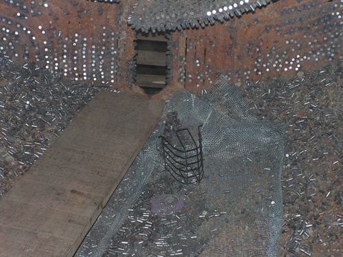 Figure 1
Cyclone burner restudding.
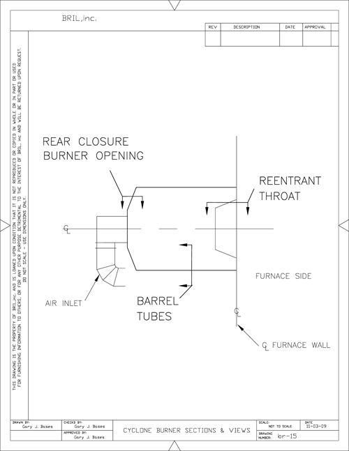 Figure 2
A typical cyclone burner key arrangement.
 Figure 3
Cyclone burner typical pin studding.
 Figure 4
Existing gunned refractory (note eroded areas in valleys).
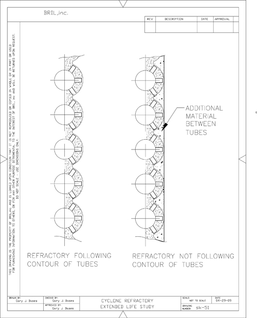 Figure 5
Cyclone burner tubes and valleys.
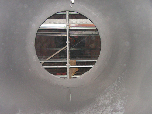 Figure 6
Cyclone re-entrant throat and barrel with refractory.