Insights for Insulation Installation
With the price for natural gas recently exceeding $9 per million Btu, and the price for a barrel of crude oil recently hovering between $25 and $40, the time may be coming when facility owners and operators begin recognizing thermal insulation’s significant role in reducing thermal energy use. This may take more time-and sustained high energy prices-for this message to hit home. You may recall that we experienced high energy prices in the first half of 2001, followed by a quick and dramatic collapse. A similar price drop isn’t likely to recur. If natural gas prices remain around their current level for at least a year, this pricing could start to have a profound impact on our attitude towards energy conservation, and in particular thermal insulation use.
Many people within the insulation industry have taken the National Insulation Association’s (NIA) Insulation Energy Appraisal Program (IEAP). In that program, students learn to use the 3E Plus® computer program to calculate heat energy loss or gain differences between insulated and uninsulated surfaces. Hence, students learn about the dramatic energy savings resulting from the correct use of mechanical insulation and the penalties paid by industrial facility owner/operators for leaving portions of their process piping and equipment uninsulated, either through neglect or design. Payback periods for insulating bare surfaces are typically a matter of months. The specific time is largely dependent on the price of energy used in the analysis. The 3E Plus program can also be used to estimate the economic penalty that results from insufficient insulation in piping and equipment. This program is free and available to the public by downloading from the North American Insulation Manufacturers Association (NAIMA) at www.pipeinsulation.org.
As is the case when evaluating the heat loss or gain differences between uninsulated and insulated surfaces, there are installation issues which can lead to excessive heat loss. Some of these, which can have a large impact on energy use, are:
- gaps at butt joints or resulting from less than adequate installation fit.
- wet insulation resulting from improperly fitted and/or caulked lagging.
- condensation on cold surfaces from insufficient design thickness required to maintain surface temperatures above dew point and/or inadequately installed vapor retarders.
- prematurely damaged or degraded insulation, either through vibration or some other external factors, resulting from less than adequate installation.
To avoid installation deficiencies, the owner/operator should also consider the benefits of requiring the insulation contractor to implement a formal Quality Assurance (QA) program, along with offering an extended warranty on the work. Finally, it’s worth considering the benefits of verifying insulation performance through the use of infrared (IR) inspections. This can be done shortly after facility start-up and some later time during the warranty period.
Increased Heat Loss from Gaps and Penetrations
If gaps develop at butt joints or other joints between adjacent pieces of insulation, then, in single layer jobs, the additional heat loss or gain can be excessive. As a simple rule of thumb for discussion purposes, the heat loss from a hot, bare surface can be about 20 times larger than from a surface insulated to industry standards. Therefore, if during plant operation, the gaps make up 2 percent (i.e., 1/50th) of the total surface, the heat loss or gain could be about 40 percent greater than what it would be without the gaps. For 36-inch long preformed sections of pipe insulation, 2 percent gaps translate to only 3/4 inch per section (this is during facility operation and after the pipes have expanded, not necessarily when installed on ambient temperature pipes).
Gaps of some sort can be the consequence of an inadequate specification, one which doesn’t require expansion/contraction joints (through the installation of a compressible insulation material in the butt joints between adjacent pieces of rigid insulation) or doesn’t require double layer on thick insulation applications. However gaps can also occur due to insulators simply neglecting to install the compressible insulation in those expansion joints, and from an inspector not catching the deficiency. Likewise, at insulation penetrations, such as at pipe hangers, supports, or other obstructions, gaps may occur during plant operation because of the contractor’s inadequate attention to installation details. Also, hangers and supports are a concern for higher heat loss, and should be at least partly insulated beyond the primary surface being insulated to prevent excessive heat loss.
Figure 1 is Plate #9 from the Midwest Insulation Manufacturers’s Association (MICA) National Commercial & Industrial Insulation Standards manual showing the correct way to install an expansion/contraction joint at pipe support rings by using a compressible form of insulation in that joint. Figure A, Segment 2 refers to the single layer pipe insulation and Segment 6 refers to the flexible fibrous insulation in the expansion/contraction joint. Likewise, for the use of a support ring shown in Figure B, Segment 8 is the steel support ring and Segment 9 is the flexible fibrous insulation used as a filler in that otherwise void space.
Wet Insulation
In outdoor applications, as well as some indoor applications in which the insulated pipes and equipment are frequently washed with spray water, there’s the potential for water to get into the insulation. This is, of course, avoided by a design specification requiring an adequate jacketing with sealing and caulking of lap joints, and water shields and other details at pipe hangers and supports. The difficulty of avoiding wet insulation is compounded by the "out of sight, out of mind" concept: if the jacketed insulation looks good, many owner/operators assume it to be performing as designed. To try to imagine the penalty to the owner/operator of an industrial facility, of operating his plant with wet insulation, let’s consider an analogy.
You’ve probably heard of people who celebrate New Years Day in Chicago by putting on their swimsuits and jumping into Lake Michigan. When these people get out of the water (probably very quickly, I might add) they have dry towels ready as well as dry, warm clothing. Now, try to imagine joining these people, except you will wear warm, well-insulated winter clothing, such as down ski attire, thick socks, gloves and a ski cap. Then you jump into the lake with them.
After getting out of the frigid lake, imagine standing around in the in the cold air or maybe taking a brisk walk up Chicago’s windy Michigan Avenue in the below freezing temperatures with this wet insulated clothing (though this isn’t recommended for those of us who value their health-simply try to imagine how you would feel!) In heat loss terms, your body would experience something similar to what the hot pipe with the wet insulation would experience. And that pipe, with the wet insulation, could operate in this condition for months or even years until the problem is identified and remedied. Yes, on a very hot pipe, it may dry out, but with tightly sealed, weather resistant jacketing, the outer portions of the insulation could remain wet.
It’s also in the owner /operator’s interest to assure himself that no wet insulation is installed. Therefore, it’s critical to pay attention to the manner of handling and storage, along with the weather, when installation takes place. If certain types of insulation are installed wet, there is a good probability that some will remain wet, even for a long time, following plant start-up. This situation can also be imposed on the insulation contractor by working on a fast track job in which the general contractor (GC) requires his subcontractors to work in wet weather, without protecting the insulation. It’s important for the owner/operator to make certain that fast track doesn’t include the GC’s schedule permitting the new insulation to get wet prior to installation.
The penalty for an industrial facility owner/operator to run his facility with wet insulation can be severe. The more wet insulation on a job, the more severe the excessive heat loss or heat gain problem is due to an increase in thermal conductivity caused water presence. It’s in the owner/operator’s interest to be certain that dry insulation is initially installed, and that the weather barrier jacketing is correctly installed, caulked, and sealed to keep the insulation dry for a long time.
Vapor Condensation on Chilled Piping and Equipment
Chilled piping and equipment that has insulation design thickness or inadequately installed vapor retarder will allow moisture to migrate to the chilled surfaces and condense. On surfaces with operating temperatures above 32 degrees Fahrenheit (F), it will result in moisture buildup on the chilled surface and in the thermal insulation itself. On surfaces with operating temperatures below 32 degrees F, the result will be ice and moisture build-up. As with insulation that becomes wet from rain due to an inadequately installed and sealed jacket, insulation that becomes wet from moisture condensation will conduct more heat to the cold surface than dry insulation. This means higher energy use by the owner/operator maintaining the cold fluid in the pipe or equipment.
Additionally, since a pound of water releases almost 1,000 Btu of heat energy to the cold surface, there’s an additional energy penalty beyond wet insulation. Finally, to add insult to injury, the water eventually can drip and lead to other surfaces becoming wet that aren’t designed to be wet. This is particularly a problem for chilled piping in buildings; condensation can lead to wet building materials, such as wood and drywall, which in turn can lead to their becoming damaged, possibly with mold growth.
To avoid these moisture condensation problems, it’s necessary that the owner/operator be certain that the insulation design thickness is sufficient to maintain the outside surface of the insulation above dew point, and that the installation is performed according to the specification. This means that the vapor retarder must be completely intact, whether through the use of tape, mastic, or whatever. Furthermore, the vapor retarder must not have holes, gaps, or other damage inflicted deformities. If a separate jacketing is installed after the installation of the vapor retarder, and damage has been done to the vapor retarder, then we have an "out of sight, out of mind" issue again until water starts dripping out of the insulation at gaps in the jacketing. The time to avoid this sort of problem is upfront, during original insulation installation, by installing the insulation and the vapor retarder correctly.
When closed cell foam insulation is used, it’s critical that the installer correctly seal all joints to prevent migration of moisture to the cold pipe or equipment surface. The water vapor transmission of closed cell insulation is low, but will only be effective with correct installation.
Another recently developed way to avoid these problems on chilled water lines is with properly installed, mineral fiber "wicking" type of pipe insulation system. While this allows moisture to migrate to the chilled pipe, it also provides for gravitational draining, wicking, and evaporation of the water. As with other systems, correct installation of the wicking system is required. It should be noted, however, that the "wicking" type systems are new and there’s a limited amount of published data on their performance. Time will tell whether they’re an improvement over conventional chilled water pipe insulation systems with a sealed vapor retarder or sealed closed cell foams.
Prematurely Damaged Insulation
and System Longevity
Certainly, no thermal insulation system can be expected to last forever. For example, some mineral fiber insulation boards on boilers can be expected to eventually settle, after many years of service, from vibration or temperature excursions. Another example: a hurricane that hits an industrial facility with insulated outdoor piping and equipment can be expected to tear off or damage some insulation materials. Most thermal insulation systems that are walked on regularly will degrade, regardless of their compressive strength (and some with low compressive strengths will degrade very quickly with foot traffic).
However, there are installation details that, if correctly adhered to, can assure mechanical insulation systems will last at least for the period of the warranty, if not for many years beyond, if the insulation isn’t physically abused.
For example, a well-written insulation system specification should identify the type and thickness of jacketing, the type, size, and spacing of attachment hardware, and the type, size, and spacing of banding. It’s in the owner/operator’s best interest to assure himself that these details are followed by the installation contractor according to the specification. Viewed from a distance, one insulation system with its system components that’s correctly installed, and another with a less than adequate installation, may look identical. However, a closer inspection will reveal the deficiencies of the latter.
While a hurricane or other excessively strong winds may damage an outdoor thermal insulation system, expected seasonal winds should not. If the specified jacketing is too thin, wind damage may cause bending of even a small part of the lagging; this, in turn, will likely allow rain access to the insulation, causing much greater heat loss or gain, as noted earlier. In addition, lagging of inadequate thickness will not provide adequate mechanical abuse protection expected by the owner/operator. Overall, it serves the owner/operator’s purpose to have an active instead of passive interest in the installation of his new mechanical insulation systems.
Achieving Quality Installation
To achieve a quality installation, owner/operators of industrial facilities, or their GC, should select an insulation contractor with a reputation for doing quality work. With many reputable NIA member contractors operating in different parts of North America, there are plenty of good choices. However, they should and can do more to assure themselves of a quality insulation installation. One important step they can take is to require that the contractor have, and implement, a formal QA program. We have heard increasingly in the last decade about formal QA programs such as ISO 9000. There are others, such as NQA-1, that in this author’s opinion, are equivalent to ISO 9000 if properly implemented. Whatever the program, it must have formal written procedures. Most formal QA programs have procedures addressing at least the following:
- 1. organization of both the company and the job site personnel
2. description of the QA program
3. review of customer’s purchase order(s)
4. control of customer supplied materials, parts, and components
5. purchasing of materials and services
6. control of document distribution
7. control of design
8. control of purchased materials, equipment, and services
9. identification of materials, parts, and components
10. control of special processes (typically welding)
11. inspections
12. handling, storage, packing, and shipping of materials
13. training of personnel
14. control and disposition of defective materials, parts, and components
15. corrective and preventative actions
16. control of QA and other project related records.
In general, the insulation contractor should have a quality assurance manager who has organizational freedom from the project management. The QA manager should report directly to a higher level of management, to someone who’s free from profit and loss responsibility for the particular project. The contractor should have an approved vendors’ list for purchase of materials and services, and a purchasing procedure to assure that correct materials are purchased, per the project specification. The QA manager should have a training program for the craftsmen, inspectors, and other personnel who affect the job quality. And, the manager should have inspection procedures for the particular insulation project, prior to, during, and after completion. Overall, the contractor should have procedures describing how the job’s performed. These procedures don’t have to be complex and lengthy. They should state what the contractor does, when it’s done correctly, and then it should do what his procedures say. It’s that simple.
Figure 2 shows insulation panels during installation. A good QA program would require a QC inspector to perform inspections using a sampling plan that represents some percentage of the insulation boards’ installation, prior to being covered with the metal jacketing. Once covered, it’s very difficult to evaluate the installation quality of the insulation boards other than with IR spectrometry.
Design is one element of a QA program for which an insulation contractor is generally not held accountable. The reason is the owner/operator (or designated representative, such as the engineer) is responsible for design, which includes writing the insulation specification. However, the insulation contractor always has some latitude in determining system details. If the insulation contractor were required to make assembly drawings calling out the details of the job, prior to starting the job, the overall quality could be improved by allowing the owner/operator to review those details and comment prior to start of the installation. The owner/operator will have to require the making of drawings of all bidders since it will obviously add some initial first cost to the job. However, in the end, it will pay for itself with greatly enhanced communication, improved attention to details, and, with updated (as-built) drawings at the end of the job, reduced cost for future insulation maintenance.
Overall, it’s in the owner/operator’s best interest to require the insulation contractor to have a formal QA program. And, the owner/operator should review and accept the contractor’s QA program prior to start of the job (and maybe even as part of the process of determining an approved bidders list). This will assure the owner/operator that the contractor has the self-monitoring capabilities to assure a quality insulation installation.
Post-Installation IR Inspection
After the contractor has completed the insulation installation and final inspections, but prior to plant start-up, the owner/operator or their design engineer should conduct his own physical inspection of the entire insulation job. After that’s completed and any necessary repairs are made, and following plant start-up, the owner/operator should conduct a thorough infrared inspection of the newly insulated piping and equipment.
While the owner/operator should obviously hire the services of a skilled IR technician to conduct the IR inspection itself, he should also hire a second person skilled both in the arts of thermal insulation and in examining IR photographs. This expert should accompany the IR technician to assure that all the relevant insulation surfaces are inspected, that the IR camera is correctly adjusted, and that the final IR results are correctly interpreted. The adjustment is necessary because an IR device simply detects surface temperature differences and therefore needs to be adjusted to detect differences of sufficient magnitude and thereby locate uninsulated surfaces, gaps, wet insulation, or other insulation deficiencies. The expert is necessary to differentiate between areas of poor insulation performance and areas with thermal bridging caused by heat loss through structural steel, the latter being unavoidable by the insulation contractor.
At one time, IR equipment was extremely expensive and cumbersome to use. However, today it’s much more affordable, there are many companies that can provide the services, and the equipment is relatively light and "user-friendly." With an IR camera, either still or video, the inspectors can make an IR record of the job.
If the IR inspections result in the detection of areas with high heat loss or gain and the expert determines that these are due to insulation deficiencies, then the insulation contractor should be required by contract to make repairs. Since such repairs can be expensive, it will obviously be in the best interest of the insulation contractor to make certain that his crew does a high quality original installation, per the specification. This means ensuring that his own QC inspector does a thorough inspection during and following the installation process.
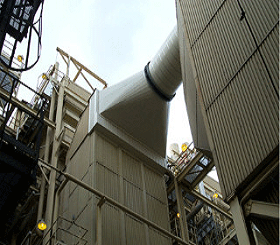
Figure 3 shows a section of a panel insulation system which appears to be in excellent condition. However, Figure 4, the corresponding IR photo, shows areas of high heat loss, either due to wet insulation or due to insulation gaps. In this case, the IR inspection reveals a serious insulation deficiency beneath the connection between the horizontal duct and the vertical panels. There, the surface temperatures are as high as 149 degrees F, whereas the general surface temperatures on the flat panels are only in the 50 degree to 70 degree F range.
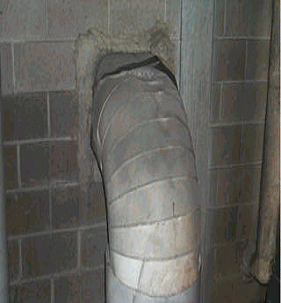
Another example of the power of IR inspections is shown in Figures 5 and 6. The former is a visual photo of an elbow. While the visual photo shows that there is some obvious physical damage to the metal jacketing, the degree of the damage isn’t revealed until you look at the corresponding IR image below. Note that the surface temperatures on the top of the elbow reach as high as 211.5 degrees F. While the IR photo doesn’t show the portions of the pipe below the elbow, you can see from the scale that there are insulation surfaces with temperatures as low as 92.9 degrees F. The high surface temperatures are an indication of areas with excessive heat loss, probably due to either wet and/or damaged thermal insulation beneath the jacketing.
Figure 7 is another example showing the successful use of IR thermography to detect areas of high heat loss, in this case on a horizontal, insulated pipe. While it’s not obvious what is causing the two areas of high surface temperature on the subject pipe, it’s clear that there’s something defective about the insulation material, either being wet, damaged, or incompletely installed.
There is a word of caution about using IR thermography. That is, this method doesn’t work well on new, shiny metal surfaces with low emissivity values (lower than about 0.2). Therefore, for new insulation systems, it may be necessary to wait several months prior to conducting an IR study. For an exterior job, exposed to the weather and to dust settlement, a year should be sufficient to increase the surface emissivity to 0.2 or above, allowing IR to be effective.
Warranty Benefits
To further assure that a quality installation is done, the owner/operator should require that the installation contractor provide a warranty for an extended time period. This should last at least 12 months and should include the obvious, such as installing the correct materials, materials of acceptable quality, per the specification, but also the less obvious, namely that the system performs per the specification for some period of time following installation.
For example, if the system’s jacketing leaks, resulting in wet insulation, without being caused by external damage to the jacketing or other in service abuse, then the installation contractor should be held responsible for the repair. Conversely, the contractor shouldn’t be held responsible for temperature excursions or physical abuse of the insulation caused by the owner/operator. These inspections, prior to the end of the warranty period, can be a combination of a physical inspection and an IR inspection. If the IR inspection detects areas of high surface temperature, then jacketing may have to first be removed to determine the nature of the deficiency (such as wet or deteriorated insulation, to name a few). Again, an insulation expert should be able to differentiate between an insulation problem and expected high heat loss or heat gain resulting from thermal bridging through structural members.
Taking an Active Interest
To assure a high quality installation of a mechanical insulation system, a facility owner/operator should take an active interest in the design and installation of the thermal insulation system. This should include the selection of a qualified insulation design specialist and a proven installation contractor. Part of the selection should include the insistence that the contractor has a formal QA program requiring the contractor to accept an extended warranty on his work, conducting inspections of the installation during the project and conducting a final inspection.
It’s further recommended that the owner/operator or his design engineer hire a qualified IR thermography technician and an insulation expert, and then perform follow-up physical and IR inspections at completion of the job and again prior to expiration of the warranty. This type of active interest on the part of the facility owner/operator can take comfort in knowing that not only has he purchased a quality installation, but also that the insulation system will perform as expected. He can thereby avoid high heat loss or gain problems caused by wet insulation (whether caused by leakage or condensation or prematurely damaged jacketing), gaps in the insulation, prematurely deteriorated insulation materials, or other avoidable deficiencies. The owner/operator and his design engineer should remember that many insulation deficiencies aren’t visible to the naked eye. They both must learn to look below the surface, preferably during and immediately following insulation installation, to determine whether those problems exist. In short, they both must take an active interest in their insulation systems.
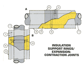 Figure 1
Installing an expansion/contraction joint at pipe support rings. (Used with permission from the Midwest Insulators Contractors Association, © 1999.
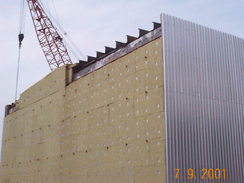 Figure 2
Ductwork in the process of being insulated, an opportune time for a quality control inspector to conduct an inspection.
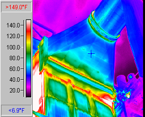 Figure 4
Infrared photo of the same panel system showing high surface below the connection horizontal duct.
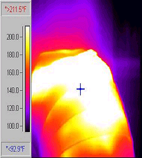 Figure 6
An infrared photo of the top of the same elbow as in figure 5 showing an area with high surface temperatures.
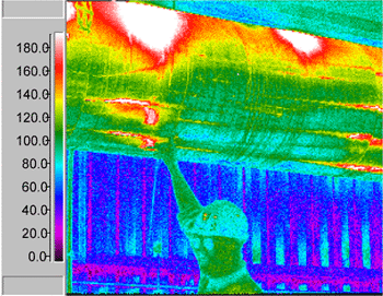 Figure 7
An insulated, horizontal steam line showing two large areas on the top surface with surface temperatures in excess of 180 degrees Fahrenheit, as well as some similar areas on the lower half of the pipe. Note that the well-insulated areas have surface temperatures in the 80 degrees to 100 degrees Fahrenheit range. Photo courtesy of Snell Infrared, Inc.

