Corrosion Under Insulation: The Inspection process
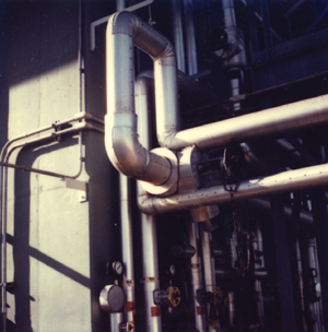
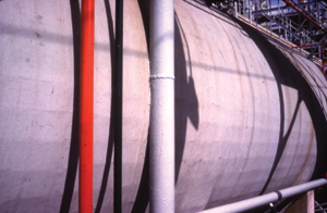
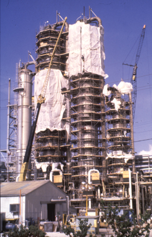
Corrosion under insulation has become more critical in the industry for a number of reasons. For one, the industry as a whole has become more complex. Chemical, petroleum and food processing facilities, to name a few, require more sophisticated equipment, instruments and piping arrangements (see figure 4). Piping and equipment are more difficult to insulate, requiring highly skilled professionals. Corporations are reducing their staff and their budgets. Cost cutting is putting inspections and maintenance in jeopardy.
These events can lead to a premature wet insulation system and eventually external corrosion to the pipe or equipment. Detecting corrosion under insulation (CUI) prior to serious damage or failure to the process system is imperative. With the current strict environmental laws, a process spill or failure can lead to legal ramifications.
Each year millions of dollars is spent in correcting the failure of pipe and equipment as the result of external CUI (see figure 15). This situation shouldn’t be surprising, since 95 percent of the failures go undetected until the product begins to seep through the insulation system into the ground or floor.
Reviewing Corrosion’s Principles
Before we discuss the inspection process of corrosion, it’s necessary to review corrosion’s basic principles. There’s no formula that will tell us actually the corrosion rate under insulation, but we do know that wet insulation systems accelerate the process. Uninsulated carbon steel and austenitic stainless steel can be exposed for years to all kinds of weather with only a noticeable film of surface corrosion on the substrate. Field testing to measure corrosion rate of various metals has been performed around the world under all types of environmental conditions. This information will tell us what materials corrode least under certain conditions, but they don’t tell us what happens under insulation in the same environment.
Insulation systems provide the perfect environment for corrosion promotion. The physical characteristics of insulation materials can vary widely. Some insulation materials contain a leachable inhibitor to neutralize the Ph in the water. Some insulation types may not be hygroscopic. All of these features should be considered when selecting an insulation material for a specific project. However, this may only delay the inevitable corrosive process if no periodic inspection and corrective action is taken. After a number of years investigating corrosion failures under insulation, it’s apparent that no insulation or insulation system is exempt from external corrosion to the substrate.
Fireproofing’s Contributions
Fireproofing materials must be included as a contributor to a wet environment that promotes corrosion. Fireproofing materials also function in part as insulation between the critical structural steel and a potential fire. Not only is fireproofing applied to structural steel on buildings, but also on support legs and skirts of vessels and tanks. The same consideration must be made for the wet carbon steel surface under the fireproofing material and corrosion prevention. Moisture can enter a fire proofing system just as it does with insulation systems.
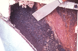
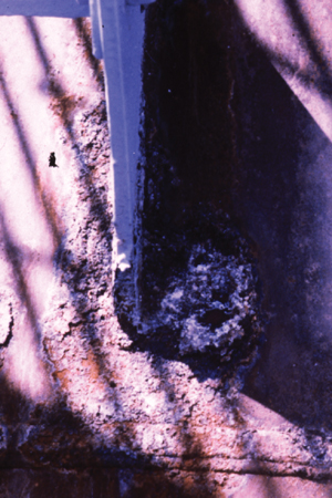
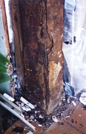
Several years ago, we removed fireproofing from structural steel columns on a building located near an ocean. We found that the steel columns facing the ocean had actually corroded so badly that removing pieces of rusted scale left unsafe supports. It only took a few years for the salt (sodium chloride) in the atmosphere to cause this catastrophic condition (see figure 16).
It must be assumed that every insulation and fireproofing system is subject to failure and thereby can promote corrosion. There are certain conditions that must be present. The insulation system must be exposed to moisture. The moisture may be created on a cold operating system by condensed vapor or it may simply be exposed to the weather. In any case, moisture must be present to induce corrosion.
Temperature/Corrosion Correlation
There may be a correlation between the operating temperature of the system and the rate of corrosion. At an operating temperature below 212 degrees fahrenheit (F) (100 degrees celsius [C]), the substrate may be constantly exposed to moisture. With a hotter operating system, the moisture will return to the substrate when the system is shut down for maintenance. This also takes place where there is a cycling process. This moisture is suspended in the insulation by an outer jacket that prevents it from evaporating, and a temperature above boiling at the substrate. When the operating temperature is reduced, the moisture heads for the substrate.
The definition of corrosion according to ASTM Standard G15-93 Standard Terminology Relating to Corrosion and Corrosion Testing is, "The chemical or electrochemical reaction between a material, usually a metal, and its environment that produces a deterioration of material and its properties."
General or uniform corrosion is when no particular location or area of the metal surface is more susceptible over another. However, what we usually see under insulation is localized corrosion. This area may have some special feature, a defect in the metal such as a crevice, or stress in the metal adjoining a weld line. This location becomes more susceptible to corrosion when enclosed in an insulation system. The geometry of the insulated pipe and equipment surface exacerbates the condition. They are complicated by interruptions where moisture can collect.
The two most common materials used for producing pipe and equipment in industry is carbon steel and austenitic stainless steel. Insulated aluminum and copper, both non-ferrous materials, can corrode as well, and require inspection per this article. However, we will limit our detail discussion to the most common materials.
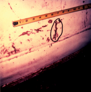
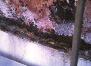
Corrosion to carbon steel (mild steel) usually is observed as pitting and eventually scales (see figure 6). This corrosion can occur at any temperature, which allows the moisture to accumulate on the insulated substrate. Sulfides and all types of chlorides are the leading contaminants in moisture, usually in the form of rain.
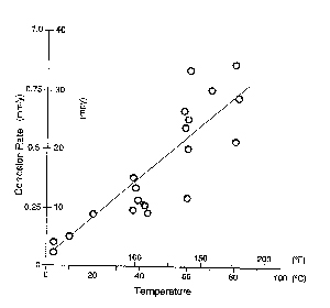
Oxygen is an important ingredient in promoting the electrochemical reaction for corrosion. Corrosion is substantially reduced on systems operating bellow freezing. Moisture in the form of ice reduces the oxygen from contributing to the corrosive activity. Generally, where there is water (aerated), there is oxygen. At a chemical plant site, a study was performed on the corrosion rate of steel under insulation. As the temperature of the wet carbon steel surface under the insulation rises, the corrosion rate increases. However, at temperatures above approximately above 175 degrees F (80 degrees C) the corrosion rate begins to decrease from a decrease of oxygen in the water (see figure 1).
Corrosion to austenitic stainless steel may be observed as intergranular, pitting or crevice, but the greatest offender is chloride stress corrosion cracking (CSCC). Solutions of magnesium, sodium, zinc, calcium, ethyl and lithium chlorides are some of the most aggressive of these.
The conditions to induce CSCC in insulated stainless steel are as follows:
- operating temperature between 120 degrees F (49 degrees C) and 300 degrees F (149 degrees C)
- oxygen to feed the electrochemical reaction
- water (domestic or rain)
- metal stress (caused be the fabrication process)
- austenitic stainless steel (non-ferric type- low in carbon)
Most CSCC failures occur when the operating temperature is between 120 degrees F (49 degrees C) and 300 degrees F (150 degrees C). Chlorides accumulate in a localized area from the continual migration of moisture containing the chlorides. The accumulation can vary from 1000 parts/million (ppm) to 20,000 ppm that can initiate CSCC. Depending on the geographic location, rain can contain from 75 ppm to 375 ppm chlorides.
Based on investigative reports for the past 20 years, there’s a direct relation between greater incidents of corrosion in highly industrialized areas in the United States. CSCC can happen on hot water or steam condensate lines or equipment.
Identify CSCC by random hairline cracks. The cracks will be irregular and difficult to see. Clean the surface to the bare metal. Then wipe a red food dye on the surface. Where cracks are present, the dye will be absorbed into the cracks, making them visible (See figure 5).
Stress is induced on any rolled pipe or formed equipment that has a cylindrical configuration. The shaping of the metal sets up the inner stresses. In addition, welding the metal sets up higher stresses in the weld area. Stress relieving the pipe and equipment would eliminate the potential problem, but the process is very costly.
Austenitic stainless steels, types 304L and 316L, are the most commonly used stainless steels in industry and are also susceptible to CSSC. The ferric stainless steels, 400 series, will be observed more as carbon steel, with pitting and crevice corrosion.
Galvanic corrosion has occurred where stainless steel is exposed to galvanized steel jacketing. It happens mostly on stainless equipment that’s insulated and jacketed with galvanized steel. This jacketing is more commonly used outside the United States and therefore this is where most incidents occur. The zinc chlorides leach out of the galvanized jacketing and work their way around and down to the equipment shell. Vertical equipment nozzles, located on the heads, provide the best avenue.
There’s only one way to determine that corrosion under insulation is under control. That is by setting up a proper inspection program.
Develop a checklist similar to the following:
- Identify those areas and/or processes on the site that have insulated pipe and equipment.
- Check the environment of the area where the insulated pipe and equipment is located. A field check is usually necessary. Rate the geographic areas by category (from category numbers 1 to 4). Mark a plot plan drawing or a sketch of the site.
1. the most critical conditions, where moisture is constantly present, and contaminants, such as acids, caustics and chlorides.
2. represents an area that’s only exposed to the weather (If the site is in a heavy industrial area and/or near the coast [salt water], it may be a category 1.)
3. an area that’s sheltered from the weather but may occasionally be hosed down.
4. indoors, in a dry area where only process or utility leaks are a consideration.
- Find some history of the insulation work and the age of the insulation system. Many companies have records and drawings that provide this information. Rate the age of the insulation by category, from A to C. Use this category as a suffix to the environmental categories.
A. an insulation system 15 years old or greater. (the life of an insulation system).
B. an insulation system 7 to 15 years old (system can fail in this age span if not maintained).
C. an insulation system less than 7 years old (shouldn’t fail if installed correctly).
- Identify the insulation materials on the pipe and equipment. Some insulation materials are more hygroscopic (retain moisture) than others. By identifying wet insulation, this will aid in the inspection for corrosion on the substrate. However, insulation may not be hygroscopic, such as cellular glass. Pockets of moisture may also exist between the insulation and the substrate non-hygroscopic insulation. This is why the identification of specific locations for inspection are critical since corrosion can be very localized.
- Determine the operating temperature of the insulated pipe and equipment. This information may also determine if the insulation system is wet and thus promoting corrosion. As noted previously, a hot operating system may prevent moisture from reaching the substrate, but this doesn’t mean that the insulation is dry. These systems should be inspected while they are shut down, to prevent a personnel safety problem. The inspector could be burned during the inspection process. While the process is operating, the inspector can determine the insulation surface temperature with an infrared instrument. The exact surface temperature isn’t critical, but a temperature above 140 degrees F (60 degrees C) should indicate poor thermal efficiency, which is usually caused by wet insulation.
First consideration should be given where the process temperatures cycle or the process is shut down for several months or more. The second area of concern should be given to operating systems in the range of 300 degrees F (149 degrees C) to 32 degrees F (0 degrees C).
Setting up areas and conditions by priority, the most severe can be identified for immediate inspection, while the least critical areas can follow.
For example: 1A on a plot plan or sketch will identify an old insulation system that has probably failed in an area constantly exposed to moisture and corrodents. This pipe and/or equipment require immediate inspection. This inspection program is only a guide. Users may wish to develop their own program to suit their particular requirements.
Inspection Location
The inspection process should be documented. Piping and equipment on chemical and petrochemical sites are currently inspected for internal erosion of the wall thickness by ultrasonic methods. Inspectors pinpoint certain locations on the pipe and equipment where the greatest erosion can take place. Likewise, we should perform the same procedure for the inspection of external corrosion under insulation and fireproofing. The inspections must be performed methodically with a time schedule.
The following identified locations are typical where wet insulation, the accumulation of moisture and, subsequently, corrosion can be found.
Insulated Piping
For insulated piping, inspect:
- at the bottom of the lower elbow on a vertical line.
- at the bottom or near tees for branch lines.
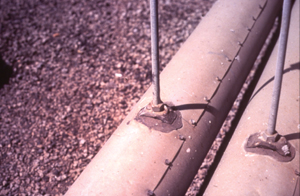
- at the bottom or near horizontal piping where instruments or pipe hanger supports protrude through the insulation system (see figure 12).
- at the bottom of horizontal lines where water or rust stains on the circumferential seams of the jacketing indicate that moisture had leached out from the wet insulation.
- above valves and flanges on vertical lines.
- at any break of the vapor retarder on cold lines, such as a line passing through a fire wall.
- any location where the degree of difficulty in applying insulation on pipe and equipment is high and therefore, failure is predictable (see figure 13).
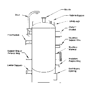
Insulated Vessels and Tanks (see figure 2)
For insulated vessels and tanks, inspect:
- on vertical vessels and tanks, above the intermediate insulation support rings (see figure 14).
- around the base of the tank, at the base plate, orienting the inspection 90 degrees apart (see figure 9).
- near large vessel and tank nozzles and manholes, especially where the insulation jacket has visibly shifted from the nozzle (see figure 10).
- at the bottom of horizontal tanks where water or rust stains on the circumferential seams of the jacketing indicate that moisture had leached out from the insulation.
- at the outer edge of the roof, orienting the inspection 90 degrees apart. (This depends on the design of the vessel and tank roof and the presence of an insulation support ring or angle.)
- under any structural steel legs for platforms, protruding through the insulation at the sidewall or roof (see figure 11).
- under protruding vessel nameplates.
Fireproofing of Structural Steel Columns and Vessel Skirts
For fireproofing of structural steel columns and vessel skirts, inspect:
- near the base of the steel column. (Be sure to inspect the web if it is a beam.)
- at the angular cross bracing attached to the column.
- at the skirt access opening on skirted vessels.
Inspection Procedure
Here are some inspection procedures to follow.
- Use non-destructive methods to inspect.
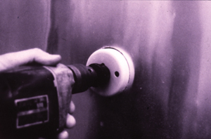
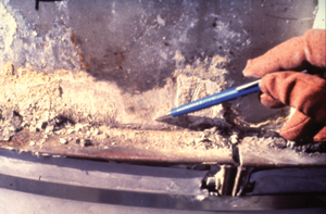
- Don’t proceed to cut or saw a hole in the insulation for inspection and seal it with duct tape or some other haphazard method. If the insulation is dry, you want to keep it that way (see figure 7).
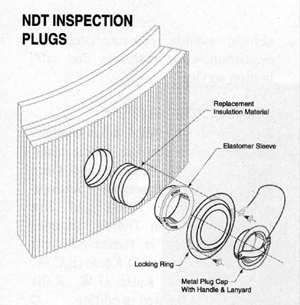
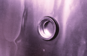
- There are a variety of NDT port assemblies to select from. These port assemblies will provide easy access for inspection on a periodic program. In order for the port assemblies to seal out moisture, they must be installed exactly in accordance to manufacturer’s instructions (see figure 8).
- Use the largest available size inspection port assembly for the application. They are generally available in sizes of 1-1/2 to 5 inches in diameter. For small piping the port size must be small but on large piping and vessels use a large port assembly. The larger port provides easier visual inspection.
- Before sealing the port, fill with the existing or new insulation. High-temperature blanket insulation is suitable for re-inspection purposes (see figure 3).
General Inspection Tips
- Develop a scheduled method of inspecting.
- Identify the physical characteristics of each insulated pipe system and equipment.
- For carbon steel, check for pitting and scaling.
- For stainless steel, check for stress corrosion cracking.
- Identify critical locations on pipe and equipment for inspection.
- Document the condition of the substrate, such as no corrosion, mild corrosion or severe corrosion.
- Document condition of the insulation, such as dry insulation or wet insulation. Schedule the replacement of wet insulation.
- Re-inspect on a yearly basis.
Where new insulation systems are to be installed, consider a proper coating system. This information on coatings can be found in NACE publication Standard RPO198-98 Item No. 21084 or by contacting the author of this article.

