A Different Perspective: High-Temperature Systems and Applications
The central building blocks of any new or existing steam-generating, fossil-fired boiler are the boiler island’s high-temperature systems. All high-temperature systems found at steam-generating facilities require insulation (and lagging) applications that, at minimum, keep the surface temperature at or below the boiler or equipment manufacturers’ designed heat loss (usually around 120-140°F). The insulation and lagging (and jacketing) systems for these high-temperature applications also must be designed to help keep installation costs down.
A high-temperature system is defined as any system operating above 350°F. For the power-generating industry, that would encompass the steam-generating boiler walls, penthouse or vestibule enclosure, economizer casing, wind box, secondary and primary air ducts, gas outlet flue to the air heater, air heaters (recuperative and regenerative), dust collectors, gas re-circulating flue, pulverizers, and air-pollution equipment installed before the air heater-such as selective catalytic reducers, non-catalytic reducers, scrubbers, and precipitators. Piping systems also can be considered part of high-temperature applications such as downcomers, steam leads, soot blower piping, supplies, and feed water pipes. For the power-generating industry, high-temperature applications amount to about 70 percent of the insulated area at any given power plant. Here are some typical examples.
Example 1
A typical 100-150 megawatt tangent tube design is usually covered on the outside of the boiler and furnace tube walls with 3″- or 4″-thick mineral wool-type board insulation and an outer aluminum lagging material. This type of steam-generating boiler has approximately 17,000 square feet of mineral wool board insulation meeting ASTM C612 type IVB and outer lagging on the boiler walls; 1,000 square feet of hard block type (calcium silicate type meeting ASTM C533), usually used on the penthouse (top of boiler)
roof and steam drum; and 1,000 linear feet of boiler-proper piping covered with either calcium silicate or mineral wool pipe cover insulation and jacketing (see typical piping systems and temperatures below).
- Drum and Pressure Parts 575°F
- Econ Inlet Header and Piping 462°F
- Econ Outlet Header and Piping 577°F
- Reheat Super Heater Outlet 1,005°F
- Reheat Super Heater Inlet 690°F
- Secondary Super Heater Inlet Header 710°F
- Secondary Super Heater Outlet Pipe 1,005°F
- Primary Super Heater Outlet Pipe 1,005°F
- Primary Super Heater Inlet Pipe 700°F
Example 2
A typical radiant-type boiler (500-600 megawatt) with a steam output of 3,700,000 pounds of steam per hour and a membrane tube wall construction is usually covered on the outside of the boiler and furnace tube walls with 4″-thick mineral wool-type board insulation and an outer aluminum lagging material. This type of steam-generating boiler has approximately 45,000 square feet of insulation meeting ASTM C612 type IVB and outer lagging on the boiler walls; 50,000 square feet of flues, ducts, and equipment with insulation meeting ASTM C612 type IVB; 4,000 square feet of block insulation on the penthouse roof (top of boiler) meeting ASTM C533 or ASTM C612 type V; and 3,500 linear feet of boiler-proper piping covered with either calcium silicate or mineral wool pipe cover insulation and jacketing (see typical piping systems and temperatures below).
- Econ Inlet Header and Piping 629°F
- Econ Outlet Header and Econ Discharge Piping 629°F
- Furnace Downcomer, Bottle, and Supply Tubes 629°F
- Primary Super Heater Inlet 650°F
- Primary Super Heater Outlet 800°F
- Secondary Super Heater Inlet 800°F
- Secondary Super Heater Outlet 1,015°F
- Soot Blower Piping 800°F
Example 3
A typical universal pressure-type boiler (1,300 megawatt) with a steam output of 4,400,000 pounds of steam per hour with a membrane tube wall construction is usually covered on the outside of the boiler and furnace tube walls with 4½”- or 5″-thick mineral wool-type board insulation and an outer aluminum lagging material. This type of steam-generating boiler has approximately 100,000 square feet of insulation meeting ASTM C612 type IVB and outer lagging on the boiler walls;150,000 square feet of flues, ducts, and equipment with insulation meeting ASTM C612 type IVB; 9,000 square feet of block insulation on the penthouse roof (top of boiler) meeting ASTM C533 or ASTM C612 type V; and 14,000 linear feet of boiler-proper piping, covered with either calcium silicate or mineral wool pipe cover insulation and jacketing (see typical piping systems and temperatures below).
- Econ Inlet Header and Piping 637°F
- Econ Outlet Header and Econ Discharge Piping 637°F
- Furnace Downcomer, Bottle, and Supply Tubes 637°F
- Platen Super Heater Inlet 907°F
- Platen Super Heatet Outlet 1,006°F
- Secondary SuperHeater Inlet 981°F
- Secondary Super Heater Outlet 1,115°F
- Final Reheat Super Heater Inlet 1,026°F
- Final Reheat Super Heater Outlet 1,126°F
- Primary Reheat Super Heater Inlet 705°F
- Primary Reheat Super Heater Outlet 1,026°F
- Primary Super Heater Inlet 794°F
- Primary Super Heater Outlet 929°F
- Pump Recirculation and Piping 637°F
- Vertical Steam Separator and Piping 900°F
- Arch Outlet Header 831°F
- Spiral Transition 772°F
- H2O Collection Tank and Piping 637°F
- Dilution Air Skid and Header 100°F
- BLR and FNC SB Piping PSH to PRV Station 902°F
- BLR and FNC SB Piping PRV Station to Soot Blowers 782°F
- AH SB Piping Platen Outlet HDR to PRV Station 983°F
- AH SB Piping PRV Station to Soot Blowers 903°F
- SH Attemperator Piping 637°F
- RH Attemperator Piping 533°F
Boiler Design
In the steam-generating industry, it is important to understand high-temperature systems and how to improve insulation practices within the boiler island area. The power industry requires smarter and more economical insulation designs on the steam-generating boiler walls-especially when considering the rising cost and reduced availability of qualified field labor. The potential cost savings with improved insulation practices is small compared to the total plant cost, but every dollar saved is important. It is up to everyone working within the steam-generating industry to find ways to cut cost without reducing boiler efficiency. This section describes one way to reduce labor cost.
Today, the power industry accepts the assertion that a double-layer application in lieu of one single layer of insulation on membrane boiler walls creates a better insulation system. In the past, that assumption was not always the case. Single-layer application on membrane boiler walls was a common practice within the power industry for many years. In fact, almost every boiler built in the United States between 1968 and the mid 1980s, regardless of manufacturer, specified single-layer application as the boiler wall insulation standard, unless the thickness required by operating and surface temperatures was greater than 4″. Double-layer application during that time was typically specified only when it was a special requirement by the end user, or the insulation material was not available in a single layer from the insulation manufacture.
All boiler original equipment manufacturers (OEMs) specified and documented the insulation thickness and material requirements on their steam-generating boilers. Each has developed company standards for the type of insulation and the acceptable application procedures for installing the insulation. These standards and application procedures are provided with each boiler sold, whether the insulation is in the OEM’s scope of supply or not. This practice is still true today.
It is interesting to note that the decision to use a single or double layer of insulation during the construction of the boiler is not tied to the boiler performance warranties. It does not matter if a single or double layer of insulation is specified. The total thickness is what governs insulation performance. The decision to specify a single layer over double layers was strictly an economic decision made by the OEM.
Single-thickness insulation has a long and successful history in the power-generation industry. During the period from 1964 (starting with the membrane tube wall construction) to 1990, one particular boiler manufacturer built and sold over 250 radiant power boilers, 150 universal pressure boilers, 200 industrial boilers, and 100 process/Kraft recovery boilers. All of these boilers were designed and constructed with a single layer of mineral wool board on the boiler walls, with 4 inches of insulation and a cold surface temperature of 130°F. Significantly, the OEM has not reported any problems meeting boiler performance caused by using a single layer of insulation on all of these units.
Costly Changes
In the mid-1990s, several OEMs and purchasers changed their insulation standard to require a double layer of insulation with the same overall thickness on their boiler walls. The reasons behind this specification change remain unclear to those of us who design and specify insulation systems for a living. If this change has its roots as an energy-saving decision, then one layer will perform as well as two layers at the same overall thickness, assuming the insulation is installed correctly.
Some argue that a double-layer application is better than single layer because it eliminates gaps between the individual insulation pieces and reduces the chances for hot spots on the outer lagging or casing surface. This is a labor supervision issue and not a design specification issue. Every OEM installation standard clearly states that gaps between boards or blankets are not acceptable, regardless of how many layers of insulation are installed. These standards require that all insulation be tightly butted against each other, and any gaps between insulation must be filled with appropriate insulating cement before the outer lagging or casing is installed. These standards are independent of whether the insulation is applied in a single or double layer.
Field inspections have shown that using a double layer of insulation has several drawbacks. First, the cost to use double-layer versus single-layer insulation on boiler walls increases the cost of materials (insulation and additional fasteners) and labor. For example, a boiler with 100,000 square feet of water wall surface covered with a 4″-thick double-layer mineral wool board meeting ASTM C612 type IVB, instead of a single board of the same thickness, raises the cost to build that boiler by approximately $200,000 and does not increase boiler efficiency or prevent any additional heat loss.
Secondly, going to a double layer often increases the number of gaps and can increase the incidence of improper insulation application. This situation takes place when the first
layer of insulation is installed in a shoddy manner, followed by a second layer that hides the poor craftsmanship. Unfortunately, this occurs all too frequently. Only good supervision will prevent this situation from becoming an epidemic on a job site.
Final Thoughts
High-temperature systems are found at every steam-generating facility. They require and demand thermally and energy-efficient insulation systems. The late J.P. Malloy, author of “Thermal Insulation,” noted something in 1969 that still holds true today: “Insulation installed to save energy also saves money at the rate that is essential for efficient plant operation.” A better understanding of your high-temperature systems and their required insulation designs, applications, and thicknesses will inevitably help save you money and avoid future installation problems that could potentially haunt your project for years to come.
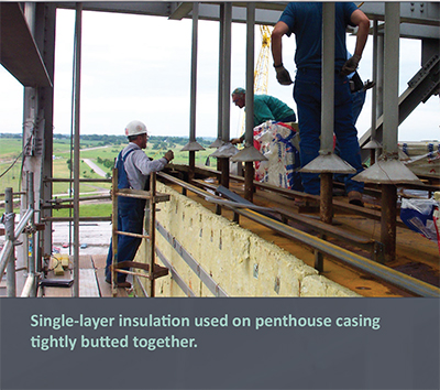 Figure 1
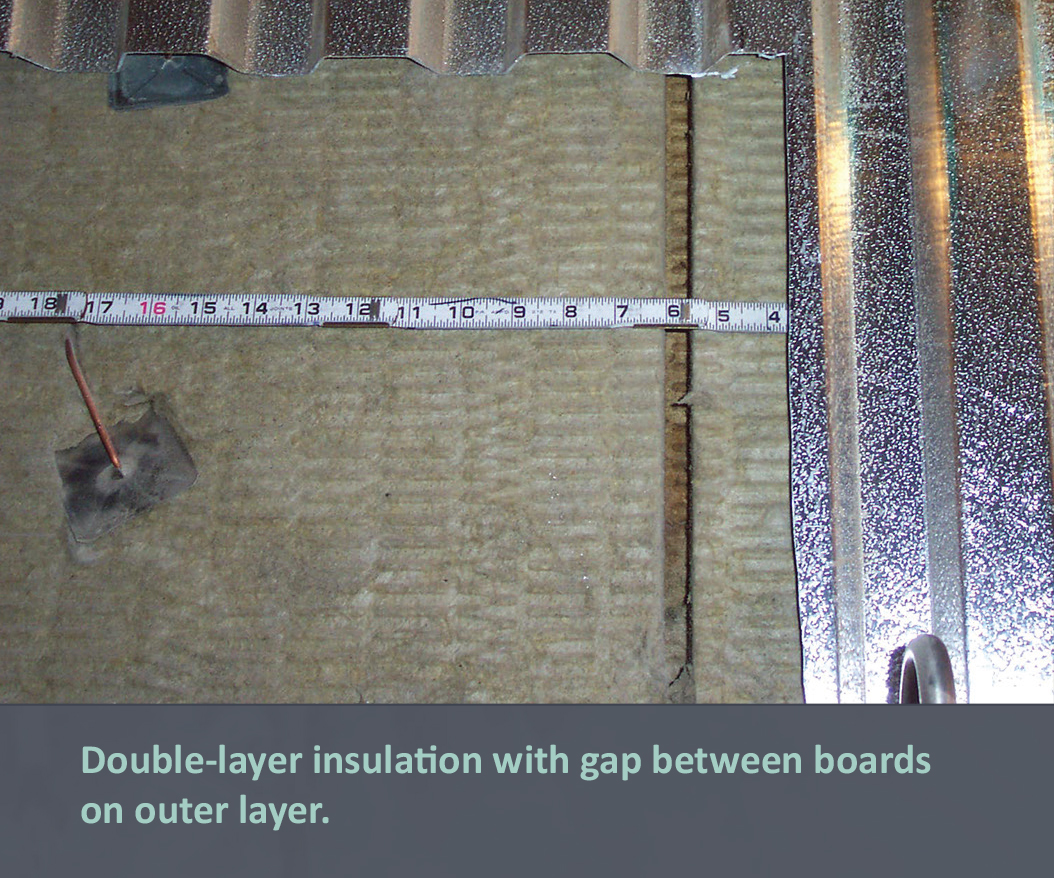 Figure 2
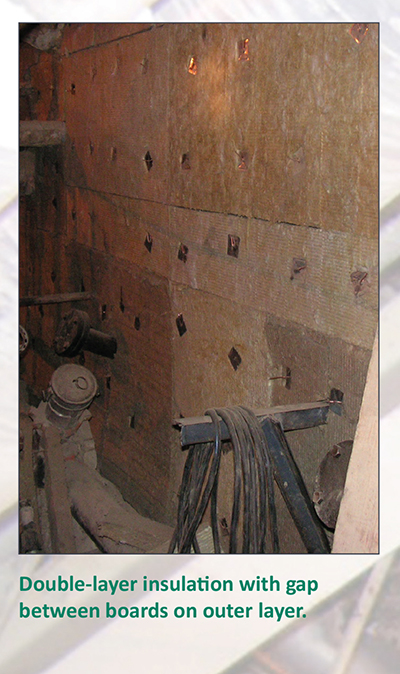 Figure 3
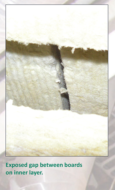 Figure 4
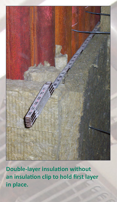 Figure 5
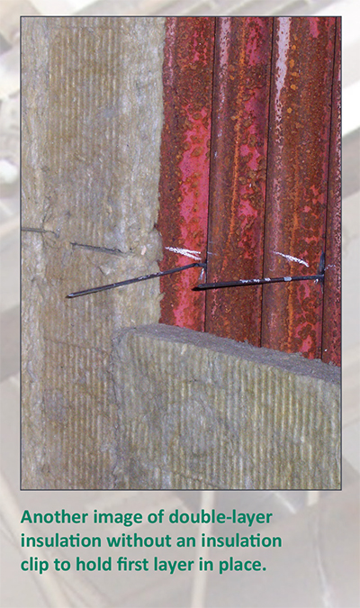 Figure 6
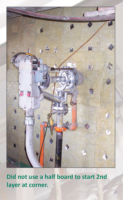 Figure 7
 Figure 8
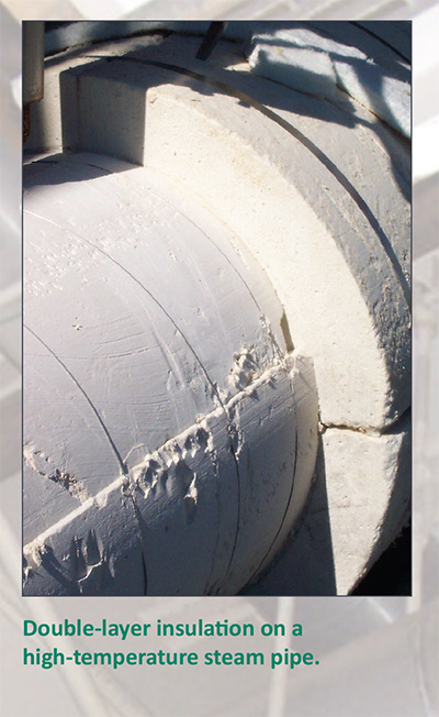 Figure 9
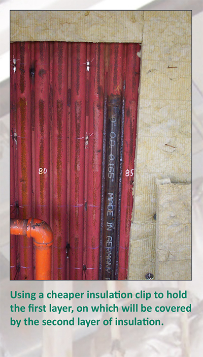 Figure 10
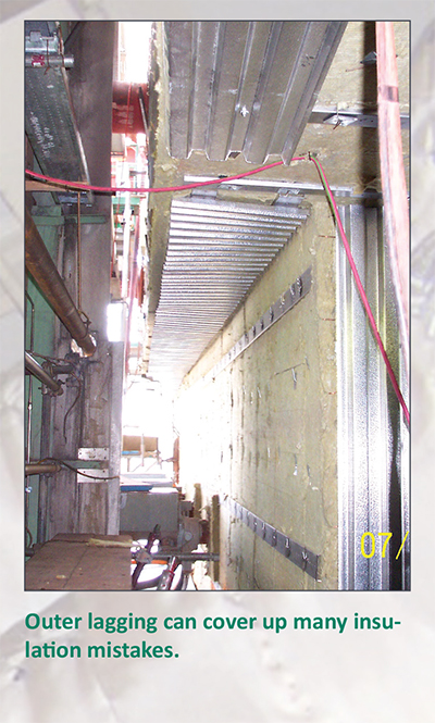 Figure 11
 Figure 12
 Figure 13
 Figure 14
 Figure 15
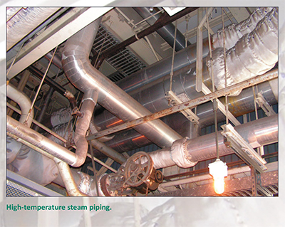 Figure 16