Below Ambient and Cryogenic Thermal Testing
Introduction: Measurement of Heat Flow
Thermal insulation systems operating in below-ambient temperature conditions are inherently susceptible to moisture intrusion and vapor drive toward the cold side. The subsequent effects may include condensation, icing, cracking, corrosion, and other problems. To test for thermal performance of a cold insulated pipeline under relevant conditions, we must be able to measure the heat (energy) flow. But, what is energy? No one really knows, but whatever it is, energy is the same at temperatures above ambient and below ambient. We do know that it always flows from the hotter side to the colder side.
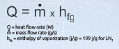
For below-ambient cases, the heat flow rate can be measured directly by the technique of boil-off calorimetry. Although it is a misnomer (there is no such thing as a “calorie meter”), the boil-off fluid, such as liquid nitrogen (LN2), provides a direct measurement of the rate of heat flowing through an insulation test specimen. The energy-going is the heat flow rate (Q), or power, in units of joules per second (W). The boil-off fluid vaporizes at a rate according to the rate of heat flowing through the test specimen. The boil-off flow rate is therefore directly proportional to the heat flow rate by the enthalpy of vaporization (hfg) as shown in the following equation. This simple equation is the essence of cryogenic boil-off calorimetry.
Boil-Off Calorimetry for Below-Ambient Thermal Testing
Cryogenic boil-off calorimetry is a steady-state method using a static, fixed volume of boil-off fluid. The boil-off fluid can be thought of as the “energy meter” for direct measurement of heat flow. The most typical boil-off fluid is LN2, but other fluids such a Freon or water have been used. The LN2 is saturated at ambient pressure for stability. The steady-state thermal equilibrium provides a heat flow rate that is the same through all layers of a test specimen. This fundamental principle is a key advantage over electrical-based thermal test methods since complex, non-isotropic, non-homogeneous, or layered insulation systems can be tested as directly as uniform slabs of isotropic, homogeneous materials. How? Boil-off calorimetry measures the heat flow rate, not just temperature or voltage. The temperature range for current standard capabilities is from about 100°C (373 K) down to -196°C (77 K). A large temperature difference (∆T) is typical and is more representative of the real-world conditions. With a large ∆T to work with, thermal conductivities at different mean temperatures (Tm) can also be calculated. In this way, multiple test points can be obtained from a single test.
Configurations of boil-off calorimeter systems can be flat plate or cylindrical. A horizontal cylindrical design is used for pipe insulation. The thermal measurement method can be absolute or comparative depending on the test objectives. The new standard published by ASTM International, C1774—Standard Guide to Thermal Performance Testing of Cryogenic Insulation Systems, includes 3 different approaches (boil-off or electrical power) and 6 different apparatuses (4 boil-off). Section X1.2 states that the approaches, techniques, and methodologies can be adapted for use in the cryogenic thermal performance testing of pipelines: cryogen boil-off (static) or flow-through (dynamic). Another new and related standard of ASTM International is ASTM C740—Standard Guide for Evacuated Reflective Cryogenic Insulation. This standard includes thermal performance data for multilayer insulation (MLI) and other cryogenic insulation systems, foams, aerogels, and bulk-fill materials operating between ambient and cryogenic temperatures. Key definitions from ASTM C1774 and ASTM C740 are listed as follows:
- Effective thermal conductivity (ke)—The thermal conductivity through the total thickness of the insulation test specimen between the reported boundary temperatures and in a specified environment (mW/m-K). The insulation test specimen may be one material, homogeneous or non-homogeneous, or a combination of materials.
- System thermal conductivity (ks)—The thermal conductivity through the total thickness of the insulation test specimen and all ancillary elements such as packaging, supports, getter packages, enclosures, etc. (mW/m-K).
- Heat flow rate (Q)—Quantity of heat energy transferred to a system in a unit of time (W).
- Heat flux (q)—Heat flow rate, under steady-state conditions, through a unit area, in a direction perpendicular to the plane of the thermal insulation system (W/m2).
Below-Ambient Testing
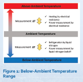
By placing a first insulation layer on the cold side, the cryogenic boil-off method can be used for any below-ambient temperature application.
Establish a steady warm boundary temperature (WBT) on an outer surface and establish a steady cold boundary temperature (CBT) on an inner surface. By placing a first insulation layer on the inner cold boundary, the cryogenic boil-off method is used for a wide range of below-ambient temperature applications. Three main phases: (1) Cooldown/fill; (2) Cold soak; and (3) Test (steady-state boil-off). After thermalization, the heat flow rate (Q) through the insulation is constant and the same through all layers of the insulation system. Heat flow rate: Q = boil-off flow x heat of vaporization.
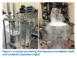
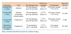
Flat plate boil-off instruments are listed in Table 1. The Cryostat-500 insulation test instrument, per ASTM C1774, Annex A3, provides the following capability: testing 204-mm diameter, 25-mm thick specimens under representative-use conditions; direct energy rate measurement by LN2 boil-off calorimetry; and reliable thermal conductivity data for non-homogenous, non-isotropic thermal insulation systems. A Cryostat-500 instrument is shown in operation in Figure 2.
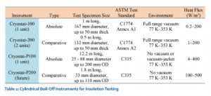
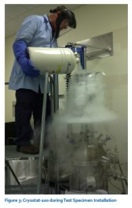
Cylindrical boil-off instruments are listed in Table 2. The Cryostat-100 insulation test instrument, per ASTM C1774, Annex A1, provides the following capability: testing 1-meter long, 218-mm diameter specimens under representative-use conditions; direct energy rate measurement by LN2 boil-off calorimetry; and reliable thermal conductivity data for non-homogenous, non-isotropic thermal insulation systems. A Cryostat-100 instrument is shown in operation in Figure 3.
Below-Ambient Insulated Pipe Testing
Of particular interest is the application of boil-off calorimetry to the testing of pipe insulation for cold applications. The potential revision of ASTM C335 to include a below-ambient method based on cryogenic boil-off is under review of ASTM International’s Committee C16 on Thermal Insulation. An apparatus and method for thermal performance testing of cryogenic piping systems has been established by the Cryogenics Test Laboratory at the NASA Kennedy Space Center. This apparatus, called Cryostat-P100, provides heat leak data for pipelines under “real world” conditions and a standardized thermal test for low-temperature piping systems. A comparative type, bench-top cold pipe tester, Cryostat-P200, is currently under development. Current research work of the Cryogenics Test Laboratory includes testing of below-ambient thermal insulation materials/systems for energy-efficient transfer lines and piping systems.
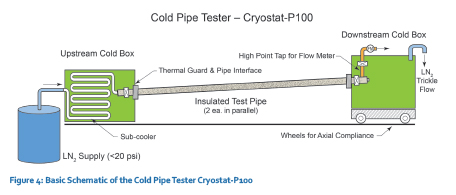
The cold-pipe tester, Cryostat-P100, is a liquid nitrogen boil-off test apparatus, thermally guarded for absolute heat leak rate measurements. This apparatus has a provision for 2 insulated test pipes of the following dimensions: 12-m long (40 feet) and up to 3-inch diameter pipe size (NPS). The insulated test pipes are tested in parallel. The piping can be continuous or segmented and rigid or flexible. Components such as valves, expansion joints, ports, and so forth can also be incorporated, if desired, as part of the test pipe configuration.
The system provides a 3° slope to provide a high point tap for the boil-off flow rate. An optional externally-applied heater wrap provides control of warm boundary temperature control. The anchors of the system are the upstream and downstream cold boxes as depicted in Figure 4. The cold boxes are filled with LN2 supplied from a normal low-pressure supply tank. The downstream cold box is filled from the upstream cold box through a vacuum-jacketed pipeline located in the middle between the 2 cold boxes. The test pipes are supplied with ambient pressure saturated LN2 from a heat exchanger coil routed through upstream cold box. Temperature sensors (Type E thermocouples) are usually installed in the following locations: length-wise (top, side, and bottom); through thickness of insulation; and terminations.
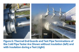
The thermal end guards and test pipe terminations are shown in Figure 6. These terminations are adaptable to a variety of different end connections. The terminations are thermally guarded by the liquid nitrogen bath of the cold boxes to which they are connected. The connections provide built-in compliance for thermal contraction and ease of installation of the test pipes. The middle line is typically used for downstream cold box supply but can be configured for a third test pipe.
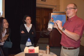
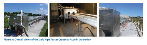
The basic phases of operation are listed as follows: cooldown and fill, cold soak, and boil-off test. Overall views of the cold pipe tester Cryostat-P100 in operation are shown in Figure 5. The test pipes are then refilled and allowed to thermally stabilize for a short period of time after which another test run is performed. This process is repeated as many times as desired for a complete test series. The system is then drained, purged, and allowed to warm to ambient temperature.
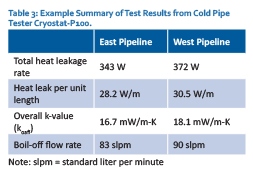
As an example of the test results, Table 3 presents a summary from a test of a 1.5-inch thick clamshell type insulation system on two 3-inch Nominal Pipe Size pipelines. The 2 pipes were insulated and installed in the same way and tested in parallel. The boundary temperatures were approximately 293 K (warm side) and 78 K (cold side). The cold soak phase was a minimum of 8 hours followed by multiple test runs within a few hours. The average data for 3 runs is given in the table.
Future Plans
Thermal insulation systems operating in below-ambient temperature conditions are inherently susceptible to moisture intrusion and vapor drive toward the cold side. The subsequent effects may include condensation, icing, cracking, corrosion, and other problems. Methods and apparatus for real-world thermal performance testing of below-ambient systems have been developed based on cryogenic boil-off calorimetry. Continuing to develop partnerships among industry, academia, and laboratories are essential for success in producing the needed technical consensus standards for below-ambient testing of pipe insulation.
The newly published standard guide to cryogenic testing, ASTM C1774, provides a foundation for the development of a new standard method that is specific to cold pipe testing. Another option is to revise the well-established pipe insulation test method, ASTM C335, to include 2 parts, one for the current above-ambient test and one for the below-ambient test. A key aspect of the work reported here as well as the ASTM C1774 is that provision is made for both insulation materials and insulation systems. The system aspect for insulated cold pipe lines operating in the ambient environment cannot be overstated. The cold pipe tester Cryostat-P100 provides a way of measuring the effective thermal conductivity of insulation materials under relevant conditions as well as determining the real-world thermal performance of insulation systems including installation and environmental factors.
Consistent techniques for establishing different prescribed cold boundary temperatures from about -100°C up to 0°C must be verified through testing across the full range of temperatures of interest to industry applications. Advance planning for future round-robin testing of select insulation materials is recommended. Also under development is a comparative type, bench-top cold pipe tester, Cryostat-P200, for 1.5-meter long and 25-mm diameter (nominal) pipe insulation systems.
Reference Publications
- Fesmire, J.E., “Standardization in cryogenic insulation systems testing and performance data,” Physics Procedia 67, 1089 – 1097 (2015).
- ASTM C1774—Standard Guide for Thermal Performance Testing of Cryogenic Insulation Systems. ASTM International, West Conshohocken, PA, USA (2013).
- ASTM C740—Standard Guide for Evacuated Reflective Cryogenic Insulation. ASTM International, West Conshohocken, PA, USA (2013).
- ASTM C335—Standard Test Method for Steady-State Heat Transfer Properties of Pipe Insulation. ASTM International, West Conshohocken, PA, USA.
- Fesmire, J.E., Johnson, W.L., Meneghelli, B., and Coffman, B.E., “Cylindrical boil-off calorimeters for testing of thermal insulations,” IOP Conf. Series: Materials Science and Engineering 101 (2015).
- Fesmire, J.E., Johnson, W.L., Swanger, A., Kelly, A., and Meneghelli, B., “Flat plate boil-off calorimeters for testing of thermal insulation systems,” IOP Conf. Series: Materials Science and Engineering 101 (2015).
- Demko J A, Fesmire J E, Johnson W L and Swanger A M, “Cryogenic insulation standard data and methodologies,” Adv. Cryog. Eng., AIP Conf. Proc. 1573, pp 463–70 (2014).
- US Patent 6,715,914 “Apparatus and Method for Thermal Performance Testing of Pipelines and Piping Systems.”
- Fesmire, J.E., Augustynowicz, S.D., and Nagy, Z.F., “Thermal Performance Testing of Cryogenic Piping Systems,” 21st International Congress of Refrigeration, Washington, DC, International Institute of Refrigeration, Paris (2004).
Copyright Statement
This article was published in the July 2016 issue of Insulation Outlook magazine. Copyright © 2016 National Insulation Association. All rights reserved. The contents of this website and Insulation Outlook magazine may not be reproduced in any means, in whole or in part, without the prior written permission of the publisher and NIA. Any unauthorized duplication is strictly prohibited and would violate NIA’s copyright and may violate other copyright agreements that NIA has with authors and partners. Contact publisher@insulation.org to reprint or reproduce this content.