Factors Influencing the Likelihood of Surface Condensation on Mechanical Systems Insulation, Part 2
As discussed in Part One of this article, correctly insulating pipe and mechanical equipment is critical because it prevents condensation on the outer surface of insulation systems. Part One of this series, which ran in the July 2012 issue of Insulation Outlook, discussed the influence of the design and climatic factors that affect condensation control. Part Two focuses more on the practical application of this knowledge, with a discussion of how to select the optimal design conditions and system components to reduce condensation in mechanical insulation systems. In addition, this article provides trouble-shooting advice to help you avoid some common mistakes related to achieving condensation control.
Selecting Design Conditions and System Components Design Ambient Temperature
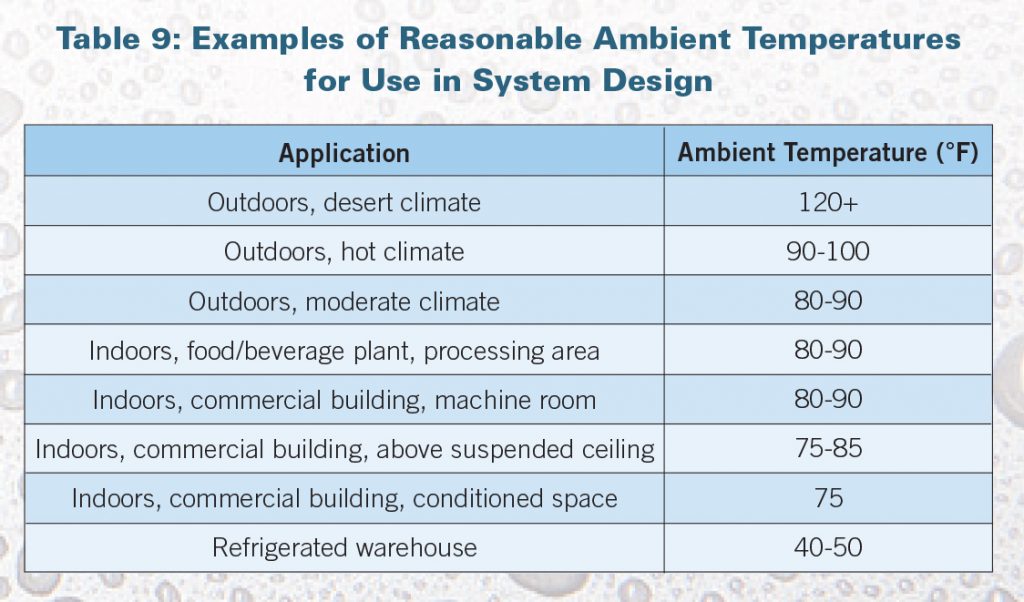
Recall from Part One of this article that ambient temperature has only a small effect on condensation control and the insulation thickness needed to prevent condensation. As a result, the accurate selection of an ambient temperature is simply not important. The most common, and a perfectly acceptable, approach is to select a reasonably harsh temperature for the situation. Table 9 shows some examples of reasonable ambient temperatures to use when designing insulation systems for several different applications.
Of course, if energy efficiency is rated more highly, (a separate design criterion than condensation control) the selection of ambient temperature is of critical importance.
Design Wind Speed
For indoor applications, it is usually best to select 0 mph (no wind) unless it is certain that forced ventilation will always be present to provide a wind speed above zero.
For outdoor applications, there are two approaches that can be used. A reference source for climatic information can be used, such as the ASHRAE Handbook of Fundamentals; an online database (e.g., weatherbase.com); or a computer program with weather data (e.g., WYEC2 and TMY2). The problem with this approach is that it is not clear which type of wind speed value should be used. Should it be a yearly average, the highest speed recorded, some high percentile value (e.g., 99th), or something else? As an alternative, the industry standard 7 mph value can be used unless the system is known to be in a high or low wind location. Examples of locations where a higher wind speed may be appropriate include on or near the ocean shore, under bridges, and in mountain passes. An example of a location where a lower wind speed may be appropriate is a rooftop location, where the pipe is blocked from the prevailing winds by some solid structure. While it is certainly inaccurate to use a single 7 mph value as a rule of thumb for most locations, this approach does have the advantage of simplicity and is widely practiced.
Insulation Type and Thermal Conductivity
Among the many considerations that should influence the selection of the insulation material type, one key factor is the insulating ability (thermal conductivity) of the material. When it is reasonable and appropriate, select an insulation material type that has the better (lower) thermal conductivity. Once an insulation material type has been selected (or in situations where it has already been specified), obtain thermal conductivity data for that insulation material from the most recent version of the appropriate ASTM material standard. Be cautious of relying on thermal conductivity claims by individual manufacturers. There are many ways to obtain thermal conductivity test values that are better than those published in the ASTM standards, and these “better” values may not be truly indicative of long-term material performance.
System Geometry—Pipe Size and Flat Surface Orientation
Since the pipe size and orientation of any flat surface will be established by the needs of the facility, these factors cannot b
e controlled by the insulation system designer. However, it is the insulation designer’s responsibility to understand the effect that the pipe size and flat surface orientation will have on the likelihood of condensation and determine the insulation thickness needed to prevent this condensation. The designer must determine the required insulation thickness for each pipe size and surface orientation independently.
Jacket Type—Emittance (Ɛ)
For most applications in North America, the jacket choices are straightforward. In outdoor locations, aluminum jacketing (Ɛ=0.1) is used for ultraviolet (UV) resistance and strength. For indoor locations, PVC jacketing (Ɛ=0.9) is used. However, there are exceptions to these general practices, when a different jacket type is dictated by conditions specific to the application. In an indoor environment where a great deal of physical abuse is likely, such as in a loading dock, aluminum jacketing (Ɛ=0.1) should be considered. It also might be prudent to use a greater thickness of aluminum jacketing to provide even more protection from physical abuse. In an indoor or outdoor environment where there will be either excessive exposure to corrosive chemicals or a need for an especially high resistance to fire, stainless steel jacketing (Ɛ=0.3) should be considered.
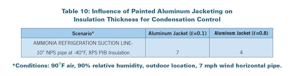
As mentioned in Part One, the use of painted metal, especially painted aluminum (Ɛ=0.8), can be helpful in reducing the likelihood of surface condensation or reducing the thickness of insulation necessary to prevent surface condensation. This benefit of painted metal jacketing arises because it has a higher emittance than bare metal. Consider, for example, Table 10, which shows the insulation thickness required to prevent surface condensation on an ammonia refrigeration line with standard aluminum and painted aluminum jacketing. The use of painted aluminum jacketing in this scenario yields an almost 50% reduction in insulation thickness. The use of painted aluminum jacketing also provides an increased resistance to exterior jacket corrosion and is particularly useful on rooftop refrigeration lines, operating at pipe temperatures in the -60°F to 20°F range.
While the use of jacketing with a higher emittance (e.g., painted metal) has a strong influence on the insulation thickness needed to control surface condensation, it should be noted that higher emittance jacketing has a minor influence on overall heat transfer. Therefore, the use of higher emittance jacketing will have minimal impact on energy efficiency.
Regardless of the type of metal jacketing used (aluminum, painted aluminum, stainless steel, or some other metal) it is critical that the metal jacketing has a 3-millimeter-thick Polysurlyn moisture barrier factory heat-laminated to the interior surface to help prevent galvanic and pitting/crevice corrosion on the interior surface of the jacketing.1
Relative Humidity
In mechanical insulation system design, selection of the proper relative humidity for controlling surface condensation is more complicated than the selection of the other
factors and has the largest influence on the necessary insulation thickness. The first step is to distinguish between indoor and outdoor locations.
Relative Humidity Indoors
For indoor locations, surface condensation on mechanical insulation systems can be a disaster, leading to demands that the contractor fix the system or even lawsuits. Surface condensation can drip on floors, causing slip hazards; drip onto manufactured goods, damaging them; drip onto food during processing or storage, contaminating it; and drip onto ceiling tiles, causing unsightly water stains. It can lead to mold growth on the surface of the vapor retarder, particularly when the outer surface of the vapor retarder is made of paper. It also can lead to mold growth inside the insulation system, especially when the insulation material offers little or no resistance to water absorption and water vapor permeability. Surface condensation can reduce the system’s insulating ability, which exacerbates the problem even further.
Indoors, surface condensation must be avoided 100% of the time. This is possible with a proper insulation system design, provided the indoor air is dehumidified and controlled at a relative humidity well below 100%.
Relative humidity in indoor locations can vary widely. Consider these examples:
- Food/beverage processing areas can have high relative humidity and be subject to wash-downs.
- Machine rooms of commercial buildings can have high relative humidity and can even be ventilated with outside air.
- Concealed areas of commercial buildings can have high relative humidity.
- Plenum areas of commercial buildings can have high relative humidity.
- Office areas and other occupied spaces of commercial buildings are usually low in relative humidity.
Insulated pipe in indoor locations should be designed to prevent surface condensation at a very high relative humidity compared to what is likely in that area. Designing for an ambient relative humidity of 85% or higher is completely reasonable since it is necessary to prevent surface condensation 100% of the time indoors. Designing for such a high ambient relative humidity usually has less impact on the required insulation thickness indoors because of the high emittance of the jacketing (usually 0.9), a typically smaller pipe size, and a usually more moderate pipe temperature—especially on chilled water lines in commercial buildings.
Relative Humidity Outdoors
To understand the philosophy of insulating to prevent surface condensation in outdoor locations, keep in mind that it is impossible to prevent surface condensation 100% of the time outdoors. Sooner or later, the relative humidity outdoors will reach 100%, which would require an impossible, infinite thickness of insulation to prevent surface condensation. Even if you design to a high relative humidity, such as 90 to 95%, outdoor conditions will eventually reach a relative humidity above this limit. This high humidity might be reached during, or immediately after, a rainstorm; on a cool morning when there is a heavy dew; or when there is fog. Any concern with the inevitability of surface condensation on outdoor cold pipe should be tempered by the realization that periodic surface condensation on outdoor pipe is perfectly acceptable. After all, the pipe surface gets wet from rain, dew, fog, and snow. It is not a significant problem if the frequency of surface wetness is increased slightly due to actual surface condensation.
The key for insulated pipe in outdoor locations is to design the system to prevent surface condensation a reasonably high percentage of the time, but how should this be done? Here are several approaches to consider.
1) 2009 ASHRAE Handbook of Fundamentals, Chapter 14
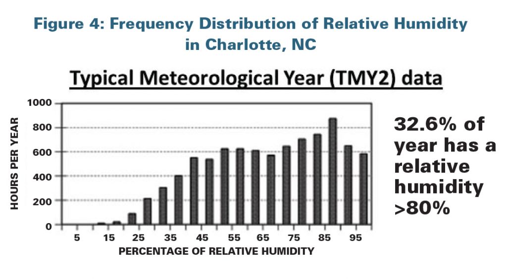
This is the trickiest approach (in this author’s opinion). The American Society of Heating, Refrigerating, and Air-Conditioning Engineers Handbook of Fundamentals, Chapter 14 contains climatic information on extreme conditions for numerous global locations. The tables in this chapter include the 0.4th percentile dew point and mean coincident dry bulb (MCDB) temperature. From this information and a psychrometric chart or program, the percent of relative humidity can be determined. However, field experience suggests that the conditions arising from this approach may not be harsh enough. As an example, consider the information in this chapter for Charlotte, NC. The 0.4th percentile dew point is 74°F with a MCDB temperature of 80.8°F. This yields a relative humidity of 80%. However, consider Figure 4, which shows the frequency distribution of outdoor relative humidity based on the typical meteorological year data for Charlotte.2 As the figure shows, the relative humidity is above 80% for a significant portion of the year (32.6%). Often, this approach seems to yield design conditions that are not strict enough and would allow surface condensation too frequently.
2) 2009 ASHRAE Handbook of Fundamentals, Chapter 23
This chapter recommends the use of 90% relative humidity for all outdoor applications and indoor applications vented to outdoor conditions. This is coupled with the 0.4th percentile dew point and with the use of a psychrometric chart, to determine the dry-bulb temperature. Using the Charlotte, NC example again, the 0.4th percentile dew point is 74°F. Coupling this with 90% relative humidity yields a dry-bulb temperature of 77°F, so the design conditions recommended according this approach would be 77°F and 90% relative humidity. The approach, however, ignores the fact that the 0.4th percentile dew point has an MCDB temperature already associated with it, as was discussed in the first approach.
The approach of always using 90% relative humidity would probably yield acceptable results in commercial building chilled water applications, where the pipe temperature is seldom lower than 40°F. For colder temperature applications, and especially those at cryogenic temperatures like liquid oxygen ( 297°F), liquid nitrogen (-320°F), liquid natural gas (LNG) ( 265°F), and even extremely cold ammonia refrigeration lines at -40 to -60°F, the use of 90% relative humidity yields a requirement for an insulation thickness to prevent surface condensation that is often considered impractical. Instead, the system designer would design to a lower relative humidity, accept the consequence of more frequent surface condensation, and design other aspects of the insulation system to prevent damage from the surface condensation.
3) Author-Recommended Approach to Selecting Outdoor Design Relative Humidity
Unless there are detailed, specific reasons to use a higher or lower relative humidity, use a value in the range of 80 to 90%. Within this recommended range, select a specific value based on knowledge of the climate at the job location and the pipe temperature. At warmer pipe temperatures, including chilled water in the 35 to 45°F range, it is reasonable to use 90% relative humidity. At colder pipe temperatures, use the lower design relative humidity values in the range (80 to 85%) to determine the required insulation thickness. Once you have selected the thickness, evaluate it to see if it is impractical. If it is too thick, take steps to reduce the required insulation thickness. This could mean using a higher emittance jacket, such as painted metal instead of bare metal, or it could mean designing to a lower relative humidity with commensurate changes to other aspects of the system design, such as vapor retarder permeance and quality, to prevent system damage from the more frequent surface condensation.
Common Mistakes, Tricks, and Tips
Common Mistakes in Mechanical System Design Related to Surface Condensation
- Owners, system designers, or others involved want the insulation system designed to prevent condensation at 100% relative humidity, commonly manifested in a request for an insulation thickness that will prevent condensation at 100% relative humidity. This cannot be done, as it would require an infinite thickness of insulation to accomplish. The proper approach is to design to between 80 and 90% relative humidity outdoors, depending on various factors described above, and to about 85% relative humidity indoors.
- Owners, system designers, or others involved want the insulation system designed to prevent condensation 100% of the time in an outdoor location or an indoor location that is not climate controlled. This, too, cannot be done. Sooner or later, the relative humidity will rise to above any design value and will occasionally reach 100% relative humidity. To accomplish this impossible design goal would require an infinite insulation thickness. The proper approach is to design the insulation system to allow surface condensation a small, but not inexistent, fraction of the time and to design other aspects of the system so that this infrequent, but inevitable, surface condensation does not damage the insulation system.
- An insulation system is designed for climate-controlled indoor conditions, but the system is started up before the building is enclosed and completed. The insulation system is operating in an environment with a higher relative humidity than the system was designed to handle. Surface condensation in this situation is common and has caused some high-profile system failures.
- Unrepaired damage to the insulation system occurs during construction—often by other trades. This type of damage almost always causes breaches in what is supposed to be a continuous vapor retarder. If the system is started up without repair to the damaged insulation system, water vapor quickly enters the insulation system and condenses. This is the beginning of a classic vicious cycle. The condensed water leads to a decreased insulating ability of the insulation (higher/worse k-Factor), which leads to more condensation and an ever-worsening k-Factor. Water intrusion into the insulation system also can cause pipe and jacket corrosion, mold growth, ice formation, and a loss of process control.
- The system is designed for 50% relative humidity in an indoor location. This level of relative humidity may make sense in the occupied portion of an office building, if the air conditioning/dehumidification system can guarantee this value is never exceeded. However, there are other parts of a commercial building that may have higher relative humidity, including machine rooms, kitchens, locker/shower rooms, and even concealed spaces like pipe chases. It is critical that the humidity is not assumed to be always less than 50% in these other portions of the building. In light industrial facilities, such as food and beverage manufacturing, high humidity processing areas can readily exist despite the air conditioning in the building or in portions of the building. The same pipe may need different thicknesses of insulation or other changes to the insulation system, depending on where in the building it is located.
- An emittance of 0.4 is used for aluminum jacketing. This is a common error based on some older specifications and handbooks that list this value as the emittance of aluminum jacketing. Using this incorrectly high value will result in inadequate insulation thickness to prevent surface condensation at the specified conditions. An accurate value to use for standard oxidized in-service aluminum jacketing of all finishes (plain, stucco, and 3/16” corrugated) is 0.1. This emittance is also contained in the new ASTM standard on aluminum jacketing, C1729.
A Useful Trick in Mechanical System Design Related to Surface Condensation
- Use painted metal jacketing to significantly increase the emittance. Bare aluminum has an emittance of 0.1, while painted aluminum is 0.8. This is a large increase, since the scale of emittance only goes from 0 to 1. Making this change will raise the surface temperature significantly, which will either reduce the insulation thickness required to prevent surface condensation or prevent surface condensation to a higher percent relative humidity. This trick is most helpful in outdoor applications where metal is the preferred type of jacketing. While not widely practiced in cryogenic applications, this is a trick that engineers and other system designers should consider when designing insulation systems to prevent surface condensation on pipes and other mechanical equipment operating at cryogenic temperatures. Painted aluminum jacketing has the added advantage of being more corrosion resistant than standard (bare) aluminum jacketing.
Tips to Prevent Surface Condensation
- Contractors, facility owners, and insulation system designers should work with manufacturers who understand the complex design issues described in both parts of this article. Some insulation manufactures know as much or more about aspects of insulation system design as those charged with designing these systems. Contractors, facility owners, and insulation system designers should seek input from these knowledgeable manufacturers on selecting appropriate design conditions and on insulation system design. However, they also should educate themselves on these issues so that manufacturers’ recommendations can be properly assessed.
- When comparing insulation materials, comparing insulation thickness tables, or preparing new insulation thickness tables, it is critically important that the same conditions be used for all materials. Even a seemingly small change, like one manufacturer using an aluminum emittance of 0.4 while another uses the correct value of 0.1, can have a significant impact on the recommended/calculated insulation thickness.
- While this article focused on condensation control, remember that it is only one design criterion. There are many other possible design criteria including (but not limited to) code compliance, process control, energy efficiency, personnel protection, and fire protection.
- This article is just an overview of the impact of various factors on the likelihood of surface condensation. It is not intended to replace proper system design by an engineer experienced with mechanical insulation on cold surfaces. Insulation system design has many subtleties that are not addressed by the more simplistic review presented here.
Conclusions
Surface condensation on insulation systems for cold mechanical equipment (pipes, tanks, vessels, etc.) is a simple concept. Surface condensation will occur if the surface temperature of the insulation system is less than the dew point temperature of the surrounding air. The concept is made complicated because each of these two temperatures is dependent on the interrelationship of a myriad of factors, as shown in Figure 5.
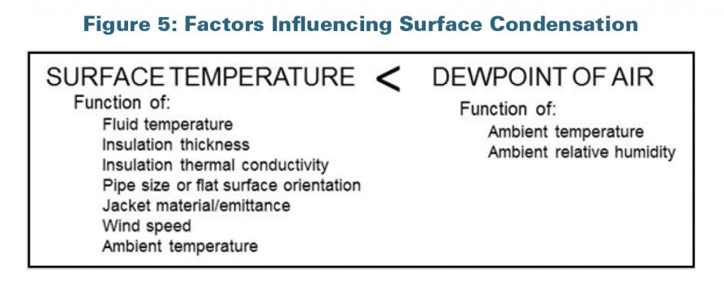
All of these factors must be fully and properly considered and selected to ensure optimum control of insulation system surface condensation—commonly called condensation control.
Of these factors, the selection of the proper relative humidity to use for system design is the most important and the most complicated to handle.
One last, but very important, point to emphasize is that for outdoor applications, surface condensation cannot be prevented 100% of the time.
REFERENCES:
- J. Young, “Preventing Corrosion on the Interior Surface of Metal Jacketing,” Insulation Outlook, November 2011.
- ASHRAE 2009 Handbook of Fundamentals, Chapter 23, p. 3.
NOTE: This article is based on Jim Young’s presentation at the NIA 57th Annual Convention. He also will present this information at the Refrigerating Engineers and Technicians Association (RETA) 2012 National Conference & Heavy Equipment Show November 6-9, 2012. Information on the show can be found at www.reta.com/convention/2012/index.html. © Copyright 2011 ITW Insulation Systems.