Mastics, Coatings, and Sealants: The Little Things Count
Mechanical insulation systems are often a complex combination of materials designed to work in synergy with each other and provide specific benefits. Individual materials may be used to provide a number of features, and they often rely on the other products used to achieve the performance required over the life of the application. Some elements that must be considered are the pipe or vessel material, insulation type and thickness, installation accessories, and protective cladding options. All these products must be chosen carefully to get the operational benefits intended from the entire mechanical system. However, even when great care is used to select the optimum offering for each of these materials, they are often not enough to provide the long-term system performance an owner, engineer, or contractor requires of an application. Mastics, coatings, and sealants sometimes can be overlooked as just a small piece of the insulation system, but they are a crucial part of the system’s overall design and longevity. In many cases, the mastic, coating, and/or sealants may be the system’s last line of defense, protecting it from any number of sources of potential damage.
Purpose and Importance of Mastics, Coatings, and Sealants
Mastics, coatings, and sealants are used for many reasons in a mechanical insulation system. Some products provide multiple functions, while others are much more specific in their properties and function. In insulation applications, mastic typically refers to a high-viscosity coating applied by trowel or brush, or gloved on; while coatings are lower viscosity and applied by brush or spray. For the purposes of this article, the terms “mastics” and “coatings” will be referred to as mastics for simplicity. A variety of parameters should be considered when selecting these products for optimal system performance. For a detailed list of mastic properties and test methods, refer to ASTM C647–19, Standard Guide to Properties and Tests of Mastics and Coating Finishes for Thermal Insulation.
In many cases, mastics will provide physical protection to the insulation material itself. Their relatively thick application and inherent strength and flexibility provide a toughness that the insulation surface cannot achieve on its own. Most mastic manufacturers also recommend that reinforcing mesh be installed in conjunction with the mastic to reinforce the film and provide superior toughness and higher resistance to cracking during any expansion and contraction of the insulation system that may occur. Another characteristic of this type of product is its ability to protect insulation from degradation resulting from sunlight and ultraviolet (UV) radiation. Many insulation materials will not hold up or retain their properties when exposed to extended periods of sunlight, so a protective mastic designed for outdoor exposure can prevent damage from the elements and UV radiation, and help maintain overall system performance.
Arguably, the most important property of mastics and sealants in any insulation design is their ability to keep water (both liquid and vapor) out of the system. Water is always present and trying to enter the insulation system, coming from sources such as an adjacent operations process, rain exposure, or simply latent humidity in the surrounding air. In any case, water can cause several issues if allowed to get into an insulation system. Wet insulation will lose some of its thermal insulating value, resulting in a less efficient system, costing the owner more money to operate or affecting temperature regulation and system design. Water also can cause physical damage to the insulation as it expands and contracts on systems that fluctuate between temperature extremes. Most importantly, water can lead to corrosion under insulation (CUI) if the insulation system is allowed to remain wet and is operating within temperature ranges where CUI is most likely to occur. All these situations can lead to higher operating costs, increased maintenance, and potential harm to the system itself.
Water Vapor Transmission and Permeance
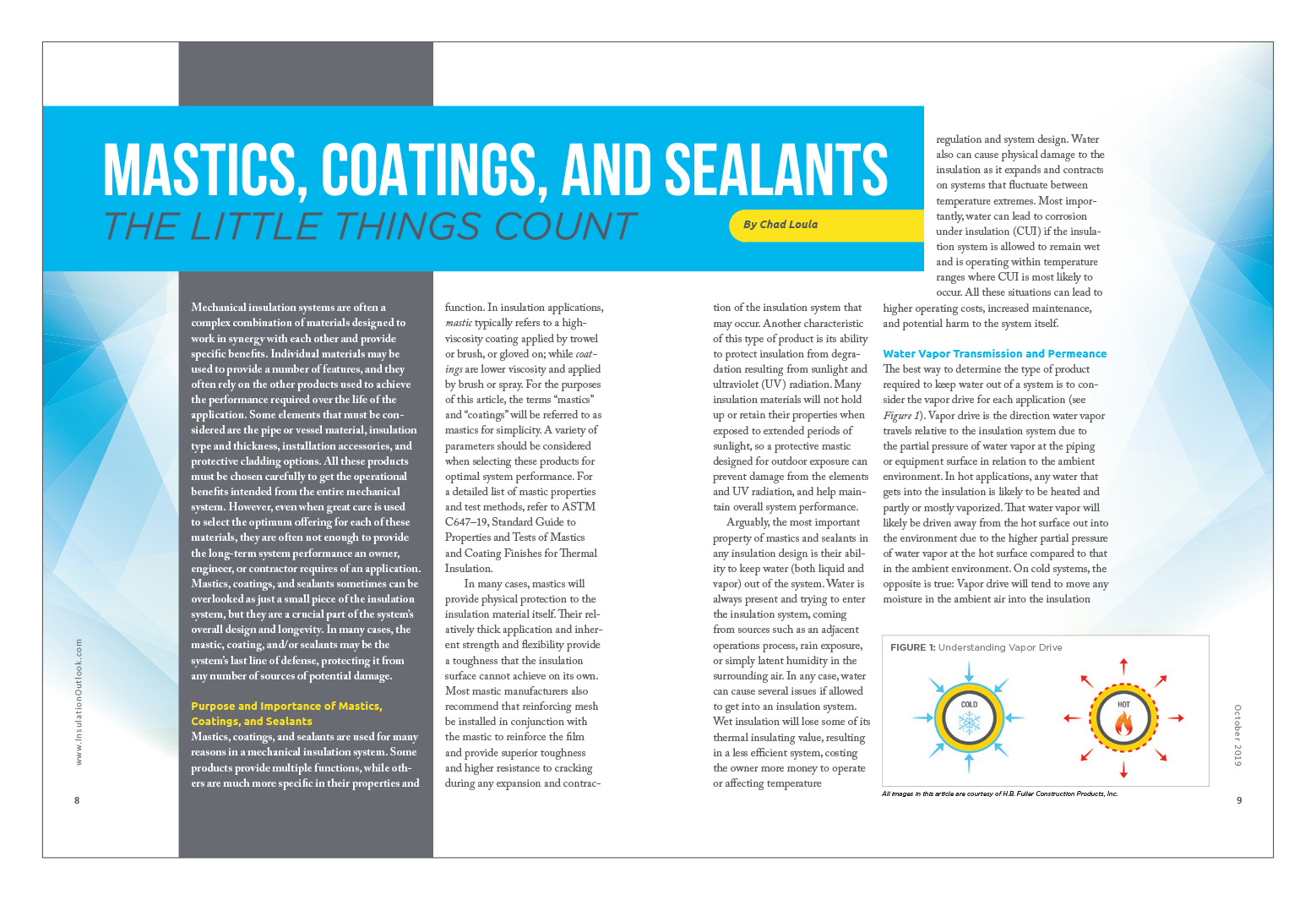
The best way to determine the type of product required to keep water out of a system is to consider the vapor drive for each application (see Figure 1). Vapor drive is the direction water vapor travels relative to the insulation system due to the partial pressure of water vapor at the piping or equipment surface in relation to the ambient environment. In hot applications, any water that gets into the insulation is likely to be heated and partly or mostly vaporized. That water vapor will likely be driven away from the hot surface out into the environment due to the higher partial pressure of water vapor at the hot surface compared to that in the ambient environment. On cold systems, the opposite is true: Vapor drive will tend to move any moisture in the ambient air into the insulation system and toward the cold pipe or vessel surface, where it likely will condense or freeze. By considering the vapor drive, you can determine which type of products will be best suited for the operating conditions of the application.

In order to understand how vapor drive relates to a product and its use on a system, you must also understand the term permeance. Permeance is a measure of the amount of water vapor that can pass through a given film of known thickness and area while under pressure over time—more simply, the water vapor transmission rate (WVTR) through a specified film at a specific water vapor pressure differential. The water vapor pressure differential is determined by the temperature and humidity on each side of the film. Permeance is most often expressed in the unit perms (grain/ft2•hr•in Hg) or metric perms (g/m2•24hr•mm Hg), but it also may be found using other combinations of units representing the mass per area, time, and vapor pressure differential. The lower the permeance value, the better it resists water from passing through
the film.
Two of the most common ways to measure permeance are ASTM E96–16, Standard Test Methods for Water Vapor Transmission of Materials, and ASTM F1249–13, Standard Test Method for Water Vapor Transmission Rate Through Plastic Film and Sheeting Using a Modulated Infrared Sensor. Manufacturers of vapor retarders often report results using one or both test methods. It is critical to make sure the data lists the dry film thickness at which the material was tested and the temperature and humidity at which the test was carried out. Without knowing these variables, it is impossible to compare the permeance values of 2 different products or ensure compliance with a given specification.
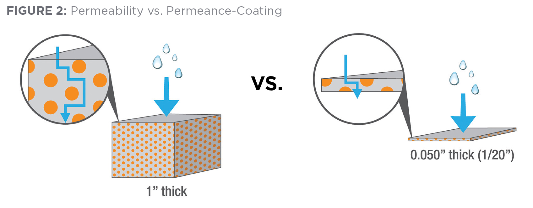
In the insulation industry, there is often confusion between the properties permeance and permeability. Permeability is the measure of a material’s permeance through a unit material thickness and is expressed as perm-inch—in other words, the permeance through 1-inch thick material. For insulation materials, permeability is a standard property, and its expression makes sense as insulation is used in thicknesses of an inch or more. However, in the case of dried mastics, vapor retarders, or jacketing membranes, a 1-inch thick material is not reasonable, and permeability should not be reported because it does not accurately reflect the performance of the material and it implies values much lower than can be achieved by the thin film. In rare cases, a coating, vapor retarder, or other membrane manufacturer may list permeability instead of permeance for its coating products, resulting in numerical permeability values ranging from 1/20th to 1/50th of the true permeance in perms. When considering selection of vapor retarders for insulation system, this must be considered (see Figure 2).
Weather Barrier (Breather) and Vapor Retarder Mastics
All mastics are designed to prevent intrusion of liquid water; but for water vapor permeance, the performance requirements for the mastic types will be different. Breather mastics, often referred to as “weather barrier mastics” when used over outdoor insulation surfaces, will allow higher levels of water vapor to pass through their films and will have typical permeance values greater than 1 perm. On hot applications, where the vapor drive is away from the hot surface, it is important to choose a breather mastic so any moisture that gets into the insulation system can escape as water vapor. Failure to allow for this escape can lead to blistering of the mastic or other damage to the insulation.
A vapor retarder mastic, on the other hand, is a product that resists or considerably slows the rate of water vapor transmission through a film over time and has a low permeance value. On cold systems, where the vapor drive is from the ambient air toward the pipe or equipment, these products are crucial to keeping not only liquid water but also water vapor out of the system. A vapor retarder system must be used over the entire outer insulation surface.
The correct vapor retarder mastic is an essential component of any cold insulation system design. The complete system should be considered to select the best product, depending on the operating temperature, insulationtype being used, exposure to elements or chemicals, and other vapor retarder films or membranes that may or may not be used in
the system.
ASTM C755–19, Standard Practice for Selection of Water Vapor Retarders for Thermal Insulation, provides guidance and considerations for the selection of vapor retarder systems, depending on system design requirements. In Table 2 of the standard, maximum permeance requirements for vapor retarders are provided based on insulation type, insulation application, and operating temperatures of the system. For the most common commercial and industrial applications of mastics on thermal insulation for piping and vessels, the table specifies maximum permeance limits tested by ASTM E96–16, Procedure A (desiccant method), of 0.05 perms for systems operating between ambient and 33oF, and 0.02 perms for systems operating below 33oF. For HVAC duct systems, the required vapor retarder permeance values for systems operating between ambient and 40oF, and 39oF and below, are a maximum of 1.0 and 0.02 perms, respectively, for low permeability insulations; and maximum 0.03 and 0.02 perms, respectively, for insulations with permeability greater than 4.0 perm-inch. Section 7.2.2 of ASTM C755–19 specifically discusses the use of mastics as vapor retarders and provides guidance for the mastics when used as the sole cladding material or in conjunction with a separate very low permeance vapor retarder membrane. When used alone, the mastics and coatings must have permeance values in accordance with Table 2 of the standard, or as described in 7.2.2.4. When used with a very low permeance vapor retarder membrane, where the mastics are used only to seal cut ends, seams, punctures, or damage to the membrane, and represent no more than 10% of the surface area of the total vapor retarder system, the permeance value of the mastics may be up to 0.15 perms for systems operating from ambient to 33oF, or 0.05 perms for systems operating below 33oF, such that the total system performance is in accordance with Table 2.
Another commonly specified requirement of vapor retarder mastics is MIL-PRF-19565C, Performance Specification: Coating Compounds, Thermal Insulation, Fire- and Water-Resistant, Vapor-Barrier. This specification was developed by the U.S. military but is commonly cited in a variety of government and non-military design specifications for mastic-type vapor retarder materials. MIL‑PRF‑19565C is a performance specification consisting of many required vapor retarder mastic properties. Of major importance is the water vapor permeance requirement of 0.05 perms when tested to ASTM E96–16, Procedure A (desiccant method). In addition to the MIL-PRF-19565C specification, the U.S. Department of Defense also maintains a Qualified Product Database (QPD) of products that meet all the requirements of this specification. When choosing a product in compliance with MIL-PRF-19565C, it is important to select one listed on the QPD to ensure it has been tested to and meets the requirements as listed. Products that claim to meet the requirements of MIL-PRF-19565C but are not listed on the QPD have not been independently certified to comply with the requirements.
Other Properties
One important property to consider when selecting breather or vapor retarder mastics is the fire resistance of the dry film. Fire resistance is measured by ASTM E84–19, Standard Test Method for Surface Burning Characteristics of Building Materials, and is expressed in both a flame spread and smoke developed index. Many indoor applications require a flame spread of 25 or less, and a smoke developed of 50 or less; while outdoor applications often require a flame spread of 25 or less but have no smoke developed index requirement.
A variety of mastics are available in water- and solvent-based formulations, and each type has its benefits and disadvantages for certain applications. Water-based mastics are often preferable for indoor applications because they are non-flammable in the wet state and typically have lower odor during drying, due to a lower volatile organic content (VOC). Water-based mastics are usually compatible with all mechanical insulation types, as well. However, water-based mastics often have poorer (higher) water vapor permeance compared to solvent-based mastics. In some instances, such as cryogenic or industrial environments, a solvent-based mastic may be required where lower permeance, increased chemical resistance, or superior weather resistance are desired. In these instances, care must be taken when choosing the product to ensure it is compatible with the insulation to which it is being applied. Some insulation types, such as polystyrene foam insulation, will be attacked by the solvent makeup of some mastics, so care must be taken in the selection of the solvent-based mastic to prevent damage to the insulation material.
VOC content of coatings and sealants has become of increased importance in recent years due to air quality regulations in California, Canada, and several regions in the United States; in addition to the growth of green building standards, such as the U.S. Green Building Council’s LEED® program. This has resulted in greater awareness and emphasis being put into low-VOC products. As these programs have evolved over the years, many manufacturers have developed products to meet the newer program requirements. Whether it be for air quality purposes or exposure limits, maximum VOC content limits for mastics have been set to ensure low VOCs, while still meeting necessary performance characteristics of the mastics. Selection of zero VOC mastics instead of merely low VOC is not of any additional LEED point value, with respect to meeting the regulations and standards; and, depending on the product selected, it may compromise other performance factors. In many cases, VOCs in the product are necessary to improve overall performance of a mastic, and the new regulations and programs have taken this into account by allowing some level of VOCs in the products.
More recently, green building standards for commercial building construction, such as LEED v4, have begun requiring VOC-emission testing in addition to requirements for VOC content. VOC emissions are typically tested to the California Department of Public Health (CDPH) Specification 01350, which also sets emissions limits for products used within the building envelope, including coatings, adhesives, and sealants. Users must now confirm that manufacturers have conducted the proper emissions testing when selecting products for applications requiring these new programs as part of their specifications.
Sealants and Vapor Stops
In addition to the use of vapor retarder mastics on the exterior of cold insulation systems, products such as joint sealants and vapor stops are commonly used in conjunction with other vapor retarders to provide additional protection from the damaging effects of water entering the insulation system.
Joint sealants are high-solids, soft, paste-like materials applied in the joints of rigid insulations. The sealants themselves should have good vapor retarder properties to keep moisture from passing through the butt and longitudinal joints of the insulation sections. In colder applications where multiple layers of insulation are used, the innermost layer is typically allowed to float and is installed without the sealants. This allows the innermost layer to move with any expansion and contraction that might occur, while the remaining outer layer(s) will use sealant to help prevent moisture intrusion.
Vapor-stop sealants or vapor dams are used to prevent moisture migration into the insulation system at an insulation termination and from one section of insulation to an adjacent section. They are applied at critical points within the insulation system where water entry is more likely, such as at pipe supports, valve boxes, flanges, or other areas where access and maintenance may be required, as well as at specified intervals along the piping.
When fibrous insulation is used for the warmer end of cold systems, such as chilled water applications, a water-based vapor retarder mastic may be used as a vapor stop to seal off the exposed fibrous cut end. Care should be taken to apply the mastic on the pipe surface and up over the insulation to the outer surface, but not under the insulation at the bore, to avoid water being trapped within the insulation system (see Figure 3). Once applied, the mastic must be allowed to fully dry before adjacent insulation is installed. Failure to allow the mastic to dry completely will result in trapped water or solvent within the insulation system.
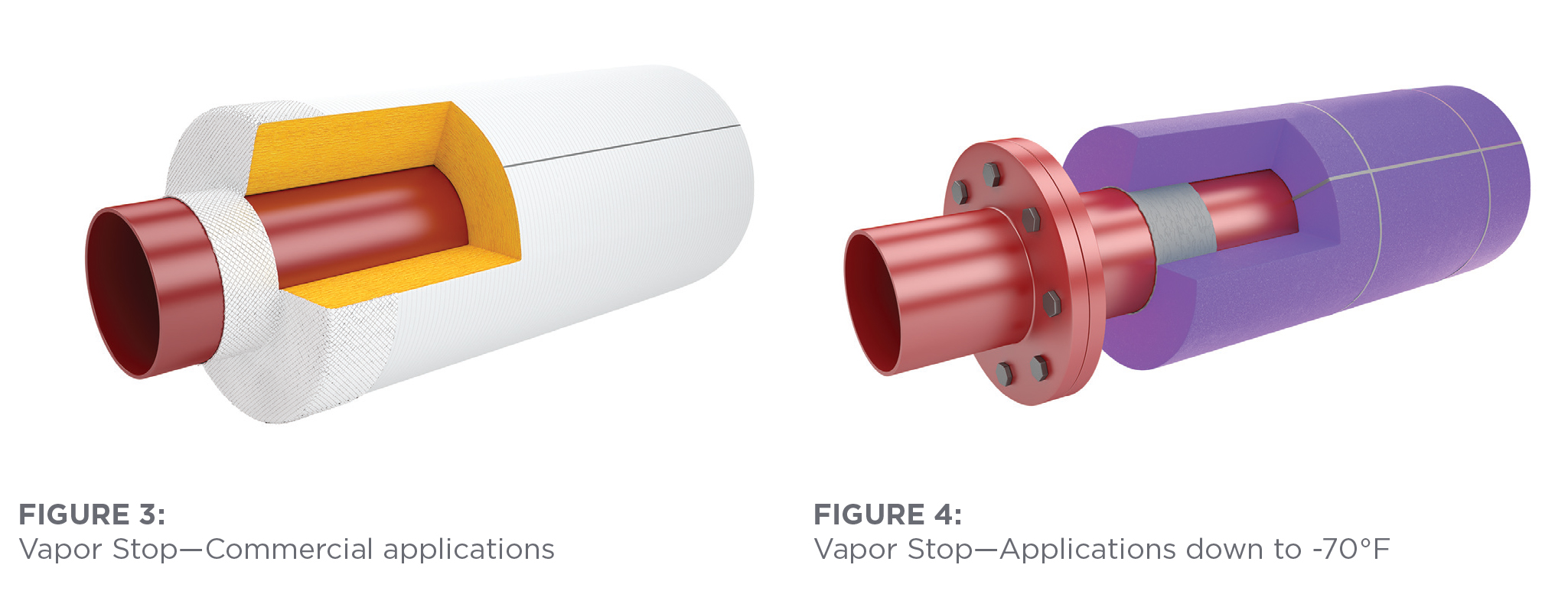
On refrigeration or cryogenic applications down to -70oF, with rigid insulation such as polystyrene foam, a high-solids, oil-based vapor retarder sealant, compatible with the polystyrene insulation, may be used as a vapor stop. In these applications, the sealant can be applied in a continuous film under the insulation layer between the bore of the insulation and the pipe, ensuring full contact (see Figure 4). The butt joints of the insulation also must be sealed from the pipe to the outer surface.
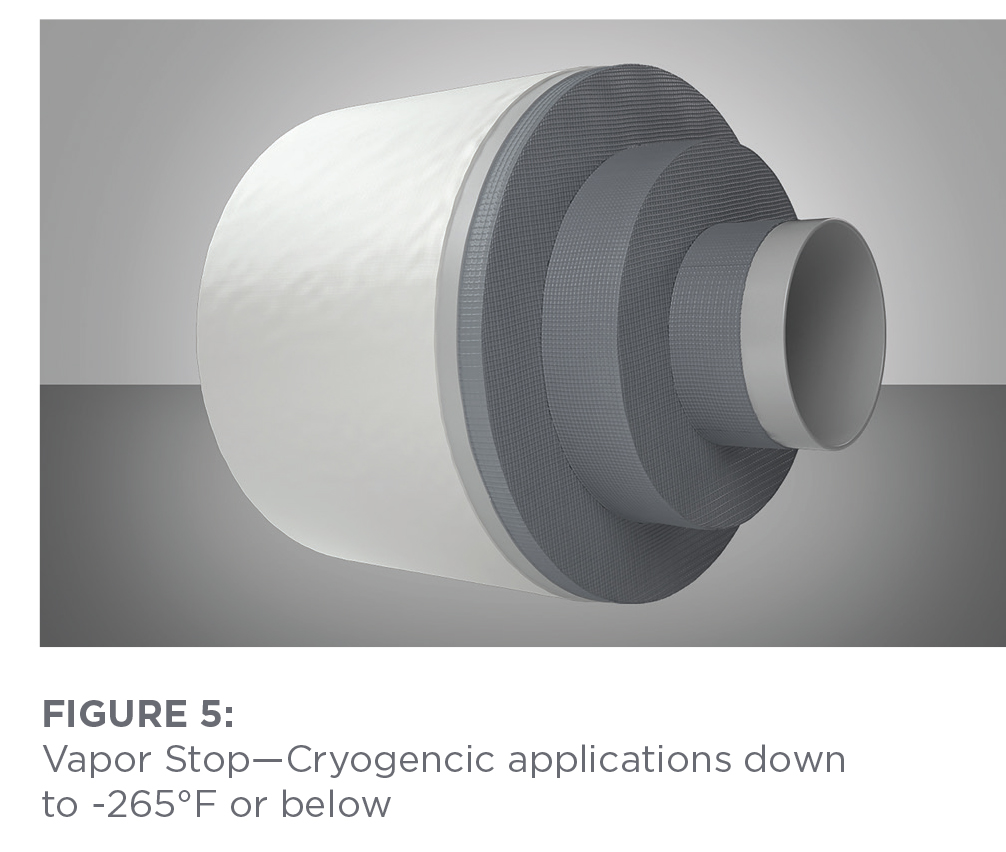
On cryogenic systems, the vapor stops are of particular importance. Vapor stop sealants or coatings for cryogenic systems are high-performance products with very low permeance, <0.01 perms, that must perform across a wide service temperature range down to -265°F or below. Selecting the right product is vital to an insulation system’s long-term performance. The products are applied directly to the pipe surface and onto each layer of insulation all the way to the outer insulation surface, where they tie into the exterior membrane-type vapor retarder. Because these products experience temperatures from the operating temperature through ambient conditions, it is critical to use reinforcing mesh when installing them to prevent cracking due to expansion and contraction. Additionally, a vapor stop always should be allowed to fully cure and dry before the final layers of insulation are installed over the vapor stop film. Failure to allow the product to fully dry will result in solvent entrapment in the insulation system and prevent further drying of the material once placed into service (see Figure 5).
Remember the Little Things While Keeping the Big Picture in Mind
Mechanical insulation systems are intricate designs consisting of many individual materials that must work together to achieve the intended result. On many systems, the mastics, coatings, and sealants used play a vital role in long-term system performance. Care always should be taken to ensure the products specified and used are compatible, designed for their intended use, and meet the specifications necessary to ensure a successful project. Taking the time and effort up front will ensure everyone involved completes an insulation system that will perform to its fullest potential for the life of the project.
Copyright Statement
This article was published in the October 2019 issue of Insulation Outlook magazine. Copyright © 2019 National Insulation Association. All rights reserved. The contents of this website and Insulation Outlook magazine may not be reproduced in any means, in whole or in part, without the prior written permission of the publisher and NIA. Any unauthorized duplication is strictly prohibited and would violate NIA’s copyright and may violate other copyright agreements that NIA has with authors and partners. Contact publisher@insulation.org to reprint or reproduce this content.