Thermal Insulation for Nuclear Power Plants and Nuclear Safety Issue GSI-191
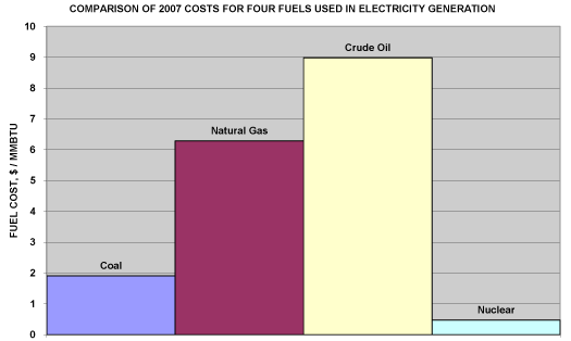
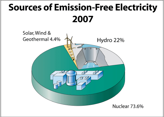
The 104 operating nuclear power plants in the United States and the 20 operating nuclear units in Canada produce about 20 percent and 15 percent, respectively, of the electrical power generated in North America. That share is expected to grow in the coming decades, with more than 30 nuclear power plants proposed by 17 consortia in the United States and an additional four plants proposed by one utility in Canada, all to be completed by the year 2030.
Thermal Insulation in Existing Nuclear Power Plants
It is beyond the scope of this article to explain how nuclear power plants work—and which parts need to be insulated—but basically a nuclear power plant boils water to create steam and rotate a turbine generator.
When discussing a nuclear power plant, it is necessary to distinguish between inside containment and outside containment. The containment is the cylindrical or box-like structure that houses the nuclear reactor.
Inside Containment
Work inside containment is difficult, and generally has stringent quality assurance (QA) requirements for materials and labor. This is true for electrical, structural, hydraulic, and even insulating materials and systems. Work inside a nuclear containment, including the supply and installation of insulation materials, is “on a different planet” compared with work in a fossil fuel power plant, chemical plant, or petroleum refinery.
The containment is a large space containing the nuclear steam supply system (NSSS), which can consist of the reactor, pipe, pumps, valves, and other miscellaneous components and equipment. The NSSS has a very large net positive heat load. Insulation on hot service pipe and equipment inside containment has one purpose: to control containment cooling loads. Containment cooling must remove that heat, whether linked directly to a body of water (e.g., a river, lake, bay, or ocean) or vapor compression cooling (i.e., air conditioning). If the NSSS heat sources inside containment release heat at a greater rate than the cooling equipment can remove it, the containment air temperature will rise above what the nuclear plant’s technical specifications allow.
The 104 operating U.S. nuclear units were constructed from the early 1960s through 1994. The NSSS piping and equipment in plants constructed through 1972 sometimes included asbestos-containing insulation materials. Other than that, the hot service pipes and equipment were mostly insulated with mineral wool, calcium silicate, fiberglass, microporous, refractory, glass fiber felt, and reflective metallic insulation (RMI). The cold service piping, carrying cold water to fan coil units, was insulated with fiberglass, cellular glass, or various plastic foams.
Some of these materials were installed as permanent insulation, not intended to be removed and reinstalled. However, after about the mid-1970s, new plants increasingly were insulated with pre-engineered, pre-fabricated systems designed for removability and reuse. The first of these were RMI cassettes (see Figures 1 and 2), soon followed by 100 percent removable/reusable fiberglass blankets with separate stainless steel jacketing (see Figures 3 and 4). In both systems, each insulation piece was uniquely tagged and its location shown on an assembly drawing. A new boiler water reactor (BWR) might have had some 6,000 insulation pieces and a pressurized water reactor (PWR) might have had 10,000 insulation pieces. The difference in insulation piece quantities is primarily due to the number of NSSS components and equipment associated with each type of reactor.
Quality Assurance
For both RMI and removable/reusable blanket systems, there were often requirements added by the nuclear plant architect/engineer (A/E) design firm to address thermal, seismic, and various other safety analyses to be included, all provided by the insulation supplier.
At some plants, QA called for insulation materials to be supplied as “Nuclear Safety Related,” which required production-lot specific control and documentation of all material components, including their source, design, fabrication, identification, packaging, and shipment. Sometimes even the insulation contractor’s installation labor was required to be “Nuclear Safety Related,” meaning the contractor had implemented a formal QA program, including hiring and training full-time quality control (QC) inspectors to verify that the insulation materials were correct and properly installed. Extensive documentation was required of what insulation materials, in what quantities, were installed where. Non-conforming materials had to be marked with “hold tags,” and resolved by formalized disposition procedures.
At some nuclear plants, however, there were no special QA requirements, and in some of those, there were no formal records of what type of insulation was installed where. There were always specifications, but not always documentation that the specifications were followed (and in some plants they were not).
After the plant’s commissioning, specifications were sometimes altered to allow different insulating materials to be added on a replacement basis, particularly for inside containment hot service pipe and equipment. For example, a number of plants developed high containment cooling load problems, as demonstrated by high containment air temperatures. At many of those plants, pre-engineered removable/reusable blankets replaced original RMI materials. Also, many of the PWR plants replaced their steam generators (i.e., huge heat exchangers) and many BWR plants replaced their primary piping systems, requiring new insulation that was either RMI or removable/reusable blankets with metal jacketing.
Outside Containment
Outside containment work at a nuclear plant is more similar to work at a fossil-fueled power plant.
Outside containment, calcium silicate was usually specified for pipe insulation because of both its high durability (due to its very high compressive strength and flexural strength) and its availability with chemical inhibitors, enabling its use on austenitic stainless steel pipes and equipment (to prevent stress corrosion cracking). Mineral wool and fiberglass were sometimes used, but I estimate that calcium silicate constituted approximately 90 percent of the outside containment pipe, component, and equipment insulation. The steam turbines were insulated with either calcium silicate block or removable/reusable blankets made with needled glass fiber felt insulation encased in woven glass fiber fabric.
Sump Blockage, Bulletin 96-03, and Generic Safety Issue (GSI) 191
BWR plants have a suppression pool, a large cylindrical volume of water contained around or underneath the containment to be used as a source of cooling in a large NSSS pipe break accident. In a large pipe break, a recirculation cooling system powered by large pumps starts up, drawing water from the suppression pool through strainers to the pumps, through heat exchangers, and back into the containment. Some of the water is injected onto the nuclear reactor to cool it down, and some is simply recirculated within the suppression pool to provide heat removal from the containment. The strainers on the pump intake pipes inside the suppression pool separate out debris that might damage the pump internals.
A PWR plant has a similar emergency cooling system, although there is no suppression pool. Rather, there is a sump pit in the lowest level of the containment with a screen over the top. In a large pipe break, large quantities of water are injected into the nuclear reactor as well as sprayed into the containment upper levels. Once the water level on the containment floor reaches several feet in depth, the emergency pumps turn on, drawing the accumulated water from the containment floor through the screens, into the pumps, through heat exchangers, and back into the containment. The screens separate out debris that might damage the emergency pump internals.
In both BWR and PWR plants, the emergency cooling system is designed to operate for at least 30 days following a pipe-break accident. Anything that could disrupt recirculation water flow could affect the cooling of the damaged NSSS.
In July 1992, an incident at a BWR in southern Sweden radically changed the rules for nuclear containment insulation. An NSSS steam relief valve accidentally opened, releasing a steam blast that blew off some pipe insulation sheet metal jacketing and destroyed a large quantity of mineral wool pipe insulation. The shredded mineral wool blew down into the suppression pool. The containment air temperature, which had suddenly increased due to the steam blast, triggered monitoring instrumentation that started the emergency pumps, which in turn circulated suppression pool water through coolers, and then pumped it back into the suppression pool. This incident has been well documented in nuclear power plant safety and regulation literature. For example, the United States Nuclear Regulatory Commission (NRC) Generic Letter 2004-02: Potential Impact of Debris Blockage on Emergency Recirculation During Design Basis Accidents at Pressurized-Water Reactors states:
On July 28, 1992, at Barsebäck Unit 2, a Swedish BWR, the spurious opening of a pilot-operated relief valve led to the plugging of two containment vessel spray system suction strainers with mineral wool and required operators to shut down the spray pumps and backflush the strainers.
At this plant, mineral wool debris became mixed into the suppression pool water by the steam blast agitation. When the emergency pumps started, the pressure drop across the emergency pump suppression pool strainers rapidly increased. In less than an hour, one pump started to cavitate and another was very close to cavitation. The plant operator shut off the pumps immediately so no damage was done.
Less than a year after the Swedish plant incident, there was another at the Perry Nuclear Plant near Cleveland, Ohio, also summarized in Generic Letter 2004-02:
In 1993, at Perry Unit 1, two events occurred during which ECCS strainers became plugged with debris. On January 16, ECCS strainers were plugged with suppression pool particulate matter, and on April 14, an ECCS strainer was plugged with glass fiber from ventilation filters that had fallen into the suppression pool. On both occasions, the affected ECCS strainers were deformed by excessive differential pressure created by the debris plugging.
These two incidents caught the attention of nuclear power plant operators around the world. In Sweden, the BWRs replaced their original small suction strainers with larger ones of considerably more surface area. The Swedish PWRs replaced their sump debris screens with larger strainer surface areas as well. They did this within a year of their plant incident.
Two years later there was a third incident, this time at one of the two Limerick Plants near Philadelphia, Pennsylvania (summary from Generic Letter 2004-02):
On September 11, 1995, at Limerick Unit 1, following a manual scram due to a stuck-open safety/relief valve, operators observed fluctuating flow and pump motor current on the A loop of suppression pool cooling. The licensee later attributed these indications to a thin mat of fiber and sludge which had accumulated on the suction strainer.
Both suction strainers in the “A” loop of suppression pool cooling were almost entirely covered with a thin “mat” of material, consisting mostly of fibers and sludge. The “B” loop suction strainers had a similar covering, but less of it. Analysis showed that the sludge was primarily iron oxides and the fibers were polymeric in nature. The source of the fibers was not identified, but the licensee determined that the fibers did not originate within the suppression pool and that no trace of either fiberglass or asbestos was in the fibers.
While all three were only nuclear incidents—not accidents—they did demonstrate that suppression pool emergency pump suction strainers were severely undersized. The Swedish plant incident demonstrated that fibrous pipe and equipment insulation could be shredded by a high-pressure steam or water blast. Both the Perry and Limerick incidents demonstrated that a small quantity of fibrous material, in combination with particulate, could collect on the safety strainers, resulting in pressure losses. All three of these incidents would have had greater safety implications in an actual NSSS pipe break loss-of-coolant accident (LOCA).
In the United States, the NRC in 1996 issued Bulletin 96-03, “Potential Plugging of Emergency Core Cooling Suction Strainers by Debris in Boiling-Water Reactors,” which incorporated lessons from the incidents at the Swedish plant, the Perry Plant, and the Limerick Plant. All U.S. BWR units were required to demonstrate by calculation that their plants’ emergency cooling systems could function after a large NSSS pipe break LOCA, taking into account all their containment insulation, all sources of particulate, and other sources of debris. As a consequence, by 1999, all 34 U.S. BWR units replaced their original suction strainers with larger surface area, high-capacity strainers. There were 4 to 10 new strainers added at each nuclear unit.
Most BWR plant owners who had containments with fibrous pipe insulation designed their new suction strainers to be large enough to operate even with lots of collected debris. However, the NRC also required all types of fibrous and granular insulation materials to be evaluated as possible sources of debris that could clog suction strainers. Fibrous and granular insulation had to be documented in terms of quantities, locations, and condition.
RMI, made with concentric layers of metal foils on the inside, was not found to be a source of debris that could clog strainers. Instead, the foils were merely blown into shreds that could collect on suction strainers but wouldn’t block water flow and wouldn’t filter out particles suspended in the water.
After the NRC’s issuance of Bulletin 96-03, BWR plant owners also instituted aggressive suppression pool cleaning programs, regularly vacuuming out the iron oxide “sludge” from pipe and suppression pool corrosion.
In the late 1990s, the NRC started a project known as “Generic Safety Issue-191: Technical Assessment: Parametric Evaluations for Pressurized Water Reactor Recirculation Sump Performance,” referred to as GSI-191. After several years of additional study, the NRC issued Revision 2 to existing Regulatory Guide 1.82: “Water Sources for Long-Term Recirculation Cooling Following a Loss-of-Coolant Accident.” This revised regulatory guide required the owners of PWRs to evaluate and correct any plant deficiencies, including installation of significantly larger surface area strainers, just as the BWRs had done. Today, all 69 U.S. PWR units, as well as all 20 operating heavy water nuclear plants in Canada, have replaced or are planning to replace their safety screens with high-capacity screens or strainers.
In the meantime, however, new questions arose about chemical reactions that could occur after a nuclear accident involving insulation debris, paint chips broken loose by the LOCA, and dissolved chemicals in the recirculation water designed to reduce nuclear radiation release following an accident. The chemical effects have made it difficult to show by testing and calculation that the new safety strainers or screens are large enough for the PWR plant in question. As of mid-June 2009, PWR plants are still conducting chemical effects tests, so the issue is not yet resolved.
Fibrous and granular insulation materials have been identified as sources of debris that could, in a LOCA, collect on emergency strainers and lead to high pressure losses. Regardless, the PWR plants with primarily fibrous or granular containment insulation are leaving most of it in place and designing their new screens or strainers to handle the debris. Because of this, U.S. plants with fibrous and granular insulation materials continue to operate within the guidelines of the NRC.
The U.S.-designed plants in Mexico, Spain, Belgium, Switzerland, Britain, South Korea, Japan, and other countries were also required by their nuclear regulators to replace safety strainers and screens with much larger surface area screens or strainers. Likewise, in countries with non-U.S.-designed plants, such as France, Germany, Japan, and Russia, the regulators also required that their plants address this issue.
Nuclear Plants Today
First, the good news: U.S. and Canadian nuclear plants are safer today than they were before adding the larger surface area strainers or screens. Many of these strainers/screens are approximately 100 times larger than the original ones—roughly 10,000 times safer for a given amount of debris. (See References for documentation supporting this section.)
Further, the nuclear plants have instituted programs to:
- control the quantity and types of paint used in containment to minimize paint chips in an accident
- improve containment cleanliness programs to remove sources of dirt and rust that could contribute to post-accident pressure losses across the safety strainers/screens
- identify their containment insulation types, quantities, and locations.
A post-accident, pipe break safety analysis for a nuclear plant, as far as thermal insulation debris sources goes, has four parts:
- debris generation
- debris transport
- chemical reaction
- head loss (pressure loss) across the strainer or screen.
The first step, debris generation, must be supported by sound testing and evaluation to make the rest of the analysis reasonable, accurate, and conservative. The questions of how much insulation is actually destroyed, how much debris is actually generated, and the form of that debris are extremely complicated. The questions could have been answered by tests that were well thought out and well executed, but, with a few exceptions, this was rarely done. As a consequence, the plant safety analyses to determine the size of the new suction strainers or screens and the role of insulation debris have been overly conservative due to assumptions of huge quantities of very fine insulation debris being generated by a large pipe break accident inside a nuclear plant containment building.
It was the responsibility of the nuclear industry to challenge the NRC’s assumptions by testing the insulation materials, the paint types used in containment, and other debris source materials, as well as the proposed new screens/strainers. The BWR Owners Group did conduct a series of high-pressure air jet tests in 1997, but these tests were dismissed by the NRC as being non-representative because they did not use a two-phase steam/water blast. One PWR utility conducted a test with stainless steel jacketing on calcium silicate. In the end, however, neither group conducted comprehensive debris-generation testing using high pressure steam/water.
Thermal Insulation in Future Nuclear Plants
This lack of debris-generation testing may have led to fibrous and granular insulation materials being seen as contributing debris to screen and strainer blockage. However, this issue is addressed by having adequate safety strainers or screens, which have already been installed in most of the 104 operating U.S. nuclear plants, typically without replacing existing fibrous and granular insulation materials.
RMI has been used in many nuclear power plants in the United States and overseas (although not in Canada). It has also been used on many replacement steam generators in PWR plants and recirculation piping projects in BWR plants. RMI cassettes are made of heavy gauge stainless steel sheet on the outside and light gauge stainless steel foils on the inside. The thermal performance depends primarily on maintaining the low emittance of the concentric foil layers. To a much lesser degree, the 1/4-inch to 1/2-inch wide air spaces between the foils provide some thermal performance. There is considerable opportunity for thermal bridging through the outer stainless steel shell from the hot surfaces to the outer jacket, as well as through gaps that can open up and at lap joints and butt joints. There is no effective way to make thermally effective expansion joints of the types frequently added with conventional mass insulation systems on high temperature applications, since fibrous materials generally are not allowed to be used with RMI systems.
When working with RMI, tremendous attention to detail must be paid during system design, fabrication, shipping, and installation. Steel has high thermal conductivity, and air spaces between concentric layers of foils can provide fairly high convective heat transfer. When the pipes expand upon heating, gaps open between adjacent sections of RMI, leading to additional heat transfer. RMI must be extremely well maintained, with damaged materials replaced as soon as possible, even more so than with conventional materials. Hence, if new nuclear plants use RMI in containment, plant owners must institute formal nuclear QA programs for the design, manufacture, transport, storage, installation, and maintenance of the materials.
Earlier this year, the ASTM Committee C16 on Thermal Insulation approved a revised version of Standard C667, “Standard Specification for Prefabricated Reflective Insulation Systems for Equipment and Pipe Operating at Temperatures above Ambient Air.” This revision requires RMI materials to meet maximum allowable values of thermal conductivity at particular mean temperatures, as in other ASTM insulation material standards. The revised standard should be a valuable asset to those writing insulation specifications for new nuclear plants, as well as for plant owners who purchase the materials.
With the history of screen and strainer blockage incidents, various NRC documents such as GSI-191, and 17 years of strainer redesigns since 1992, the author believes it is possible that only RMI thermal insulation will be specified for use in nuclear containments. It would be extremely unfortunate if fibrous and granular insulation materials were not considered for use in containment, because these materials have effectively insulated containment hot service piping and equipment for many years. Furthermore, this insulation can be provided in a pre-engineered, removable/reusable form that facilitates pipe and equipment inspections. Fibrous and granular insulation materials, such as mineral wool, fiberglass, and calcium silicate, continue to be used safely in nuclear plants around the world.
Chilled water systems within the nuclear containment, while representing only a small fraction of the total surfaces needing insulation, will likely be insulated with cellular materials such as cellular glass and polyisocyanurate. This raises a question: since cellular glass is rated in ASTM C552 for continuous use to 800°F, might it be considered as an insulation material for hot service piping and equipment in containment? It would probably have to be provided as a removable/reusable system in an encapsulated form, but it might be considered as a mass insulation free of fibers and particulate. Further, since its debris would float if destroyed by a pipe break LOCA, that debris wouldn’t transport to the emergency strainers or screens. To the best of the author’s knowledge, no one has ever promoted cellular glass for use on hot service piping and equipment at a nuclear plant, but there is always a first time.
The author believes outside containment will likely have calcium silicate specified for the same reasons as in the previous generation of plants: durability and its being chemically inhibited to prevent stress corrosion cracking of stainless steel. However, all types of insulation that can meet the maximum use temperature rating of 550°F can be considered for use on hot service piping and equipment outside containment.
Note: To learn more about the history of the sump clogging issue and GSI-191, read “A Short History of the Sump Clogging Issue and analysis of the problem” in the March 2004 issue of Nuclear News at www.ans.org/pubs/magazines/nn/docs/2004-3-2.pdf.
References
- Nuclear Regulatory Commission. Generic Letter 2004-02 Potential Impact of Debris Blockage on Emergency Recirculation During Design Basis Accidents at Pressurized-Water Reactors. September 13, 2004.
- Nuclear Regulatory Commission. NUREG/CR-6808: Knowledge Base for the Effect of Debris on Pressurized Water Reactor Emergency Core Cooling Sump Performance. February 2003.
- Nuclear Regulatory Commission. Regulatory Guide 1.82, Revision 3: Water Sources for Long Term Recirculation Cooling following a Loss-of-Coolant Accident. November 2003.
- Nuclear Regulatory Commission. Staff Review Guidance Regarding Generic Letter 2004-02 Closure in the Area of Coatings Evaluation. March 2008.
- Nuclear Regulatory Commission. Staff Review Guidance Regarding Generic Letter 2004-02 Closure in the Area of Plant Specific Chemical Effect Evaluations. March 2008.
- Nuclear Regulatory Commission. Staff Review Guidance Regarding Generic Letter 2004-02 Closure in the Area of Strainer Head Loss and Vortexing. March 2008.
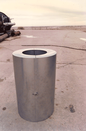 Figure 1
A single Reflective Metal Insulation (RMI) cassette for pipe insulation. This cassette consists of two semi-cylindrical cylinders, as with other types of pre-formed pipe insulation, that are held together with several latches.
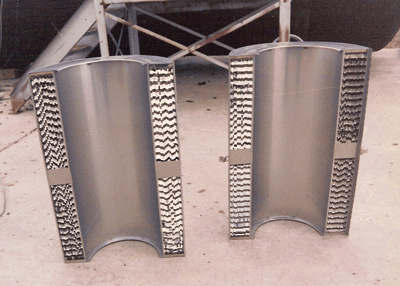 Figure 2
One of two halves of the RMI cassette shown in Figure 1. Note the concentric layers of stainless steel foil on the inside of the RMI insulation piece. This type of insulation is typically pre-engineered to fit in a particular location in the nuclear plant.
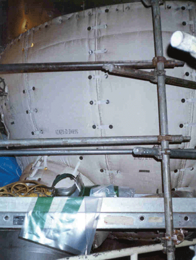 Figure 3
Pre-engineered, removable/reusable fiberglass blanket insulation inside a nuclear containment. These blankets are typically held in place with hook and loop fasteners. After complete installation, this type of insulation blanket is typically covered with removable/reusable stainless jacketing that uses latches for attachment.
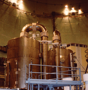 Figure 4
An insulation system consisting of pre-engineered, removable/reusable fiberglass blanket insulation with stainless steel jacketing.
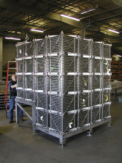 Figure 5
A new safety strainer, constructed for use at a Pressurized Water Reactor (PWR) nuclear plant, being inspected in the fabrication shop.

