Using Insulating Firebricks to Maximize Energy Savings in Iron and Steel Applications
Engineering design and the lining materials chosen are key factors in controlling the efficiency and energy usage of equipment used in iron and steel applications. Thus, it is critical that industrial designers understand the advantages and disadvantages of the materials they choose. One option for lining material is insulating firebricks (IFBs), which can minimize energy losses. Recent studies conducted on IFBs using the 3 most common manufacturing methods—cast, slinger, and extrusion—show that the cast process offers the lowest thermal conductivity and provides the greatest energy savings.
IFB Manufacturing Techniques Vary Widely in Ability to Control Energy Losses
IFBs are used in numerous iron and steel applications, including: blast furnace stoves, ductwork in direct reduction processes and reheat furnaces, back-up insulation in coke ovens, and tundishes and ladles. They are also used extensively to form the sidewalls, roofs, and hearths of a wide variety of heat treatment, annealing, and galvanizing lines. Figure 1 below shows their use in a coke oven stack (left) and in a tunnel kiln (right).
IFBs are manufactured using a variety of techniques, the most common of which are casting, slinger, and extrusion. The cast process uses gypsum plaster as a rapid setting medium for a high water content clay mix, containing additional burnout additives. The slinger process is a form of low-pressure extrusion of a wet clay mix containing high levels of burnout additives, with an additional processing step in which the semi-extruded material gets ‘slung’ onto a continuous belt to generate additional porosity before drying and firing. The extrusion process forces a damp clay mixture containing burnout additives through an extrusion nozzle, where the extruded material is subsequently cut into bricks, dried, and fired.
The brick chemistries and microstructures produced can vary significantly among these methods, leading to a wide variety of thermal conductivities within products of the same temperature rating. This variation in turn has an effect on the ability of different IFB types to control energy loss.
Study Conducted to Compare Manufacturing Methods
To understand the effect of the 3 main IFB manufacturing methods on thermal conductivity and energy loss behavior, researchers conducted a study to quantify the differences in energy usage that can be achieved within Class 23 (up to 2300°F) and Class 26 (up to 2600°F) IFBs.
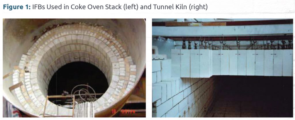

Figure 2 above shows the thermal conductivity of the IFBs tested; thermal conductivity is a critical property since IFBs are primarily used for their insulating abilities. In each class of IFB, cast brick has the lowest thermal conductivity, followed by the slinger-produced brick, with the extruded brick displaying the highest conductivity.
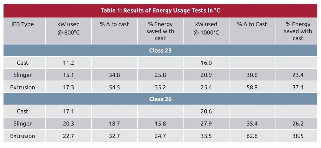
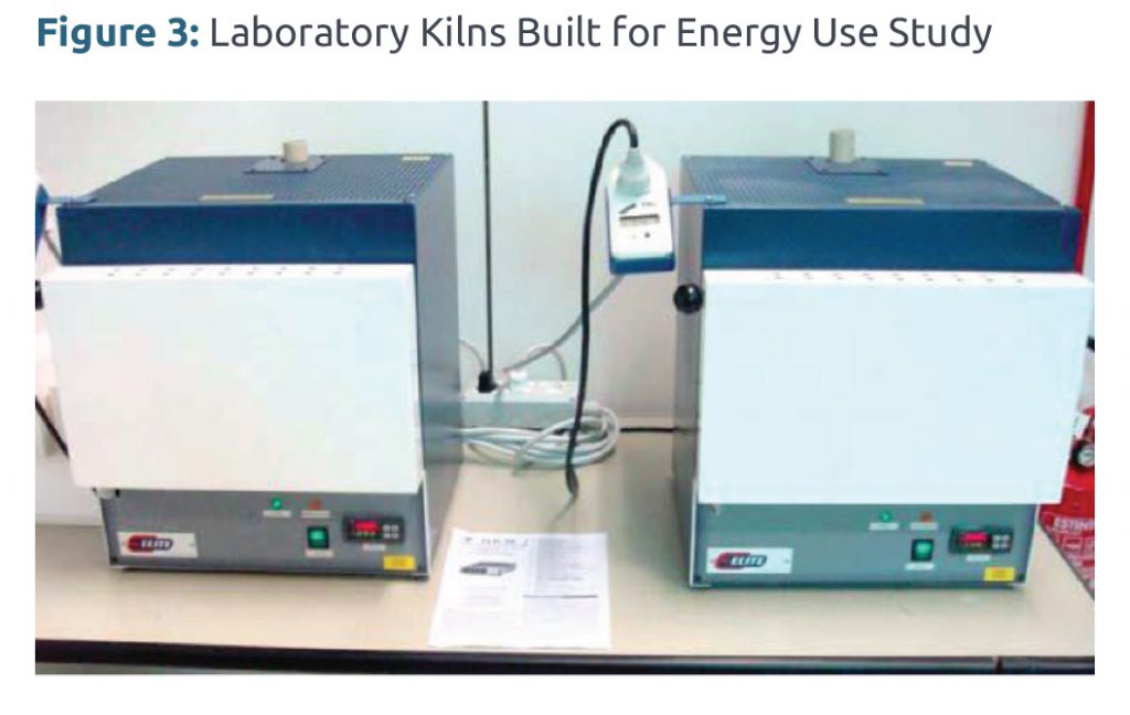
Researchers designed 2 identical electrically heated laboratory muffle kilns (shown in Figure 3) and conducted energy usage studies comparing the IFB brick types. They lined the first kiln with Class 23 cast IFBs and this formed the benchmark, since they had the lowest thermal conductivity in the class. The test results are shown in Table 1 below.
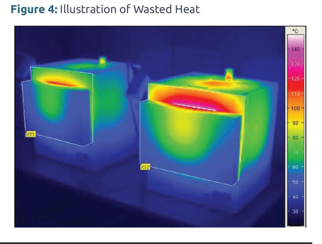
Figure 4 is a thermograph of the kilns during the 1000°C (1832°F) firing test; the cast IFB-lined kiln is on the left. It shows how much heat is wasted through the body of the kiln lined with the higher thermal conductivity IFBs and how the surface temperature of the kiln becomes overheated. This shows both the effect of wasting energy costs and health and safety issues caused by hazardous working temperatures.
Significantly less energy was needed to run the test kiln through a 1000°C (1832°F) firing cycle with the cast IFBs compared to the extrusion IFBs (37% less for Class 23 and 38.5% less for Class 26). These energy usage differences are due to the differing thermal conductivities of the IFBs. In materials of similar chemistry, thermal conductivity is controlled by the structure of the material. The different manufacturing methods of the IFBs studied produce materials with inherently different macro- and microstructures, which control the thermal behavior of the products. For example, Figure 5 on page 11 illustrates the differing macrostructures of the Class 23 IFBs studied. The texture of the IFBs is finest for the cast product and is coarsest for the extruded product.
Energy-Saving Calculations
After conducting laboratory tests demonstrating the potential to minimize energy usage through appropriate selection of IFBs for an installation lining, researchers then ran heat flow calculations to understand the effect on actual industrial installations. Calculations were done to assess energy-running costs in strategic locations of 2 annealing applications that use IFBs as the lining material: a catenary strip–annealing furnace and a cast iron part-annealing furnace.
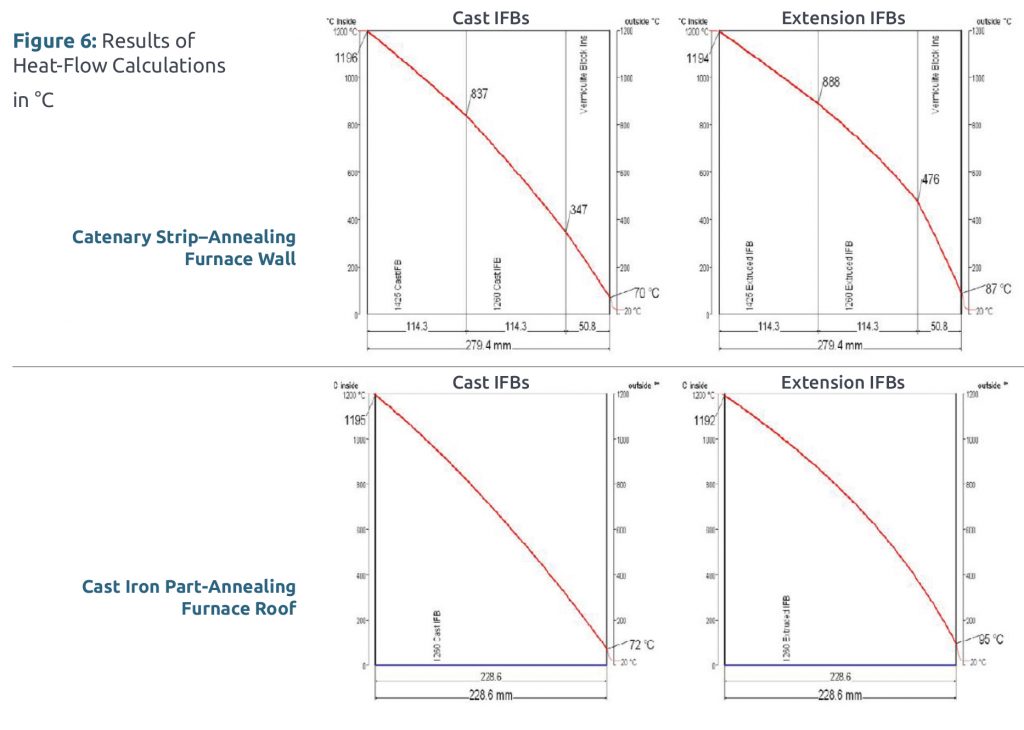
The modeling was performed using the most common real life IFB-lining arrangements, where walls are normally built up using standard brick sizes, while roofs are constructed from special pre-assembled roof blocks. Figure 6 on page 13 shows the results. The top graphs show heat flow calculations for the catenary strip–annealing furnace wall using cast IFBs (left) and extrusion IFBs (right). The bottom shows heat flow calculations for the cast iron part-annealing furnace roof using cast IFBs (left) and extrusion IFBs (right).
Table 2 on page 12 shows the significant differences that can be achieved for casing temperatures when using different IFB types. Using cast IFB produces much lower casing temperatures than with extruded IFB. The lower surface temperature obtained using the cast IFB also produces a more comfortable working environment for operators and minimizes the risk of burns due to operators coming into contact with the surface of the installation.
The heat flow calculations show that for the catenary strip–annealing furnace wall, the lining with the extrusion IFBs requires 271 W/m2 (86 Btu/m2)more energy to maintain the 1200°C (2192°F) operating temperature than the lining with the cast IFBs, due to the lower thermal conductivity of the cast compared to the extruded IFBs. The difference in energy consumption between the 2 simulated furnace walls equates to a saving of 42,450 m3 (1.5MM ft3) of natural gas per year using the cast IFBs compared to the extrusion IFBs. Assuming a gas price of $0.192/m3 ($0.00544 ft3), this equates to an annual saving of $8,150/year for this wall section only. Assuming a furnace wall lining life of 10 years, the total saving over the life of the kiln lining would be $81,500.

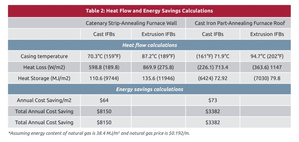
The savings on the complete structure would be significantly larger. A 127 m2 (1367 ft2) working area in the wall of the catenary strip–annealing furnace would need approximately 7,200 standard-sized IFBs. Although the cast IFB price is a little higher, the example shows an initial payback period of just over 3 months; for the rest of the 10-year service life, there would be continuous cost savings due to the lower energy requirements.
For the cast iron part-annealing furnace roof, the lining with the extrusion IFBs requires 434 W/m2 (137.5 Btu/ft2) more energy to maintain the 930°C (1706°F) operating temperature than the lining with the cast IFB. For the 46.5 m2 (500.6 ft2) working area, the difference in energy consumption between the 2 simulated furnace roofs equates to a saving of 17,615 m3 (0.63MM ft3) of natural gas per year using the cast IFBs compared to the extrusion IFBs, which equates to an annual saving of $3,382 per year for just this small roof section. Assuming a furnace roof lining life of 10 years, the total saving over the life of the kiln lining would be $33,820. The savings on the complete structure would be significantly higher. The 46.5 m2 (500.6 ft2) roof area would need approximately 2,600 standard sized IFBs, so the payback for using cast IFBs is less than 3 months.
Follow Guidelines to Minimize Heat Loss
By monitoring energy usage in laboratory kilns lined with IFBs manufactured by different process routes, and by modeling the effects on heat flow of using IFBs manufactured by different processes in 2 important iron and steel applications, research has demonstrated that IFBs manufactured by the cast process offer the lowest thermal conductivity available today at application temperatures and provide the greatest energy savings.
This article was published in the January 2016 issue of Insulation Outlook magazine. Copyright © 2017 National Insulation Association. All rights reserved. The contents of this website and Insulation Outlook magazine may not be reproduced in any means, in whole or in part, without the prior written permission of the publisher and NIA. Any unauthorized duplication is strictly prohibited and would violate NIA’s copyright and may violate other copyright agreements that NIA has with authors and partners. Contact publisher@insulation.org to reprint or reproduce this content.
