Using Thermal Imaging to Improve Systems
Facility managers may assume that mechanical insulation on equipment and systems will remain intact and perform indefinitely; however, this is not always the case. Factors like damage, neglect, and aging, can dramatically impact the integrity of mechanical insulation. Periodic inspections can detect these unfavorable conditions and allow you to diagnose potential problems. Taking advantage of available predictive maintenance techniques can have a significant impact on the overall efficiency, as well as the operating budget of your facility.
One such technique is thermal imaging or thermography. Thermal imaging is a non-destructive testing (NDT) technique that can identify problem areas of insulation without removing it. The infrared (IR) camera detects heat (infrared energy) and captures a thermal image (thermogram) that can be used to determine where energy is being lost.
A trained thermal camera technician or thermographer can inspect large sections of the insulation with this simple handheld instrument. Insulation is designed to reduce conduction from the equipment into the atmosphere. The energy that goes through the insulation to the surface may then radiate from this last surface—this is the energy that an IR camera images. Using thermal imaging to detect this escaping energy has many benefits including: reducing energy loss, controlling temperatures, reducing condensation and corrosion, extending equipment life, reducing downtime, and increasing plant safety.
How the IR Camera Works
Understanding how an IR camera detects heat and the science behind it is necessary to accurately capture and interpret thermal images. Human eyes can only see electromagnetic radiation that lies within the visible light spectrum. Since infrared radiation is outside that spectrum, it is invisible. So while we may physically feel heat (infrared energy) radiating from a pipe, we cannot see it. However, when a thermographer captures an infrared image of the pipe, the thermal camera detects this radiant energy being emitted, translating it into colors of the visible light spectrum—colors that we can see.
Infrared cameras have a feature that allows the user to select color palettes depending on the specific application. While a gray palette is great for fine detail and pattern recognition, it is not as good for discerning temperature differences. A rainbow palette displays greater high and low thermal contrast, making it easier to interpret the temperature differences found within the thermal image.
Depending on the choice of palette, the camera assigns colors to radiation intensity variations, providing a heat map and displaying a temperature scale. White and red are the hottest temperatures; yellow is intermediate; violet and blue show cooler temperatures; and black identifies the coldest areas of the thermal image.
Keep in mind, these temperatures can be misleading. A thermal camera detects radiant (heat) energy, not temperature, and there are various factors that affect temperature readings. These factors include accurately adjusting the thermal camera functions and parameters, as well as correcting for conditions related to the material and type of surface being imaged (e.g., emissivity and reflected energy from background.)
Interpreting the Image
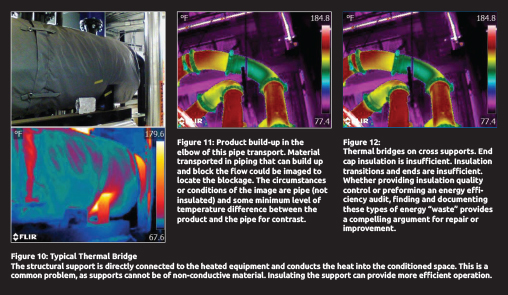
Correct interpretation of a thermal image also involves having a clear understanding of the material at the surface, the material beneath the surface, and finally the energy level that is being insulated in the first place. What this all means is that the camera is seeing the heat transferring from the heated or cooled equipment through the insulation material to the outer surface. The energy will always find the quickest—or in some ways the most efficient—means to transfer. When a thermal camera is imaging the energy flow through the insulation material, any pattern discrepancy will be the focus of the interpretation. Inconsistent patterns are flags for further investigation or explanation. See Figure 1 on page 25 for a visual example.
Understanding Settings
While the increased functionality of today’s thermal cameras makes it easier to get high image resolution and more accurate temperature calculations, knowing how to get these results requires some skill. Many mistakes can be avoided by learning how to use basic camera functions and understanding its parameters. Appropriately adjusting settings such as focus, range, distance, thermal tuning, emissivity, etc. plays a critical role in capturing a useful thermal image. While some of the adjustments can be done in the software after downloading the image, it is important to adjust those that must be made before saving the image.

The following settings cannot be adjusted after saving the image:
- Focus—There are a variety of thermal cameras on the market today. Manual focus cameras have adjustable lenses. These require time and practice to learn the adjustments necessary to capture a clear image. Some cameras have auto focus that automatically adjusts the lens for a sharp image. Fixed focus cameras cannot be adjusted; however, as with any camera, movement can cause clarity problems. Many fixed focus cameras also have lower resolution and/or wide angle lenses that compound problems. Regardless of whether a camera has auto, manual, or fixed focus—it must be in focus to produce accurate temperature measurements.
- Temperature Ranges—Most cameras allow the user to select a temperature range. The temperature range shows the minimum and maximum temperatures that the thermal camera can measure. This range is typically -20°C to 1500°C. The range determines the limits of accurate measurements. The user must be knowledgeable of the settings and conditions (e.g., emissivity and reflected apparent temperatures) when deciding whether a narrow or broad range setting would capture a more accurate temperature.
- Distance (Physical) or Spot Size Ratio (SSR)—Thermal cameras can accurately measure temperatures from a distance, but only if the user can determine the correct distance to the object ratio. SSR is a method for determining the best distance of the camera from the target to obtain an accurate temperature reading. If a measurement is a necessary part of the subsequent evaluation, then the size of the pipe and the distance from it becomes an important consideration. The rule is just because it can be imaged, does not mean it can be measured.
The following settings can be changed in the software after the image is saved:
- Thermal Tuning—This function refers to adjusting the level (thermal brightness) and span (thermal contrast) to optimize or “tune” the thermal image. Having the ability to adjust the contrast and brightness of an image to aid the clarity becomes essential to properly provide a clear pattern and origination point of where the energy is appearing. It can be difficult to know when the image is properly tuned. A general rule to follow is when the object of interest and the pattern of interest is clearly defined without saturation of very hot appearance or very cold, the image should clearly demonstrate the items of interest. See an improperly and properly tuned image in Figures 5 and 6.
- Emissivity—The user must adjust the camera settings based on the emissivity values of an object. Emissivity is the amount of radiation emitted from an object’s surface—how reflective the surface is. Factors like thickness, coatings, and material types have to be taken into consideration. For example, a highly reflective object has low radiant effectiveness or low emissivity, so a lower emissivity setting should be used. Conversely, a high emissivity setting should be used with a low-reflective object.
Caveats
Using thermal imaging in mechanical insulation inspections is not without limitations. Some limitations relate to camera functionality—such as resolution—and others depend on user skills (e.g., focusing and tuning). However, the most problematic factor in thermal imaging is accurately assessing the surface that radiates low emissivity. Bare metal over wraps and sheathed protection may have a property of low-radiant effectiveness or low emissivity that can result in unpredictable, strange, and inaccurate readings.
Surfaces that do not radiate energy well reflect the environment surrounding that equipment. A simple solution would be to cover those surfaces—as much as is possible—with another material such as a thin cloth or tack paper when using the camera. Painting or coating an area would be a more permanent solution. This will raise the surface emissivity to more effectively radiate efficiency value.
Using a single inspection tool like thermal imaging may have some limitations, but when used in conjunction with other inspection techniques, developing problems can be cross-diagnosed. This approach to predictive maintenance proves to be much more thorough.

Thermal Imaging Survey
Thermal imaging can turn an inspection into a checklist of system integrity—highlighting suspect areas and resulting in the elimination of problems with the insulation system—or preventing them all together. A thermal imaging survey can be a non-destructive, cost-effective tool to improve facility energy audits and increase energy efficiency. Further, the plant will be drier, quieter, and safer. If your plant chooses to do a systematic insulation review, the following steps are recommended:
- Use knowledgeable, trained technicians that understand systems and infrared cameras.
- Have a systemic approach for data collection.
- Use plant personnel for access and system identification.
- Image a complete system as much as possible. Avoid the tendency to do a wander-type survey.
- Record image data by plant identification or tagging.
- Image equipment from multiple angles to obtain a complete interpretation.
- Visual images are just as important as thermal.
- Be certain of system temperatures and conditions. An ambient pipe in an ambient environment will not produce enough contrast to image problems.
- Be aware of low emissivity or bare metal surfaces. These can confuse real problems and produce false patterns.
- Produce a formal report for accuracy in repair dispatch and also for return on investment (ROI) estimates for repairs.

Thermal imaging lends itself to mechanical insulation inspection. It can provide meaningful data for energy calculations that will improve the efficiencies of insulation systems. With training and practice, your personnel will be able to capture accurate thermal images, interpret them correctly, and use them in predictive maintenance assessments.
Whatever the end-goal or purpose of the inspection—maintenance, safety, commissioning verification, energy efficiency, or production improvement—thermal imaging is a valuable tool for assessing the overall effectiveness of an insulation system.
Copyright Statement
This article was published in the October 2016 issue of Insulation Outlook magazine. Copyright © 2016 National Insulation Association. All rights reserved. The contents of this website and Insulation Outlook magazine may not be reproduced in any means, in whole or in part, without the prior written permission of the publisher and NIA. Any unauthorized duplication is strictly prohibited and would violate NIA’s copyright and may violate other copyright agreements that NIA has with authors and partners. Contact publisher@insulation.org to reprint or reproduce this content.
Jay Bowen
Jay Bowen, ASNT NDT Level III TIR, is a BPI Certified Building Analyst and has been enthusiastically assisting clients in thermography applications for many decades. Bowen & Associates, LLC (www.boweninfrared.com) offers a complete process of training and implementation. Mr. Bowen can be reached at jay.bowen@boweninfrared.com.
Related Articles
Every Picture Tells a Story
Thermography has become an invaluable asset for insulation energy audits
Read Article
