Category Archives: Global

IO160303_01
IO160303_02
IO160303_03

Refractory has always been an integral part of boiler design. However, because it is one of the smallest of the boiler components, it sometimes does not get the attention it deserves. Paying attention to the refractory material selection on new or existing boilers can and will help ensure efficient boiler operation and contribute to energy savings (from using less fuel) as well as preventing unnecessary steam-generation interruption.

Due to the recent Environmental Protection Agency (EPA) rules regulating emission levels, it has been reported that more than 32 power plants will be closed around the United States, with possibly another 36 in the near future. Though this is a significant number, it still leaves approximately 3,100 power plants operating in the United States that burn coal, gas, oil, and other fuels, generating approximately 900,000 megawatts of electricity (excluding hydroelectric and nuclear). These boilers, by design, are typically flat studded, tangential (inner cased), or membrane-tube type boilers. Most are insulated with mineral wool board insulation meeting ASTM C-612 type IVB and require refractory to help keep them energy efficient by keeping the fire inside the boiler.

A flat-studded boiler has tube walls on approximately 6-inch centers with a 1-inch thick layer of refractory covering the outside of the boiler-furnace tubes. Tangential or inner cased boilers have even more tubes, are tangent to each other, and require only a smear coat of refractory between the tubes. A membrane boiler uses smaller diameter tubes that are shop welded together into panels with a bar between the tubes. This bar is termed “membrane” (refractory is not required between or over the membrane tubes).

IO160303_04
IO160303_05

All of these types of boilers are similar in that they make steam and generate electricity. They differ by the fuel they burn (trash, wood, coal, oil, or gas). The type of refractory required will depend on the location of the refractory install area and in some cases, by the fuel being burned. For example, the refractory found inside the boiler will be exposed to higher temperature, flue gases, ash, slag, and the stoichiometry
of the burners—all of which is created by the fuels being burned, thereby requiring a more specialty type of refractory.

IO160303_06
IO160303_07

Refractory

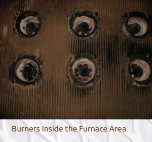
The term refractory in the boiler industry can refer to either a plastic or a castable-type material. According to withdrawn standard ASTM C-64, a plastic refractory is divided into 5 basic categories: high-duty fireclay, super-duty fireclay, 60% alumina, 70% alumina, and 80% alumina. A plastic material will be made from either fireclay or alumina with the balance made from other materials. The use of plastic refractory in the power industry is quite rare, since these types of products are very dense, cost more than other conventional-type refractory products, and are normally hand or pneumatically rammed. Plastic refractory tends to be used only in a specialty area of the boiler. A plastic refractory material is generally found inside the boiler furnace and is designed to resist higher temperatures and chemical or abrasive attack.

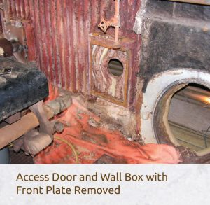
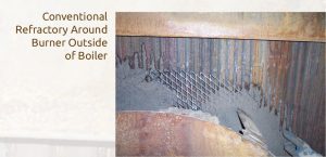
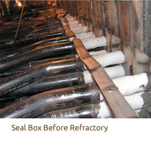
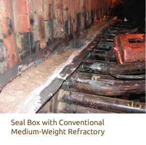
According to ASTM C-64, castable or conventional refractory is divided into 2 classifications: alumina-silica-base or an insulating-type refractory. In the boiler industry, a castable refractory (alumina-silica or insulating) is more commonly used than a plastic refractory. A castable refractory is generally used for common seals, tube penetrations, and for filling wall-box applications. This type of refractory is the most commonly found refractory on all boilers; it is used on the outside of the steam-generating boilers and is not used inside the boiler/furnace area.

IO160303_08
IO160303_09
IO160303_10

A specialty-type refractory material also falls under ASTM C-64 and can be either a plastic or castable and covers a wide range of products and uses. Some are designed to resist thermal shock, slag resistance, erosion, or a combination of these. Unlike conventional refractory, a specialty-type product will have higher alumina content (Al2O3) or silicon carbide (SiC) as its base material, low or no calcium oxide (CaO), and have additional chemicals such as chromium oxide (Cr2O3) or zirconium (ZrO2). Specialty refractory materials are the exception and not the norm in the boiler industry.

To simplify, in the boiler industry for non-specialty areas, there are 3 basic or conventional types of refractory: dense, medium, and lightweight.

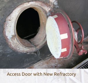
  • Dense refractory materials have a density greater than 160#/cf and are used around access doors or burner throats.
  • Medium weight refractory materials have a density between 100#/cf to 160#/cf and are used for sealing between tubes, filling wall boxes, ash hoppers, and tube penetrations.
  • Lightweight or insulating-type refractory materials have a density less than 100#/cf and are rarely used except in access doors.

All 3 types use the same common chemicals, yet each varies considerably to meet their specific use requirement. The most common chemicals for a cement bonded refractory material are: alumina (Al2O3); silica (SiO2); ferric oxide (Fe2O3), which is sometimes referred to as iron oxide; titanium oxide (TiO2); calcium oxide (CaO), which is sometimes referred to as cement or lime; magnesium oxide (MgO); and alkalies such as sodium (Na2O) and potassium (K2O). A phosphate-bonded material would have phosphorus pentoxide (P2O5) in lieu of calcium oxide (CaO). All basic or conventional refractory materials are primarily used to prevent gas and fire from escaping from the boiler furnace.

Selecting a refractory type should be based on the area of usage, the temperature, and the operating conditions it will be exposed to, such as flue gas, slag, and ash (if located inside the boiler/furnace area). The aforementioned criteria should play a primary role in which material is selected, but it is also important to consider the installation of the material before the final selection is made. Each refractory material has unique qualities. Some refractory material can only be installed in one particular way (e.g., shotcrete, gunned, troweled, pumped, or poured). It is very important to consider all factors before you finalize your material selection. The following is an example of a power company failing to take all factors into consideration before selecting a refractory type.

Consider the following example: Power Company “A” had 5 duplicate coal-fired boilers that are non-membrane type and require a thick layer of refractory inside the boiler on the furnace floor tubes. The plant had been using the same refractory material for many years and had reasonable success in keeping the refractory lining inside their boiler for 3 years or longer between replacements. Then, the management decided to (1) operate their boilers only during peak hours (this is called cycling); (2) ramp and cool down their boilers at an excessive ramp rates; and (3) change to a cheaper coal type or blend (i.e., 80/20 to 100%, Eastern versus Powder River Basin) to help lower their cost for generating electricity. They made these decisions without first considering the impact of the refractory material used inside their boilers and assumed that the same refractory would work fine.

The power company failed to realize these 3 important issues:

  1. Cycling a boiler can cause internal stress within the refractory, which weakens the strength of the material and reduces the life expectancy of the lining.
  2. Rapid start up and shut downs can cause internal stress within the refractory, which weakens the strength of the material and reduces the life expectancy of the lining.
  3. Making a fuel change for generation cost savings without first doing a complete fuel and refractory analysis study will increase the risk of a refractory failure.

The impact of these changes in operation and fuel was immediate as the refractory materials inside each of their boilers began to fail (erode or otherwise disappear). In less than 12 months, the refractory for all boiler floors were replaced using an assortment of different refractory products with each only lasting about 1 year. Then, the power company made another management decision and changed the fuel again, this time to a different coal blend. This immediately caused complete and total failure of the refractory lining in less than 1 month.

Each refractory failure cost the power company more than $150,000, not including removal of any existing refractory remaining on the floor, plus the dollars associated with not generating any steam to make electricity. Choosing a refractory material at random while still cycling the boiler, and not going back to the original coal type and blend, cost the power company almost a million dollars. The fuel and generation cost savings they expected and the realities of the refractory replacement costs could impact the power plant’s very existence.

Refractory has been a major contributor to boiler operation and energy savings. Though refractory may be one of the smallest of the components that make up a power-generation facility, it pays to pay attention to refractory. It is important to choose a refractory type based on current operating conditions. If in doubt, ask a local contractor or material supplier for assistance. Using the right refractory material to meet your boiler operation will save money and reduce maintenance costs, and will also protect the system.

References

  1. ASTM International, “Specification for Fireclay Brick Refractories for Heavy Duty Stationary Boiler Service” ASTM C64-72, ASTM International, (1977).
  2. F.H. Norton, Refractories (McGraw Hill Book Company, 1949).


Copyright Statement

This article was published in the March 2016 issue of Insulation Outlook magazine. Copyright © 2016 National Insulation Association. All rights reserved. The contents of this website and Insulation Outlook magazine may not be reproduced in any means, in whole or in part, without the prior written permission of the publisher and NIA. Any unauthorized duplication is strictly prohibited and would violate NIA’s copyright and may violate other copyright agreements that NIA has with authors and partners. Contact publisher@insulation.org to reprint or reproduce this content.

Engineering design and the lining materials chosen are key factors in controlling the efficiency and energy usage of equipment used in iron and steel applications. Thus, it is critical that industrial designers understand the advantages and disadvantages of the materials they choose. One option for lining material is insulating firebricks (IFBs), which can minimize energy losses. Recent studies conducted on IFBs using the 3 most common manufacturing methods—cast, slinger, and extrusion—show that the cast process offers the lowest thermal conductivity and provides the greatest energy savings.

IFB Manufacturing Techniques Vary Widely in Ability to Control Energy Losses

IFBs are used in numerous iron and steel applications, including: blast furnace stoves, ductwork in direct reduction processes and reheat furnaces, back-up insulation in coke ovens, and tundishes and ladles. They are also used extensively to form the sidewalls, roofs, and hearths of a wide variety of heat treatment, annealing, and galvanizing lines. Figure 1 below shows their use in a coke oven stack (left) and in a tunnel kiln (right).

IFBs are manufactured using a variety of techniques, the most common of which are casting, slinger, and extrusion. The cast process uses gypsum plaster as a rapid setting medium for a high water content clay mix, containing additional burnout additives. The slinger process is a form of low-pressure extrusion of a wet clay mix containing high levels of burnout additives, with an additional processing step in which the semi-extruded material gets ‘slung’ onto a continuous belt to generate additional porosity before drying and firing. The extrusion process forces a damp clay mixture containing burnout additives through an extrusion nozzle, where the extruded material is subsequently cut into bricks, dried, and fired.

The brick chemistries and microstructures produced can vary significantly among these methods, leading to a wide variety of thermal conductivities within products of the same temperature rating. This variation in turn has an effect on the ability of different IFB types to control energy loss.

Study Conducted to Compare Manufacturing Methods

To understand the effect of the 3 main IFB manufacturing methods on thermal conductivity and energy loss behavior, researchers conducted a study to quantify the differences in energy usage that can be achieved within Class 23 (up to 2300°F) and Class  26 (up to 2600°F) IFBs.

IO160101_01
IO160101_02

Figure 2 above shows the thermal conductivity of the IFBs tested; thermal conductivity is a critical property since IFBs are primarily used for their insulating abilities. In each class of IFB, cast brick has the lowest thermal conductivity, followed by the slinger-produced brick, with the extruded brick displaying the highest conductivity.

Researchers designed 2 identical electrically heated laboratory muffle kilns (shown in Figure 3) and conducted energy usage studies comparing the IFB brick types. They lined the first kiln with Class 23 cast IFBs and this formed the benchmark, since they had the lowest thermal conductivity in the class. The test results are shown in Table 1 below.

Figure 4 is a thermograph of the kilns during the 1000°C (1832°F) firing test; the cast IFB-lined kiln is on the left. It shows how much heat is wasted through the body of the kiln lined with the higher thermal conductivity IFBs and how the surface temperature of the kiln becomes overheated. This shows both the effect of wasting energy costs and health and safety issues caused by hazardous working temperatures.

Significantly less energy was needed to run the test kiln through a 1000°C (1832°F) firing cycle with the cast IFBs compared to the extrusion IFBs (37% less for Class 23 and 38.5% less for Class 26). These energy usage differences are due to the differing thermal conductivities of the IFBs. In materials of similar chemistry, thermal conductivity is controlled by the structure of the material. The different manufacturing methods of the IFBs studied produce materials with inherently different macro- and microstructures, which control the thermal behavior of the products. For example, Figure 5 on page 11 illustrates the differing macrostructures of the Class 23 IFBs studied. The texture of the IFBs is finest for the cast product and is coarsest for the extruded product.

IO160101_03
IO160101_04
IO160101_05

Energy-Saving Calculations

After conducting laboratory tests demonstrating the potential to minimize energy usage through appropriate selection of IFBs for an installation lining, researchers then ran heat flow calculations to understand the effect on actual industrial installations. Calculations were done to assess energy-running costs in strategic locations of 2 annealing applications that use IFBs as the lining material: a catenary strip–annealing furnace and a cast iron part-annealing furnace.

The modeling was performed using the most common real life IFB-lining arrangements, where walls are normally built up using standard brick sizes, while roofs are constructed from special pre-assembled roof blocks. Figure 6 on page 13 shows the results. The top graphs show heat flow calculations for the catenary strip–annealing furnace wall using cast IFBs (left) and extrusion IFBs (right). The bottom shows heat flow calculations for the cast iron part-annealing furnace roof using cast IFBs (left) and extrusion IFBs (right).

Table 2 on page 12 shows the significant differences that can be achieved for casing temperatures when using different IFB types. Using cast IFB produces much lower casing temperatures than with extruded IFB. The lower surface temperature obtained using the cast IFB also produces a more comfortable working environment for operators and minimizes the risk of burns due to operators coming into contact with the surface of the installation.

The heat flow calculations show that for the catenary strip–annealing furnace wall, the lining with the extrusion IFBs requires 271 W/m2 (86 Btu/m2)more energy to maintain the 1200°C (2192°F) operating temperature than the lining with the cast IFBs, due to the lower thermal conductivity of the cast compared to the extruded IFBs. The difference in energy consumption between the 2 simulated furnace walls equates to a saving of 42,450 m3 (1.5MM ft3) of natural gas per year using the cast IFBs compared to the extrusion IFBs. Assuming a gas price of $0.192/m3 ($0.00544 ft3), this equates to an annual saving of $8,150/year for this wall section only. Assuming a furnace wall lining life of 10 years, the total saving over the life of the kiln lining would be $81,500.

IO160101_06
IO160101_07

The savings on the complete structure would be significantly larger. A 127 m2 (1367 ft2) working area in the wall of the catenary strip–annealing furnace would need approximately 7,200 standard-sized IFBs. Although the cast IFB price is a little higher, the example shows an initial payback period of just over 3 months; for the rest of the 10-year service life, there would be continuous cost savings due to the lower energy requirements.

IO160101_08

For the cast iron part-annealing furnace roof, the lining with the extrusion IFBs requires 434 W/m2 (137.5 Btu/ft2) more energy to maintain the 930°C (1706°F) operating temperature than the lining with the cast IFB. For the 46.5 m2 (500.6 ft2) working area, the difference in energy consumption between the 2 simulated furnace roofs equates to a saving of 17,615 m3 (0.63MM ft3) of natural gas per year using the cast IFBs compared to the extrusion IFBs, which equates to an annual saving of $3,382 per year for just this small roof section. Assuming a furnace roof lining life of 10 years, the total saving over the life of the kiln lining would be $33,820. The savings on the complete structure would be significantly higher. The 46.5 m2 (500.6 ft2) roof area would need approximately 2,600 standard sized IFBs, so the payback for using cast IFBs is less than 3 months.

Follow Guidelines to Minimize Heat Loss

By monitoring energy usage in laboratory kilns lined with IFBs manufactured by different process routes, and by modeling the effects on heat flow of using IFBs manufactured by different processes in 2 important iron and steel applications, research has demonstrated that IFBs manufactured by the cast process offer the lowest thermal conductivity available today at application temperatures and provide the greatest energy savings.


This article was published in the January 2016 issue of Insulation Outlook magazine. Copyright © 2017 National Insulation Association. All rights reserved. The contents of this website and Insulation Outlook magazine may not be reproduced in any means, in whole or in part, without the prior written permission of the publisher and NIA. Any unauthorized duplication is strictly prohibited and would violate NIA’s copyright and may violate other copyright agreements that NIA has with authors and partners. Contact publisher@insulation.org to reprint or reproduce this content.

Sound waves generated in industrial environments add up to noise that can be reduced with insulation.

Industrial insulation is generally thought of in terms of thermal performance, but an important, secondary benefit of insulation is its contribution to noise control. In many cases, properly engineered industrial insulation systems can be used to reduce the noise level of loud pipes, equipment, and systems.

What we describe as sound is simply a vibration (mechanical pressure wave) that travels through a medium (e.g., gas, liquid or solid). Sound waves move longitudinally away from the source, just like water ripples away from a disturbance on its surface. For example, dropping a pebble into a pool of water will cause ripples to move outward, away from the disturbance. Sound waves travel in this very same manner.

Sound is described in terms of several different characteristics, such as level (what we would interpret as loudness) and frequency. Level is measured in decibels (dB) and describes how much sound there is. Frequency is simply cycles per second, measured in “Hertz” (Hz). Frequency ranges for industrial environments can be described as a hiss (high frequency, 1000-8000Hz), a roar (mid-frequency, 125-500Hz), or a rumble (low frequency, 31-63Hz). In cases where ambient noise exceeds 85 dB, hearing protection is required to reduce the potential for long-term hearing loss.

The Basics of Sound Control

In an industrial environment, we are concerned with 2 types of sound control: sound absorption and sound transmission. Sound absorption can be used to reduce reverberation in the industrial environment where hard, flat surfaces reflect sound. The results of sound absorption testing (ASTM C423) provide a Noise Reduction Coefficient (NRC) value. Generally speaking, a product with an NRC value of 0.75 would absorb 75% of the sound that strikes its surface while reflecting the remaining 25%. The higher the NRC value, the more sound is absorbed. Some of the best sound absorbers are open cell materials, such as fibrous insulations. This is because the dense fibrous structure dissipates sound by absorbing sound waves and then converting them into a small amounts of friction energy.

When too much sound is passing through a system, like pipe wall or equipment housings, sound transmission treatments are effective solutions for reducing noise. Adding weight and thickness to the system lessens the amount of sound traveling through the system, thus reducing the ambient noise level outside of the pipe or equipment. The more weight a system has, the more energy it takes to vibrate the system. Generally speaking, the thicker the insulation system is, the easier it is to dampen the mid-frequency (roar) and high-frequency (hiss) noise that radiates from the system. The best insulation materials for reducing sound transmission are heavier, thicker insulations.

Finally, installation requirements for thermal applications apply to acoustical applications as well. Since sound can be transmitted through small openings and cracks, care should be taken to install the insulation so that it completely covers the pipe or equipment to prevent the radiation of sound. Although it is difficult to eliminate all noise in an industrial environment, small changes can provide measurable reductions in background noise levels.


Copyright Statement

This article was published in the January 2016 issue of Insulation Outlook magazine. Copyright © 2016 National Insulation Association. All rights reserved. The contents of this website and Insulation Outlook magazine may not be reproduced in any means, in whole or in part, without the prior written permission of the publisher and NIA. Any unauthorized duplication is strictly prohibited and would violate NIA’s copyright and may violate other copyright agreements that NIA has with authors and partners. Contact publisher@insulation.org to reprint or reproduce this content.

On the design table, many insulation materials can work for a variety of piping and tank applications; design considerations often include insulating value, fire safety, resistance to corrosion, and other factors. However, planning must also take into account real-world conditions that may be likely to occur, such as freeze/thaw cycles, system movement, potentially crushing loads with direct burial, wash downs, or simply damage by workers.

Once an insulation system becomes damaged or absorbs moisture, the insulation enables accelerated heat gain or loss, increased energy consumption, and loss of process control; in cryogenic systems and high-temperature systems, solidification is also a concern. Damage or moisture can also lead to corrosion and be a potential danger to personnel. Selecting the right insulation for a project can make the difference between long-term performance and the need for replacement or retrofitting. It can also determine whether a system has constant thermal efficiency or expensive stoppage of production because gases turn to liquid or liquids turn to solids.

Moisture Is a Problem

Regardless of the application or temperature range, the most likely cause of damage to insulation is moisture. The vast majority of insulation system problems are caused by moisture, which typically enters through the jacketing and can be retained within in the insulation.

In the theoretical design stage, a permeable insulation will not absorb moisture if protected with the proper jacketing. However, in a critical application like chilled water—where there is a strong vapor drive from the air to the cold piping—even a small tear, crack, or pinhole can develop, allowing an entryway for damaging moisture in either liquid or vapor form. In high-temperature applications, this can become a personnel safety issue. The severity of moisture issues will depend partially on the temperature range of the system.

Cold/Cryogenic

While moisture can enter the system directly as absorbed water, an even more significant source of moisture penetration is diffusion of water vapor, which can condense as a liquid or ice. As the temperature gradient increases between the exterior insulation surface and the surface of the insulated equipment itself, so does the potential rate of water-vapor penetration. Thus, it is more important that the insulation has a low vapor-transmission rate than an initially low thermal conductivity.

High Temperature

Potential issues can arise in high-temperature systems when using a permeable insulation or relying on water-repellant treatments on the material. At these temperatures, an insulation can become completely saturated in less than a few hours. Also, most water-repellant treatments deteriorate and become ineffective at temperatures as low at 265°F. While process heat can drive water back to a certain point, some will always remain in the insulation layers that are below 212°F, resulting in substantial heat loss and a compromise in process control.

The best way to prevent damage to the system is to specify an impermeable insulation system that does not rely on vapor retarders and jacketing to keep moisture out of the system.

Accessories Are Important

While much emphasis is placed on the details of the physical and performance characteristics of the insulation material itself, the importance of accessory products is often overlooked.

Some view accessory products as commodities that can be mixed and matched. However, history and performance have proven that if high-quality, compatible accessories are not used, the performance and dependability of the entire insulation system can be compromised.

Taking a “total-system” approach to design can be the best way to ensure optimal operations. A total-system approach is simply using accessory components that have been tested and recommended as compatible for the specific insulation being used. This approach can best achieve the desired results of a high-quality, long-lasting insulation system.

Any coatings planned for use in a system should be tested for chemical resistance, weathering, and appearance. Adhesives and sealants need to be tested to perform with a specific insulation material to prevent water vapor entry, especially on below-ambient and cyclic systems, or systems subject to wash down. Again, the best way to reduce the threat of insulation failure due to moisture is to use an impermeable insulation product.

If the insulation material is impermeable, a jacketing is needed to provide mechanical protection on above-ground and below-ground installations. Metal jacketing provides mechanical protection on above-ground applications, while bituminous jackets prevent water and water-vapor intrusions in below-ground applications.

Preventing Corrosion under Insulation

One of the most critical problems caused by moisture is metallic corrosion under insulation (CUI). When water comes into contact with either carbon steel or stainless steel, corrosion or stress cracking can occur. This can remain undetected for years, hidden by the insulation and outer jacketing.

Unfortunately, CUI is often detected only after the equipment and insulation system have been damaged and need to be replaced. This can be a costly proposition as it is associated with downtime, lost productivity, and even total facility shutdown. In a worst-case scenario, sudden, dangerous leaks are possible, which can result in the release of hazardous material, depending on the type of system.

To protect your system from CUI, specifying a vapor retarder is a start. However, these may not provide complete protection from CUI. Other accessories that can assist in isolating water from the insulation are flexible cauls, which are either moisture resistant or serve as vapor retarders.

Physically providing a barrier directly on the surface of the steel, such as corrosion-resistant coating, may protect steel from the effects of water. However, regardless of accessories such as jacketing and sealants (which are all subject to potential failure due to movement in the system or external physical abuse), the selection of an insulation material that will not absorb moisture and not contribute chemically to corrosion is the best course of action.


Copyright Statement

This article was published in the January 2016 issue of Insulation Outlook magazine. Copyright © 2016 National Insulation Association. All rights reserved. The contents of this website and Insulation Outlook magazine may not be reproduced in any means, in whole or in part, without the prior written permission of the publisher and NIA. Any unauthorized duplication is strictly prohibited and would violate NIA’s copyright and may violate other copyright agreements that NIA has with authors and partners. Contact publisher@insulation.org to reprint or reproduce this content.

There are several concerns industrial insulation contractors must consider when installing products in hazardous power plant environments, including the plant’s heat output, the probability of fly ash and acid gas, the implications of tight operating proximity, and many other issues that are unique to specific types of plants and installations. To combat these potentially dangerous situations for insulation installers,contractors must take the necessary precautions, including undergoing a rigorous pre-planning process, conducting a job safety analysis (JSA), mandating in-depth employee education, and providing employees with all of the required personal protective equipment (PPE). While power plant environments can prove to be quite precarious, there are no issues that cannot be overcome with proper regulatory practices and installation techniques.

Depending on the type of plant in which insulation is being installed, contractors face a number of different issues that require special precautions to ensure safe and correct installation. These precautions are determined based on environmental factors within the plant as well as standard pre-planning and safety procedures set in place by both the contractor and the manager of the power plant in which the insulation is being installed.

Pre-planning and Safety Precautions

The purpose of a pre-planning process is to evaluate each job on a case-by-case basis to determine the safest possible way to complete the project. Most contractors conduct a JSA during which they examine the job site and make a list of each environmental factor that could potentially result in a hazardous situation. In addition to hazards, the JSA includes the identification of exit routes, eye-wash stations, and other safety resources for employees.

In most cases, the power plant owners will require a JSA according to their across-the-board safety standards set in place for every technician or employee on site. This system is beneficial both to the power companies, to avoid any legal pitfalls, and for insulation contractors, to ensure a higher level of safety in the work environment.

When the JSA is complete, insulation contractors will provide employees with the necessary PPE as dictated by the outcome of the JSA. Again, this equipment may vary depending on the environment in which the installation will take place.

Beyond the JSA required by the power companies, insulation contractors should have their own set of safety precautions and employee guidelines in place based on the environment that employees will be working in. There should be different procedures in place depending on the type of plant (e.g., gas or coal) and the area within the plant that is being worked on. Creating a company culture of safety is essential for avoiding any lost-time injuries and completing a job on schedule and on budget.

Gas Power Plants

Because many leading power companies have adopted natural gas as a method of power generation as recently as the turn of the century, most gas-operated power plants are between 10 and 15 years old. This relatively young age results in gas plants having a more open layout and a generally higher level of cleanliness, increasing the ease and comfort of employees working in those environments. That being said, gas plants still use boilers to generate heat, similarly to coal-fired power plants, creating potentially hazardous high temperatures. Natural gas is also a much more volatile substance than coal, sometimes requiring workers to take extra precautions that would not be necessary in a coal plant.

Coal-Fired Power Plants

Coal-fired power plants are commonly known to be less worker friendly than gas plants due to the combination of high temperatures, dangerous fuel consumption by-products, and the tight proximity that exists in these environments. As with gas power plants, workers and insulation contractors must take special precautions specific to these plants in order to ensure a safe environment and a positive outcome.

Heat

The most common issue facing installers of industrial insulation in power plants is heat. In both gas and coal-fired power plants, high temperatures are a very prevalent issue that must be taken seriously as a safety hazard.

When boilers are in operation, temperatures in power plants can exceed 150°F, the highest temperature at which insulation installers are legally allowed to work. If the temperature is above 150°F, workers must leave the building and wait until the temperature decreases naturally or until fans are installed to negate the excessive heat. Even with temperatures approaching 150°F, workers are often required to install insulation in close proximity to boilers, and it is not uncommon for scaffolding systems to be assembled feet away from a boiler while the unit is still running. Additionally, the heat from a boiler will rise to the top of the unit and get trapped by the roof, creating even higher temperatures as workers approach the top floor of a facility, which could be as high as 16 stories. Working in these extreme conditions is a very real threat to employee safety that must be taken seriously.

The basic philosophy behind installing insulation in high-temperature power plant environments is to take all precautions possible. If a certain job is critical to the operation of a plant but requires an employee to enter a high-temperature area, that individual unit will need to be shut down in order to provide a safe environment for that worker. Additionally, workers are encouraged to take frequent breaks, often working in 15-minute intervals for a total of only 30 minutes worked per hour. While this system is far less time efficient than working for a full hour, it is vital for workers to cope with the extreme conditions present in power plants.

Acid Gas

Coal-fired power plants have their own set of unique hazards for insulation contractors, perhaps the most dangerous being acid gas. This gas is a byproduct of the burning coal that normally is emitted out of smoke stacks along with smoke and steam. However, if a line, duct, or boiler wall begins to leak, acid gas will escape into an area that could potentially be occupied by an insulation installer. The gas, which is several hundred degrees and rises upwards in a facility once escaping, will damage workers’ lungs, prevent breathing, and cause ainful eye irritation.

To overcome this issue, employees are required to wear respirators and special goggles with an anti-fog spray inside of the lenses. Regular safety glasses will not suffice because the gas can still reach the eyes of an insulation installer exposed to acid gas. In some cases, acid gas leaks will be severe enough to restrict access to certain floors, allowing access only to those installers wearing respirators and goggles. Acid gas leaks also make work slow, requiring insulation to be installed in 15-minute intervals. To compensate for this decreased installation rate, industrial insulation contractors have to create schedules that specifically compensate for any time lost due to hazardous conditions.

Fly Ash

Another common issue exclusive to coal-fired power plant facilities is fly ash. Caused by leaks in coal burners, fly ash consists of small particles of coal or dust that are blown out into units by heat and air circulation. Fly ash will eventually coat every surface in a facility with a small layer, including all grating and equipment. While it is the plant’s responsibility to maintain the level of ash, some older or poorly maintained facilities can have ash accumulation of up to 2 inches.

The health and safety concerns of fly ash include breathing difficulty and eye irritation. In addition, there is an increased risk of slipping or falling through dangerous areas of grating with bad structural integrity that may have been visually obscured by a layer of ash. The presence of fly ash in an area where insulation is being installed makes projects much more complex and time-consuming due to the extra precautions necessary to complete the job. Additionally, fly ash is easily agitated and becomes airborne once stepped on, making maintenance all the more difficult.

The issue of fly ash is overcome in a similar manner to acid gas—by providing employees with the correct PPE and scheduling ample time for an inevitably slower installation process. Prioritizing employee health and safety when scheduling an insulation project will ultimately result in a better project outcome with little, if any, lost-time injuries.

Tight Proximity

One industrial issue that is present in both coal and gas-fired power plants is the tight proximity of piping, electrical cables, and other plant utilities around which insulation installers must navigate in order to properly complete their task. In many plants, 3-foot wide electrical cable trays that carry cables across the entire plant will obstruct large areas where insulation needs to be installed or repaired.

Insulation contractors will often have to build scaffolding around pipes and electrical lines in both vertical and horizontal orientations. Creativity and ingenuity is required to come up with a safe and accessible scaffolding system that allows workers to successfully complete projects in power plants that were not designed with the installation and repair of insulation systems as a top priority. When navigating tight spaces, employees are often required to install insulation one piece at a time and build scaffolding as they progress. The job schedule must also compensate for the time lost navigating the tight proximity in power plant environments when installing insulation.

With a wide range of issues that employees must overcome to complete the installation and maintenance of industrial insulation in power plants, contractors must be thorough and proactive in providing effective measures to complete projects on time, on budget, and with as few worker injuries as possible.


Copyright Statement

This article was published in the January 2016 issue of Insulation Outlook magazine. Copyright © 2016 National Insulation Association. All rights reserved. The contents of this website and Insulation Outlook magazine may not be reproduced in any means, in whole or in part, without the prior written permission of the publisher and NIA. Any unauthorized duplication is strictly prohibited and would violate NIA’s copyright and may violate other copyright agreements that NIA has with authors and partners. Contact publisher@insulation.org to reprint or reproduce this content.

The expansion for the construction industry has been underway for several years now. The construction start statistics show 2010 as the initial year of recovery, although a real recovery with a meaningful contribution from the housing sector did not take hold until 2012. There has been an increasing contribution from commercial building, and 2014 saw the institutional building sector (namely educational facilities) finally join the recovery process after a lengthy decline. Public works construction has registered some growth in the current decade, while manufacturing plants and electric utilities/gas plants have introduced a measure of volatility on a year-to-year basis. After bottoming out in 2009 at $426 billion, total construction starts by 2014 had climbed to $595 billion, a gain of 40%. This evolving expansion for the construction industry has taken place against the backdrop of a generally hesitant U.S. economy, with GDP growth hovering around 2%.

For 2015, total construction starts are estimated to climb 13% to $675 billion, which will be the strongest yearly gain so far in the current expansion. Much of this increase is coming from a huge 159% hike for the electric utility and gas plant category, reflecting the start of several massive liquefied natural gas (LNG) terminals in the Gulf Coast region, as well as renewed growth for new power plant starts. If the electric utility and gas plant category is excluded, total construction starts in 2015 would be up a more moderate 8%, slightly less than the corresponding 11% increase reported for 2014. The residential building sector in 2015 is providing a greater contribution to the construction expansion than last year, with its 2015 increase pegged at 18%. Single-family housing has moved beyond its 2014 plateau and is now seeing moderate growth, while the upward track for multifamily housing continues. Public works construction this year will edge up a modest 2%, as activity has settled back after its brisk pace in early 2015.

One noteworthy change for 2015 is that nonresidential building is now estimated to be flat to slightly down, which follows its substantial 24% jump in 2014. The primary reason behind this year’s pause for nonresidential building is the steep drop for the manufacturing plant category, which reported a surge of petrochemical plant starts in 2014 and is now seeing a decline for energy-related projects. At the same time, both the commercial and institutional segments of nonresidential building have decelerated in 2015. While economic factors remain generally supportive, last year’s gains for both commercial and institutional building possibly overshot their underlying growth trends.

The economic environment going into 2016 carries a mixture of headwinds and tailwinds. The Federal Reserve will move towards a more neutral monetary stance, with the initial increase in the federal funds rate anticipated to take place in December or early 2016. The increases are expected to be gradual, however, leaving the federal funds rate at about 1.5% towards the end of next year. Global economic conditions are anticipated to remain sluggish—a negative for U.S. exports but a plus for helping to keep long-term interest rates and energy prices low in the near term. Political uncertainty as it relates to the U.S. Congress appears to be rising, yet the need to demonstrate the ability to govern may avert a return to the brinksmanship that occurred in 2013. On the plus side, the U.S. economy continues to register moderate job growth, lending standards are still easing, market fundamentals for commercialreal estate continue to improve, and more funding support is coming from state and local construction bond measures. Overall, the U.S. economy is expected to grow 3.1% in 2016, up from 2.5% this year.

For 2016, total construction starts are forecast to advance 6% to $712 billion. Gains are expected for nonresidential building, up 9%; and residential building, up 16%; while the nonbuilding construction sector slides 14% following this year’s substantial jump. If the electric power and gas plant category is excluded, total construction starts next year will be up 10%.

The pattern by more specific sectors is the following:

  • Single-family housing will rise 20% in dollars, corresponding to a 17% increase in units to 805,000 (Dodge basis). Access to home mortgage loans is improving, and some of the caution exercised by potential homebuyers will ease with continued employment growth.
  • Multifamily housing will increase 7% in dollars and 5% in units to 480,000, slower than the gains in 2015 but still growth. Low vacancies, rising rents, and the demand for apartments from millennials will encourage more development.
  • Commercial building will increase 11%, up from the 4% gain estimated for 2015. Office construction will resume its leading role in the commercial building upturn, aided by more private development as well as construction activity related to technology and finance firms.
  • Institutional building will advance 9%, picking up the pace after the 6% rise in 2015. The educational facilities category is seeing an increasing amount of K-12 school construction, supported by the passage of recent school construction bond measures.
  • Manufacturing plant construction will recede an additional 1% in dollar terms, following the steep 28% plunge for 2015 that reflected the pullback for large petrochemical plant starts.
  • Public works will be flat with its 2015 amount, as a modest reduction for highways and bridges is balanced by some improvement for the environmental public works categories. A new multiyear federal transportation bill is being considered by Congress, and is expected to achieve passage in late 2015 or during the first half of 2016. The benefits of that bill will show up at the construction site later in 2016 and into 2017.
  • Electric utilities and gas plants will fall 43% after the sharp 2015 jump. The lift coming from new starts for LNG export terminals will be substantially less, and new power plant starts will recede moderately.

From the “2016 Dodge Construction Outlook.” Visit http://tinyurl.com/p4f4xto to purchase the full report.


Copyright Statement

This article was published in the January 2016 issue of Insulation Outlook magazine. Copyright © 2016 National Insulation Association. All rights reserved. The contents of this website and Insulation Outlook magazine may not be reproduced in any means, in whole or in part, without the prior written permission of the publisher and NIA. Any unauthorized duplication is strictly prohibited and would violate NIA’s copyright and may violate other copyright agreements that NIA has with authors and partners. Contact publisher@insulation.org to reprint or reproduce this content.

How is it going managing today’s younger generation on the job? Figured out what to say to Millennials—the young folks up to their mid-20s in age?

This month, let us take 3 areas that foremen say are not always easy to address with Millennials: being on time, meeting production schedules, and doing quality work. To help, I have turned to an expert, Dina Cipollaro-Beck, generational expert and trainer at Fundamental Training Solutions.

Help a Millennial to be Punctual

Suppose a Millennial worker shows up to work each day, but rarely on time. How can you correct his tardiness?

“I wouldn’t ignore the first time he is late. Absolutely address it right then,” Cipollaro-Beck says.

All people, more or less, tend to want to figure out their boundaries, but this is especially true of Millennials, Cipollaro-Beck says. Here is the 5-step solution, which should normally take 2 minutes:

  1. State what you have observed. “Hey, John. You’re 10 minutes late.” Then pause without saying a thing.
  2. Wait for a response. “Sorry, my cell-phone alarm didn’t go off,” John says after an awkward silence.
  3. Restate the goal. “John, I need you here on time because that’s what’s expected of you and because this team needs you.” Use the words “team” and “needs” to help the Millennial feel valued.
  4. Ask for his solution. “John, how do I know that you will be on time tomorrow?” He answers: “I’ll make sure my alarm is set earlier than it was today.”
  5. Agree on the solution. “You’ll set your alarm earlier? Perfect! I’ll see you tomorrow on time, now let’s get to work.”

On the next day, be sure to say, “Hey, John. Thanks for being here on time.” The acknowledgement is important, because Millennials want and need direct feedback.

“He’s waiting for the applause,” Cippollaro-Beck says. “If nobody gives him applause, then he’ll think that showing up on time doesn’t really matter.”

Challenge a Millennial to Work Faster

Say your Millennial is talented but works at a slow pace. Cipollaro-Beck says Millennials simply need to be challenged.

  1. Approach him at the beginning of the day. “Hey, John. Good morning. We’re going to have a good day. What do you think your goal can be for today?”
  2. Present the challenge. If the Millennial needs to do more, then the foreman can say, “John, I’d like to challenge you. I want to see if you can get this far by
    the end of the day. Do you think you can do it?” The key is to say it in a respectful way to Millennials. They do not like being talked down to.
  3. Check in midday. At lunch, for example, you could say, “Where are you at with your goal for today? Are you going to make it?”

Be sure you have good body language and a positive, optimistic tone of voice. Cipollaro-Beck says that body language represents 55% of your message. Voice tone accounts for
38% of your message. Only 7% is wording. So, when you challenge someone, you have to believe in them. Then, that confidence will be reflected in your posture and tone of voice.

Teach a Millennial to be Quality-Minded

Teaching Millennials to take pride in their work comes down to you—the crew leader.

  1. Set the example. What example do you give? A foreman must believe in his company. The company culture needs to be strong.
  2. Shower him with praise. As your Millennial crew member is working, and you see an outstanding quality in him, walk up and say, “That’s it! What you just did right
    there is going to set you apart from every other drywaller out here.”

Millennials need acknowledgement, Cipollaro-Beck says. But say more than the occasional “good job.” Remember, a Millennial needs to know that they nailed it. When they do something well, tell them they nailed it and add, “I can’t wait to see where your career takes you.”


Copyright Statement

For more information, see the January 2015 issue of AWCI’s Construction Dimensions, www.awci.org/cd. This article was published in the December 2015 issue of Insulation Outlook magazine. The contents of this website and Insulation Outlook magazine may not be reproduced in any means, in whole or in part, without the prior written permission of the publisher and NIA. Any unauthorized  duplication is strictly prohibited and would violate NIA’s copyright and may violate other copyright agreements that NIA has with authors and partners. Contact publisher@insulation.org to reprint or reproduce this content.

When making a large investment on a commercial insulation system, facility managers should be aware of the causes and negative effects of damaged insulation, as well has how to prevent damage through correct installation and maintenance techniques. With the many different types of mechanical insulation available and varying environments, including indoor and outdoor systems, determining the cause of damage can be a complex process that requires an intimate knowledge of the factors involved in the system. If mechanical insulation is not properly installed and maintained, the facility runs the risk of being exposed to a variety of issues that could have been avoided with a knowledgeable and thorough mechanical insulation contractor.

One of the important things a mechanical insulation contractor does is analyze the environment where the insulation will be installed and recommend the correct type of insulation and accompanying vapor retarder, jacketing, tape, mastic, etc., that will hold up against any harsh or potentially damaging conditions. Oftentimes, the process of choosing insulation is in the purview of the facility owner or an engineer/specifier hired by the facility owner. The insulation contractor may or may not be making the decision on which insulation to install, but can provide input on the materials chosen and the system considerations. Making time for this process before installation can prevent future damage, saving a facility from inconvenient and costly repair and replacement fees down the road.

Types of Damage

There are several types of damage that can occur in commercial insulation systems depending on the location and conditions of the facility. Insulation can be damaged by both water vapor and liquid-water absorption, leading to issues such as mold and mildew. Any insulation that becomes wet should be allowed to fully dry or be replaced to prevent these issues. Proper system design can help avoid this situation. Heat is also another major cause of damaged insulation, specifically in environments where high-temperature gases or liquids are emitted or transported through pipes in close proximity to insulation that is not rated for high-temperature conditions. In outdoor situations, some insulation can be damaged simply from prolonged exposure to sunlight.

Beyond environmental causes, insulation systems can also become damaged as a result of the occupants of the facility. One of the most common causes of damage to mechanical insulation is from maintenance personnel walking on top of insulated pipes or tearing into mechanical insulation to repair or maintain a concealed piece of equipment. Improper design considerations or installation techniques, which do sometimes occur, will only increase the risk of this type of damage. Finally, if it sustains mechanical damage, insulation may wear out after years of use and be rendered effectively obsolete and require replacement.

Contributing Factors

Beyond the root causes of damaged insulation, there are other contributing factors that should be considered based on the type and application of insulation being used. The 4 common types of insulation for commercial applications include fiber glass, elastomeric, polyisocyanurate, and cellular glass. Each type is suitable for unique applications, and each carries nuances that experienced mechanical insulation contractors and specifiers should be aware of when specifying and installing.

For example, some non-rigid insulation materials can be damaged if walked on or not handled with care during installation. Fibrous pipe insulation will also be damaged if exposed to the elements and not protected by an aluminum or PVC jacket. Manufacturers also recommend that these products are not exposed to water. This can limit this type of insulation’s compatibility with wash-down areas.

All insulation materials have manufacturers’ recommended operating temperature ranges. For example, certain types of flexible, closed cell elastomeric foam (FEF) insulation are recommended for operating temperatures from -297°F to +220°F. If installed in an environment with temperatures exceeding 220°F, FEF will become hard and brittle and begin deteriorating. This same effect will also take place due to prolonged exposure to sunlight combined with high outdoor temperatures. As a result, most manufacturers recommend protective coatings or coverings to protect against outdoor exposure.

Based on the properties and recommended conditions for each type of insulation, a knowledgeable mechanical insulation contractor should be able to recommend the correct solution for any environment in order to increase the longevity and effectiveness of the insulation system.

Signs of Damaged Insulation

When a piece of insulation becomes damaged, there are often telltale visual signs detectable by a trained mechanical insulation contractor. First, damaged insulation will often exhibit flaws or breaks in the vapor or weather barrier. Once that happens, water damage may be evident from the altered appearance of the insulation or jackets. Sometimes a system’s signs are ignored and fall into disrepair with loose insulation hanging down or completely falling off of pipes.

When there are no visible signs of damaged insulation, a problem may still be detectable by comparing energy bills, temperatures, or other aspects of a facility that an insulation system is supposed to regulate. Alternatively, you may be able to use a thermal camera to detect damage. If the insulation is not performing as it is designed, an attentive facility manager should be suspicious of damage to the insulation system. Generally, insulation is so effective that you should be able to tell a difference in your system’s operations if the insulation is damaged.

Stages of Damage

Damage to mechanical insulation can occur during various stages of the installation and usage timeline. First, the insulation can be damaged if not stored, shipped, or handled correctly, or if proper installation techniques are not used. Frequently, damage is done to insulation during the construction process when other trades walk on or inadvertently scrape against the insulation. This can be avoided if trade schedules are managed, or other trades are taught to avoid damaging the insulation. In this situation, the insulation needs to be replaced immediately to prevent a future costly and frustrating expense for the building owner.

Poor design, material selection, or system maintenance can lead some insulation systems to get damaged over time by direct exposure to system cycling or vibration, heat, water, or natural forces such as hail and sunlight. Often it is the external finish that gets damaged first and allows the insulation to be exposed to these elements. The extent of this damage will depend on the severity of the exposure. At this point, a maintenance or repair technician would need to re-evaluate the insulation and determine whether the best step is a repair or complete replacement.

Over long periods of time, small abuse and damage to the insulation system, which may appear minor individually, can add up and the efficacy of the overall insulation system can be compromised. This is an opportunity for building owners to upgrade the performance of their insulation with newer, improved materials.

Negative Effects of Damaged Insulation

A damaged insulation system can cause a variety of negative repercussions in terms of personnel, cost, and efficiency. If a layer of insulation that is intended to protect bystanders from a heated pipe or duct becomes damaged, the barrier between employees and that heat source is reduced. This could lead to potential burns or other injuries if not addressed immediately.

In terms of energy conservation, insulation is extremely valuable for lowering heating and cooling costs by keeping heat where it belongs, whether that is inside or outside of the pipe or duct. When insulation is damaged it no longer optimally serves this function, resulting in less efficient building/plant operations with much higher energy costs.

Finally, damaged insulation will negatively affect processes that require precise temperature control to function properly. Damage can occur from a variety of conditions, ranging from physical damage to corrosion under insulation (CUI), which can lead to catastrophic system failure. Without the insulation to ensure correct operating conditions, process control becomes much harder to achieve.

How to Minimize and Prevent Damaged Insulation

There are several very important steps for engineers and facility/plant managers to take in order to minimize and prevent damaged insulation. First, hire a qualified mechanical insulation contractor—such as a NIA member—that will adhere strictly to manufacturers’ recommendations (qualified insulation contractors can be found at www.insulation.org/membership). An improper installation can easily result in damaged insulation that needs to be replaced immediately. Installers should put up signs to indicate fragile insulation so that it is not walked on or scraped by building occupants or other trades. Additionally, insulation should be fitted with a proper vapor retarder and/or protective jacketing to help maintain and protect the insulation from any environmental factors that may cause damage. Installers should provide a protection on all insulated piping exposed to weather to shield the insulation from water damage.

With all installations, contractors should be careful to provide the correct type of insulation for the design environment by paying close attention to the specifications of each system. A common misstep regarding insulation specification is using the wrong material for the application, such as using an insulation on piping operating outside the insulation’s recommended temperature range or using a permeable insulation without a vapor retarder on piping operating at below-ambient temperatures. All conditions to which the insulation will be exposed should be closely compared with the application limits provided by the insulation manufacturer. Additionally, all indoor insulation should be installed once the building envelope is closed and dry to prevent any weather damage while the building is still under construction. If this is not possible, newly installed insulation should be sealed against water and water-vapor intrusion at the end of each work day.

After installation, facility/plant managers have the responsibility of scheduling regular inspections of insulation systems to detect any damage early on to reduce the costs of an otherwise preventable large-scale repair. Damaged insulation should be replaced immediately to prevent any further damage and to avoid the negative effects it can cause.

If a mechanical insulation system is properly installed, sustains little damage, and is properly inspected and maintained, it can last 20 years or more. This valuable asset to a building’s infrastructure is often neglected, leading to avoidable damage and sometimes harmful conditions as well as increased energy costs. These negative effects are easily avoidable when using correct installation and maintenance techniques.


This article was published in the November 2015 issue of Insulation Outlook magazine. Copyright © 2015 National Insulation Association. All rights reserved. Contact publisher@insulation.org to reprint or reproduce this content.

Mechanical insulation on any type of operating system requires continual supervision and maintenance to perform properly. Unfortunately, insulation is often overlooked or taken for granted, despite the fact that insulation offers the simplest, most economical opportunity to save energy costs—if it is maintained. Insulation on systems that operate at below-ambient temperatures is prone to condensation (i.e., moisture), and the issues associated with moisture require regular inspection and maintenance. Even isolated damaged insulation on a system that operates at below-ambient temperatures (i.e., cold water, chilled water, refrigeration, and duct work), if left unrepaired, can cause a failure of the total system, resulting in costly repairs and downtime to the system. An understanding of condensation will help prevent future problems.

Proper System Design

The first step in minimizing maintenance on an insulation system is proper design. One aspect of proper design is to consider the availability of maintenance on site. If it is known
that little or no maintenance is going to be available, a more durable insulation system should be specified. Some insulation systems are much easier to repair if they are damaged by mechanical abuse, and should be given a high priority if in-house maintenance is limited. Various insulation materials will respond differently to the same set of conditions. For example, at higher temperatures, even short-term spikes— consider defrost cycles on refrigeration lines—can cause certain insulations to fail (melt). Systems that cycle from hot to cold will experience more stress on the butt joints, and insulation with a low modulus (low force to expand and contract) will exhibit less joint separation. With constant mechanical abuse, a brittle material will break. After compression, many materials will not recover their thickness. Even though warnings can be posted not to
walk on the insulation or lean ladders against it, if this type of mechanical abuse is possible, the insulation system and the protective jacketing specified should be designed to withstand this type of abuse. If the insulation specified requires a vapor barrier or jacket, it has to be as strong and damage resistant as the insulation. In fact, it is more
critical that the vapor barrier and/or jacket can withstand the mechanical abuse in order to protect the insulation inside. To reduce the effects of isolated damage to the insulation, vapor dams that limit the spread of moisture in the system should be specified in the design.

Periodic Inspection

The second step to proper maintenance of a cold system is regular inspection. Usually this involves a visual inspection looking for insulation or jacketing that is wet, has ice buildup, indications of mold growth, or mechanical damage. The use of infrared meters to detect surface temperature variations or moisture meters is generally uncommon. In many situations, visual inspection is difficult because the insulation is hidden behind walls, ceilings, or is jacketed. In these situations, one needs to look for signs of moisture such as stained ceiling tiles, etc. It may be necessary to remove the insulation in a small section to properly inspect it. If vapor dams (water stops) are used, it will be possible to limit the repair to a damaged section. When it comes to insulation system failures, there are basically 2 general types of failures that can occur on a system that operates at below-ambient temperatures. It is important to understand why the system failed in order to perform proper maintenance.

Condensation Formation on the Surface of the Insulation

Condensation will occur if the operating conditions (including environmental conditions) exceed the design conditions. Condensation may not be able to be completely eliminated on a below-ambient system 100% of the time, especially in an outdoor system or an indoor system that is exposed to unconditioned air periodically. At some point in time,
the relative humidity will exceed the design conditions. This is referred to as casual condensation, which usually does not cause a major problem since it occurs for a relatively short period of time and dissipates quickly. The type of insulation and jacket specified can minimize the effects of casual condensation. If the insulation selected is a closed cell material, the issue of casual condensation is minimized, since the insulation is inherently resistant to moisture absorption, even without a jacket. If a jacket or moisture vapor retarder is required for the insulation, a jacket should be used that provides a 0.02 perm-inch rating (as per ASHRAE 2013 Handbook of Fundamentals, Chapter 23), is more puncture resistant, and is completely adhered to the insulation.

There are several options to remedy the problem of casual condensation: add another layer of insulation; install a drip pan to catch the condensation; provide for additional
air movement (i.e., a fan) during high humidity conditions; and determine if the insulation or jacket emissivity could be an issue. The aforementioned remedies may be able to  mitigate any issues resulting from casual condensation.

Condensation Formation Between the Insulation and
the Pipe

When moisture is found between the insulation and the pipe, generally the only remedy is replacement, unless the failure is detected very early. This scenario is frequently the result of an open seam (butt joint, longitudinal seam, or termination point) or damage to the jacket (seams are most susceptible to damage). This type of damage often occurs at fitting locations (i.e., tees, elbows, valves, etc.); damage at these locations is the worst case scenario as it is hardest to detect and most difficult to remedy. It is especially difficult to detect if the insulation has been lagged, jacketed, or covered in any way.

Once the moisture penetrates the insulation, it reduces the thermal conductivity of the insulation, which results in condensation being formed under less severe conditions and
before long, the insulation is waterlogged. Most insulation systems are designed to prevent moisture penetration and thus, they also prevent moisture from leaving the insulation if it becomes wet. In most cases, this type of failure will require the removal of insulation unless it is detected very early.

Preventing Damage on Below-Ambient Systems

It is important to commit to ongoing inspection of insulation for damage or open seams that will result in condensation formation (i.e., moisture or ice). These must be immediately assessed and repaired in a timely manner before further damage is done.  Moisture tends to travel to the lowest point and will accumulate there, drip by drip, which will result in a major problem. The damaged seam is often not in the same location as the buildup of moisture, and the insulation is usually behind a sealed wall and is not easily  inspected. Any sign of moisture (water-stained walls or ceiling tile), or mold growth, is probably an indication of insulation failure resulting in moisture formation. One note of caution, mold remediation is not a job for amateurs. Mold is susceptible to becoming airborne and spreading rapidly if the remediation is not done properly. If the insulation is jacketed, any damage to the jacket or jacket seams must be investigated further to  determine if there is any damage to the insulation (moisture intrusion).

The aforementioned steps—proper design and periodic inspection—are essential to minimizing damage on below-ambient systems. By understanding the 2 types of failures that can occur on systems that operate at below-ambient temperatures, you can better understand remedies that can be used to mitigate the problems. Ongoing inspection and timely repair of any damage are key to maintaining the performance and safety of the operating system. If the insulation system is properly designed, maintenance and repair  an be kept to a minimum.

This is the scenario: You have just landed a large, profitable job. The schedule is tight, but you can commit to it, and you have. The next
day—bless the chief estimator (and the recovering market)—you land another large, profitable job. It also has a tight
schedule, but not impossible. It is scramble time, though. You need 20 more crew, this week, to start next Monday.
You find them. Two great projects pushing your company to the limit (with
more on the horizon).

This is the question: In face of revived production demands, does safety take a back seat?

To find out, the author asked several company Owners and Safety Directors how they are dealing with the recovering
market and how they now walk the perennial fine line between safety and production.

Manning Up

With jobs returning, how are you manning up new projects?

When it comes to manning up, Jeffrey Shearer, President of Fred Shearer and Sons, Inc. in Oregon, has this to say: “It’s currently a little
slow, so we don’t have a heavy labor demand. But we do have a good union labor pool here, and we also have a great relationship with our
competitors; we work people back and forth with them as needed. Yes, we do knock each other’s heads in at bid time, but once the job has been
awarded we work well together with our competitors and often share the labor pool.”

Craig Daley, President of Daley’s
Drywall & Taping in California,
says, “We’ve been able to meet our
growing needs mostly by re-hiring those
laid off or temporarily loaned out to
our competitors during the downturn.”

Joe Stevenson, Owner of WhiteStar
Enterprises LLC in Oregon, concurs,
“Most of the time we are actually hiring
back the old guys that we had to lay off
during the recession. Since they are
already safety trained by us, our
monthly safety meetings soon bring them
up to snuff again.”

Dave Chaffee, President of E&K
Companies in Missouri, say[s], “Our
biggest recruitment tool is word of
mouth. I know that if we continue to run
organized jobs, if we continue to treat
our employees right, and sell good work,
people will come.”

Patrick J. Landry, Owner and
President of George Landry, Inc. in
Michigan, takes a prudent approach. “We
are manning up slowly,” he says. “We are
very selective about the work we take on
relative to our manpower. We will not
take a job that calls for hiring bodies
quickly that will then have to be laid
off again. Rather, we are rebuilding our
manpower with the intention of keeping
them working.”

Robert Aird, President and Owner of
Robert A. Aird, Inc. in Maryland, has a
different approach to the same end: “Our
area sees a shortage of qualified
employees. We advertise in local
newspapers, spread the word through our
employees, attend job fairs, and cross
our fingers. That said, we pay close
attention to how much work we can
undertake given the size of our
workforce and do not take on more than
we can do.”

It is clear that wherever possible,
many contractors turn to past employees
who might still be out of work. This, of
course, brings back experienced and,
hopefully, safety-conscious employees.

Safety
Focus—A Culture

Given
greater workforce demands
in the face of crew shortage, how do
Contractors retain their safety focus,
including the integrity of safety
training and certification?

In Oregon, Shearer reports, “These
days we are very safety focused. In
fact, over the last 7 years we’ve
lowered our EMR [experience modification
rate] from 1.20 to 0.65. One thing that
really helped this effort was a 5-year
Oregon State Occupational Safety and
Health Administration (OSHA) program
called Safety and Health Achievement
Recognition Program (SHARP). Our
management really bought into this
program and worked with it diligently,
which helped us lower the EMR mod factor
so nicely. In fact, we just completed
this program in January of this year.
Both management and labor realize that
safety is a state of mind, a culture.”

Daley says, “We are maintaining our
safety focus, and still require every
new hire, or re-hire, to attend our
safety orientation class before stepping
onto our job sites. Also, we continue to
stay abreast of new safety regulations
to ensure that our workers are trained
on the latest safety procedures. This is
difficult at times when you have jobs
screaming for help, but you can’t expose
yourself to accidents by compromising
safety policy.”

Gary Dillman, Owner of Titan Wall in
Florida, will make no exceptions.
“Safety is, hands down, our first
priority,” he says. “I know that if we
are proactive with safety, we will
create a profitable work environment.
Really, it’s a pay-me-now or pay-me-more-later scenario. Invest in safety
now, because the alternative is not only
costly but can be devastating both to
the individual and to the company.”

For Chaffee, safety has always been a
major factor. “Today, we are more
focused on safety than ever. It helps
that General Contractors (GCs) now
demand safety in their contracts, which
allows us to be more competitive on
projects. It may take longer to be hired
by us than by most of our competitors.
We focus on making sure our people [are]
safety trained before they hit the job.”

Aird reports that he has “a tiered
management system of Project Manager,
Superintendent, and Foreman on all
projects. They all have responsibility
for ensuring the safety of the men and
the project. We also hire outside Safety
Consultants to inspect our job sites and
to train and update our employees. We
fully recognize that lack of safety
(citations and fines or worse still,
injuries) can rob the project of profit
just as much as poor-quality work or low
production rates.”

Brian Allen, President of Precision
Walls, Inc. in North Carolina, shares
his approach to keeping safety front and
center: “I can happily say that in the
recovering market, we have not lost any
focus on safety. We track not only
incidents but also near misses. If we
have an incident on any of our projects,
I get the report personally, and if an
employee is hurt, I’ll call him or her
myself to find out what happened, and to
see how we could have prevented it.”

Allen added, “We have a corporate
Safety Officer, plus a Safety Officer in
each branch office. Also, for any larger
job, say 30 or more employees, we also
deploy a site Safety Officer who is not
involved in production at all but only
monitors safety. The big issue in our
industry is management’s commitment:
Safety has to start and be maintained
from the top. That is the way to create
a safety culture. When you were younger
it used to be cool to take risks, to
jump down from high scaffolds, to drive
fast—now the definition of
“cool” has shifted from taking risks to
coming home to see your wife and kids at
the end of
the day. That’s the new cool. The cool
of a true safety culture.”

Allen does another thing differently:
“We charge any safety cost directly to
the job, not to general overhead. That
means that small jobs can take a big hit
financially. A $30,000 job that incurs a
$100,000 accident will actually end up
$70,000 in the red, and that’ll hit all
involved, from the Project Manager, to
the Superintendent, the Foreman, and
crew. If you charge accidents to general
overhead, the only ones who see it are
senior management.”

Mike Heering, President, and Doug
Lesley, Safety Director, of F.L. Crane
& Sons, Inc. in Mississippi, say
they have
become even more safety focused over the
last year. They realize that their
younger hires require more training
simply because they have never been
exposed to safety on the job site, and
that the safety training provided by
F.L. Crane will save the company a lot
of money over the long haul. Also,
improving their safety culture has
improved their safety record, and the
result is lower insurance rates that
help their pricing when it comes to
bidding.

Kirk Williamson, Corporate Director
of Safety at The Raymond Group in
California, reports, “As a company, our
safety culture has never wavered. In
fact, I’ve just increased my safety team
by hiring 2 more people, one of which is
a project-specific Safety Director for a
project in San Diego. We have set
standards: a minimum certification for
every employee before they ever set foot
on a project. The Foremen then add to
that as needed.”

Williamson added, “Also, our safety culture is top-down, all the way from our CEO. We all have a 100% buy-in, and
that makes my job a lot easier. I never have to fight uphill battles to maintain safety standards. Now, safety versus
production has always walked a fine line. However, our EMR reflects that, in a showdown, safety will win over production any day. We want the guys
to go home in the same or better shape than they arrived in the morning.”

The bottom line is that when it comes to safety, it seems to be that it is not a job-by-job, hurry-up-and-be-safe issue. It is a company
culture, a top-down, bought-in-by-all atmosphere that keeps everyone as safe as possible,
24/7.

New Hires

When it comes to bringing about
safety awareness in new hires, what have our Contractors found to work the best?

For starters, many use a mentoring approach.

“When it comes to new hires,” says Stevenson, “we always put them with an experienced crew member—they are basically mentored by the
experienced guys. Also, the Foreman is always there, keeping an eye on them.”

Aird says, “Our long-term, senior employees have been with us long enough to know what safety standards we require. They also recognize that
young, inexperienced employees—not recognizing the hazards to their health and well-being and that being out of
work recovering from injury or illness puts their families at risk—might
take chances that they don’t. So they keep an eye on the new ones.”

Howard Bernstein, President of Penn Installations, Inc. in Pennsylvania, has found that “the safety attitudes of the more senior workers, who
they will work alongside long after our safety man drives away, is what instills the safety culture with the new hires.”

Others get personal.

In Daley’s experience, “there is no better way to move someone into our safety culture than a face-to-face safety orientation. In our safety
training, new hires watch an in-house video that is then followed by a personal presentation from our Safety Director, followed by a test to make
sure they were paying attention, with a review of the answers before they are allowed to work.”

Dillman’s company lets “new hires know that we care for their safety and well-being and that we want them to work hard but to also work safe
and smart, so at the end of the day they can go home to their families.”

Chaffee says, “We take the time to give safety training a personal touch. How many times has a carpenter sat down in a trailer and watched a
safety video? It’s much better to take the time to explain expectations to the person and to get to know that person.”

Shearer says, “Every new hire goes through our orientation when they arrive, and that includes, right up-front, a briefing by either our Safety
Manager or VP [Vice President] of Operations about safety on the job.

“By stressing safety right up front, we show new hires that safety is very important to this company—it sets the safety stage right away.
They see that safety is a culture here. Also, in all the time I’ve been here (since the 1970s), we have never lost any
production due to safety programs and training. For example, we stretch and flex twice a day, first thing in the morning and then again after
lunch. It does take some time, but it never loses us actual production (most likely the reverse since we’re preventing injuries).”

For Dusty Barrick, President of Diversified Interiors of Amarillo in Texas, it comes down to “simplified and direct instructions. Throwing a
book or PowerPoint full of information at a new hire is a waste of time. Be thorough, be personal, but don’t overload.”

At F.L. Crane, Heering and Lesley spend time with new hires personally, emphasizing safety and explaining how their safety incentive program
benefits them directly. And when it comes to some personal protective equipment, which can come in various styles and colors, they have found that
allowing employees a voice in the selection of these items, within the parameters set forth by OSHA, has improved employee cooperation in wearing
personal protective equipment.

Allen says “At least half of our new-hire orientation is dedicated to safety.”

Shelly Sigurdson, Safety Director at Expert Drywall, Inc. in Washington, literally puts them to the test: “We have improved our hiring
procedure, which now includes pre-employment interviews, acquiring a complete work history and checking references, and we are currently in the
process of building a mock construction station in our warehouse to test skills.”

Allen adds, “Once hired, we pair him or her with Senior Foremen for mentoring. The Foremen then work directly with the new hire for the first
week to determine if they have the skills and the safety behavior that we expect from them.”

Williamson’s program, which has
earned multiple safety awards, also
incorporates several methods: “New hires
have to go through an initial safety
orientation: first a safety video, and
then, and more importantly, I speak with
each of them personally (or if not me,
then one of the regional Safety
Directors), letting them know what our
purpose is and that we are a resource
for them. We then provide continuing
mentorship with Journeymen and Foremen.

When it comes to bringing new hires
into the safety culture of the company,
an impersonal video or PowerPoint
presentation alone are just not going to
cut it. Personal contact and
communication, along with long-term
mentoring, are effective strategies.

Old Hands

Sometimes
it can be hard to teach
old dogs new tricks. How do you keep the
old hand up-to-date and safety focused?

Repetition is key—for
some.

For Dillman it is all about “creating
a culture of safety and reminding them
constantly, especially via statistics
that show that complacency with safety
is one of the leading causes of injuries
and/or death.”

According to Chaffee, “You must have
the involvement of all office employees.
You must provide constant reminders,
such as stretch-and-flex [sessions],
daily huddles, T-shirts, posters, etc.,
and you have to give everyone a voice in
safety. You also must not tolerate
employees that ignore safety rules.”

For Landry it is also constant reminders. “If you have been around long enough,” he says, “you have heard the stories of men getting hurt.
Older guys—they work safely out of self-preservation.”

Not everyone subscribes to the repetition method. Thankfully, there are
alternatives.

Aird says that “simply repeating the same information time after time runs the risk of putting the workers to sleep. Having a Supervisor or
Project Manager or Safety Consultant walk the job with the crew, pointing out what is good and what needs improvement is an
active training that is likely to have relevance for the workers and to keep their attention.

“I once had a Safety Officer at a local Contractor ask me how I connect with my employees to get the message across. I suggested that in his
next safety meeting he invite one of his workers and that man’s wife and children. Then send the man out of the room and have the oremen—one
at a time—approach that man’s wife and children and say, “I’m sorry, but because I didn’t manage my job for proper safety, your husband and
father will not be coming home—ever. That is sure to grab the men’s attention.”

Bernstein’s approach is to “share
with the crews the financial benefits to
be had for companies that work to send
their people home safely each night, and
the unbelievable costs that can be
incurred by a single accident.”

Gerald Roach, Owner of Forks Lath
& Plaster, Inc. in North Dakota, has
a pragmatic view: simply “fire the one
who is dangerous and the rest tend to
straighten up quickly.”

In Shearer’s company “it was the
older guys who took on the Oregon SHARP
program and really ran with it. They
were the ones who saw that 7 years ago,
we had far too many accidents and that
we had to do something about it in order
to stay in business. It’s their efforts
that have cut our EMR mod rate in half.”

Barrick takes and keeps a firm
stance. “The older guys will buck and
argue as much as they can, but they
respect anyone who sticks to their
guns,” he says. “State the rules and the
consequences for breaking them, then
follow through.”

A personal approach works best for
Allen. “What works best for us is to
turn to them individually,” he says. “If
it’s an old hand who people look up to
and follow, we make him or her a safety
champion. At meetings, we then have the
Foremen ask them to tell the crew about
near misses or accidents, or how things
can be prevented. We ask the old hand to
be a true champion for safety.”

Sigurdson keeps the older workers
safe with “constant communication and
educating them on all the new methods
and means we use for safety and
production. As an example: We try to
perform as much work as possible using
cordless tools, which minimizes the trip
hazards on the projects. We also use
preloaded strips of screws, which
creates a cleaner project minus the
spilled screws on the floors. They
appreciate that we give them the tools
they need to be successful and to stay
safe.”

Williamson, “Realistically, of course
we run up against the old dogs who have
been doing this for 20 years—who
am I to tell them what to do? I give
them examples so that they see that
safety has to do with them. If they
still do not get it, we help them find
employment elsewhere.”

Constant reminders and communication
are what build and maintain the safety
culture. Realistically, if someone does
not want to work safely, he or she has
no place in your company.

Words of
Wisdom

Any final
words of wisdom?

Chaffee again stresses communication:
“Make sure people understand what you
are trying to accomplish and motivate
them to buy in to your program. The
police mentality scares people, and
that, in turn, causes accidents.”

Landry: “Nothing hurts profits and
attitude faster than an injury.”

Aird: “It is easy and common for us
to curse the police and OSHA and Safety
Officers. But their mission is to keep
us safe and alive. We need to
acknowledge and appreciate that.”

Roach: “Safety is here to stay
because families depend on it.”

Barrick: “Safety takes continuous
involvement. Once you begin to let it
slide, it’s hard to reel it back in. So,
stay on top of everything and deal with
problems as soon as possible.”

Heering: “It is quite an expense to
run a first class safety program, but
the rewards—both monetarily and
that all
of your employees can go home to their
families each night—are worth
every penny of it.”