Category Archives: Global

Global Insulation Demand to Rise
4.6 Percent Annually Through 2012

World demand for insulation materials is projected to increase 4.6 percent annually to $36.6 billion in 2012. This represents a deceleration from the rapid gains posted in the 2002?2007 time frame, reflecting decreased gains in new construction activity in most geographic markets, as both economic growth and capital investment slow. The vast majority of demand is concentrated in construction markets, with the remainder used in industrial, appliance, and heating, ventilating, and air conditioning (HVAC) applications.

Foamed plastic, fiberglass to post above-average gains

Foamed plastic and fiberglass represent the most widely used insulation materials on a global level, accounting for more than three-quarters of total demand in 2007 in dollar terms.

These materials will continue to post above-average gains through 2012, thus increasing their shares of the market, reflecting the higher insulation values and versatility of these products. While foamed plastics are already widely used worldwide, fiberglass demand remains highly concentrated in North America, although penetration of other geographic markets will continue to expand.

Developing regions to see most rapid gains in demand

North America and the Asia/Pacific region are the largest markets for insulation materials, accounting for nearly two-thirds of demand in 2007. At more than 20 percent of demand, Western Europe is also important. Nevertheless, other regions of the world (Latin America, Eastern Europe, and Africa/Mideast) will post the most rapid gains through 2012. Other markets that hold opportunity include the United States (where demand will advance from a weak 2007 base) and China (where gains will decelerate, but will still outpace the global average). Western Europe and Japan will continue to post below-average gains.

This new Freedonia industry study, World Insulation, is priced at $5,800. It presents historical demand data (1997, 2002, 2007) plus forecasts for 2012 and 2017 by product (e.g., foamed plastics, fiberglass, mineral wool), market (e.g., residential building, nonresidential building, industrial, HVAC), world region (e.g., North America, Western Europe, Asia/Pacific), and major country. The study also considers market environment variables, evaluates company market share, and profiles 36 industry participants. For more information, contact The Freedonia Group at 440-684-9600 or info@freedoniagroup.com or visit www.freedoniagroup.com.

FMI Nonresidential Construction Index: 35.6, Expect More Delays, Cancellations, and Layoffs in 2009

The first quarter FMI Nonresidential Construction Index (NRCI) score remains in bearish territory with a reading of 35.6, with few panelists expecting business to return to growth before 2010. While a few companies represented in the NRCI have plans to hire in 2009, most continue to expect significant decreases in full-time employees. With project delays and cancellations rising, contractors are looking to the new stimulus bill to help make up for sharp reductions in private capital projects.

NRCI First Quarter 2009 Highlights:

  • Eighty percent of panelists reported the overall economy was worse than last quarter, but appears to be declining at a slightly slower rate than last quarter
  • With 76 percent of panelists reporting the local economy where they work is worse than last quarter, and 77 percent thinking the nonresidential building market in their region is worse than last quarter, we can see the problems in the broader market settling in on Main Street
  • While panelists continue to see their business as doing better than the overall and local economies, dwindling backlogs and difficulties finding new work are now hitting home, with 58 percent of panelists reporting their local business is worse than last quarter
  • Seventy percent of panelists report the cost of construction materials is lower than last quarter
  • Eighty percent of panelists report their labor costs have remained the same with some signs of going lower
  • Delays are running at 20 percent, or four times the normal rate. Project cancellations have doubled since our last reading to 10 percent
  • Nearly 65 percent of panelists are planning reductions of full-time direct employees for 2009 or have already made significant reductions in the latter half of 2008. Twenty-five percent are planning to reduce full-time direct employees by more than 10 percent in 2009. The remaining companies are taking a wait-and-see approach or adding employees while anticipating the next market upswing.
  • FMI is the largest provider of Management Consulting and Investment Banking to the worldwide construction industry. FMI is headquartered in Raleigh, North Carolina, and has offices in Denver, Phoenix, and Tampa. For more information about this report, visit www.fminet.com or contact Phil Warner at pwarner@fminet.com or 919-785-9357.

It is time to ask the question: Does your insulation contractor, distributor, or manufacturer belong to the National Insulation Association (NIA)? If the answer is no, then you should consider changing to a vendor that does belong to NIA.

Why is this so important to you and your facility, or to the owner you are designing a building for? There are many reasons you should choose an insulation supplier that is a member of NIA. NIA is the leading insulation trade association in the United States and Canada and is staffed by hard-working, knowledgeable association professionals who have found that the insulation business gets into your blood. Safety, product knowledge, cutting-edge insurance information, the most recent technical information available, the Foundation, industry training, alternate technologies, and commitment to the industry are just a few of the reasons why you should buy your insulation services from NIA members.

NIA member contractors, distributors, and manufacturers are exposed to state-of-the-art safety updates by Gary Auman, one of the leading attorneys in the United States in safety-related issues. Gary, along with Dale Hayden from PCI, an NIA member contractor, and Ted Brodie, another NIA member contractor, instituted the Theodore H. Brodie Distinguished Safety Award program several years ago to promote safety among all NIA members—contractors, manufacturers, laminators, and distributors. The result is companies that work hard to ensure they perform all facets of their business in a safe manner. This, of course, benefits your company because the safe vendor costs less. What are the safety implications to your plant if your insulation contractor’s personnel are not adequately trained in proper safety procedures? Does a poor safety program have an effect on your plant operations? How soon will you forget the low cost of the service if your plant suffers a loss due to personnel injury or shutdown due to careless workers?

NIA member contractors receive the most up-to-date information about new materials in the market. Our members are afforded preview information about new insulation materials, vapor barriers, weatherproof finishes, fabricated materials, mastics, and other finishes. NIA members communicate regularly about the changes taking place in our industry and how these changes will benefit you, the end user. If a new cutting-edge material will enhance the operation of your facility but your non-NIA member contractor has no idea the material is on the market, what does that mean to your operation? Sure, you can get by with the lesser material, but wouldn’t you rather have the best? Wouldn’t you rather know that your insulation vendor is a member of NIA and has been exposed to the newest, finest, and most efficient insulations available?

As a group, NIA members are exposed to insurance options we would otherwise not be familiar with. The best insurance information makes NIA members more competitive. NIA members hear about workers compensation, general liability, unemployment, and other insurance programs that assist our members in providing the best protection for our employees and customers. Can your insulation provider say that?

The NIA Technical Information Committee consists of engineers from across the industry whose responsibility is to ensure that the materials offered in our industry meet the standards established by ASTM. When you are looking for a specific material, NIA was probably involved in ensuring it will do what it says. Does your vendor do that?

NIA member contractors have the most highly trained personnel in the industry. Why is this so important? If the material you have specified is installed improperly, it may fail. If it fails, it may allow corrosion under the insulation. It may also allow condensation under the insulation or on the surface that will lead to mold growth on the vapor barrier. It may allow condensation to drip on the floors in your facility, which becomes a personnel hazard. It may allow water to enter the system, which will accelerate the deterioration of the material and render it useless. It may reduce the effectiveness of your process and cost you more money to operate. Improperly installed insulation may increase your plant’s greenhouse gas emissions. Is it important that your installer be familiar with the proper installation of the materials you have specified?

The NIA Foundation has spearheaded the marketing and promotion of mechanical insulation to the construction, power, and refining industries, as well as to various levels of government. The Foundation has established strategic relationships with the American Society of Mechanical Engineers (ASME), Plumbing Heating Cooling Contractors Association (PHCC), American Society of Heating, Refrigerating, and Air-Conditioning Engineers (ASHRAE), Construction Specifications Institute (CSI), American Institute of Architects (AIA), Association of Energy Engineers (AEE), Mechanical Contractors Association of America (MCAA), and many other trade associations to promote the proper use of mechanical insulation.

The Foundation is currently promoting insulation through training programs offered to the industry. The new Mechanical Insulation Marketing Initiative (MIMI) is developing relationships with the Department of Energy, insulation manufacturers, labor, and many other sectors of the industry to promote mechanical insulation as a way to conserve energy and reduce greenhouse gas emissions. Non-NIA members are not part of these positive programs. If your current insulation vendor is not a member of NIA, why not? Don’t you think you owe it to your facility to have the best?

NIA members are committed to the industry. There is no other place you can go to find as many committed contractors, manufacturers, laminators, and distributors. These professionals give enormous amounts of time, talent, and money in support of the insulation industry. We support each other in promoting the safe and efficient installation of insulation materials. Wouldn’t you rather have a committed professional supplying and installing your insulation material? Or would you rather have a company that benefits from the activities of others without giving anything themselves? Is it time to ask the question?

It is time to ask your insulation vendor, “Are you a member of NIA?” If the answer is no, find a vendor that is. Use only the best, and the best belong to NIA.

Figure 1

Insulation presentations.

Figure 2

NIA Events.

The single most energy-efficient, cost-effective, and eco-friendly segment of the construction and maintenance of any facility is mechanical insulation. There, I said it. Does the market get it? Does the construction industry understand it? Do the politicians understand it? Do the highly educated engineers, architects, general contractors, mechanical contractors, and developers of green building programs such as LEEDS® get it?

The NIA has embarked on one of the most energetic undertakings of its history in the Mechanical Insulation Marketing Initiative (MIMI). If mechanical insulation does everything identified in the first sentence—and believe me it does—why should we have to create such an extensive program to market insulation? Why don’t the owners, engineers, architects, maintenance managers, general contractors, mechanical contractors, and all the other people involved in reducing the cost of building operations and quality building construction, as well as those people responsible for our environment, embrace mechanical insulation?

This country has been giving lip service to the “energy problem” for decades. Everyone is talking about saving our precious natural resources, becoming less dependent on foreign oil, and cleaning up the environment. I’ve got news for you: mechanical insulation will do, and has been doing, all of the above for decades. It is time to bring mechanical insulation out of the shadows.

Why is mechanical insulation overlooked so often? One of the problems is that it is considered a third-tier trade. In the industrial market sector, mechanical insulation is recognized for the incredible value it brings to the process. Design engineers recognize the value of mechanical insulation for energy conservation and process control. However, insulation contractors in the commercial sector don’t work directly for the owners in most cases. They don’t even work directly for the architect or the general contractor. They work for the mechanical contractor, three tiers down from the owner. The mechanical contractor is left to determine who will perform this absolutely necessary function.

The end result is that the owner, architect, and general contractor seldom know exactly what they are paying for. The general contractors will say that they don’t want to have one more contract to watch over and leave the insulation to the mechanical contractor. Will the general contractor not have a project manager on the job if the insulation goes through the mechanical? Will the general contractor not have to pay attention to the insulation quality if the insulation goes through the mechanical? Will the general contractor’s costs actually be reduced by this practice? I think not.

I think we do it this way because we have always done it this way. It may have been fine 30 years ago, when oil sold for less than $10 per barrel. It is not fine today. The importance of properly installed insulation, consistent with a quality specification designed with energy savings and greenhouse gas emission reductions in mind, has grown. We can no longer afford to leave the important decisions about mechanical insulation to the mechanical contractor almost as an afterthought. Contractor shopping, arbitrary specification changes, and lowering the cost regardless of the installation quality are the prices we are paying for this practice. When the owner becomes involved in the mechanical insulation, light begins to shine on the value we bring to the process. The owner must insist that he know the insulation contractor and that the specification be strictly adhered to.

The practice of keeping insulation as a third-tier trade has created the impression that mechanical insulation is not important. Imagine, the one thing that goes into a building that starts paying for itself as soon as the system is activated, saves energy, reduces greenhouse gas emissions, and is completely sustainable is third tier. For the sake of this nation and its economy, we must change the perception of mechanical insulation as a third tier trade. Insulation has been relegated to this position for so long that people don’t understand what it can do. The value added by proper insulation specifications and thicknesses and quality installation must be recognized now. Most above-ambient mechanical insulation systems will pay for themselves in months, not years. But who knew?

Insulation contractors abhor the term “value engineering” because it usually means reduce or eliminate the mechanical insulation. They are asked to do only what is absolutely necessary to get by; pull out the insulation on every service not completely essential to the operation of the building; and change the specification to install the cheapest material possible for the service, if the service will continue to receive insulation at all. This is still done today, even in this environment of energy conservation and greenhouse gas reductions.

The owner seldom understands what the term “value engineering” can mean: escalated costs to operate and maintain the building, condensation problems, or even mold. I advise owners and end users of buildings to run for the hills if told your building was “value engineered.” Some things should not be reduced or eliminated. “Value engineered” mechanical insulation should be increased, not decreased or eliminated. Watch out for specifications based on energy costs from decades ago—the thicknesses should be increased and the services requiring insulation should be expanded.

This country cannot afford to continue in ignorance of the value of mechanical insulation. We hear politicians pontificate about the importance of energy reduction and greenhouse gas reductions. The International Association of Heat and Frost Insulators and Allied Workers and NIA are working to educate government entities about the value of mechanical insulation. Insulation is not as glamorous as windmills, bio-fuels, solar energy, or battery-powered cars. But insulation will save hundreds of millions of barrels of oil when properly installed. The savings begin as soon as the switch is turned on.

Mechanical insulation has been underutilized by all sectors of the economy for decades. The cost to the American people is exorbitant. We can and must do better. Insulation should be on the front burner for all politicians who care about the future of this country.

The suggestion that we change how contracts are awarded is bold, to say the least. We have been doing business the same way for so long. Many insulation contractors, including myself, have spent their careers developing relationships with mechanical contractors. Would we have to start over? Would we have to develop relationships with owners and general contractors instead of mechanical contractors? If so, what would the benefits be?

There are benefits to changing insulation from a third-tier trade. For one, we would be closer to the checkbook. We could actually miss hearing the words “we didn’t get paid yet” and receive our money in 30 days instead of 60, 90, or 120 days. We could be closer to the owner, so perhaps we could discuss how insulation is vitally important to the process and running of the building. We could explain how important a quality insulation specification is to the operation of the building and the reduction of greenhouse gas emissions during the life cycle of the building. The most positive result would be for mechanical insulation to become more important to the process, operation, and maintenance of buildings. Over the four decades I have been involved in the insulation industry, I can say that the best run projects are those where I have been closest to the owner.

Direct bids and contracts with general contractors and owners will help bring mechanical insulation out of the shadows. It would help ensure proper insulation thicknesses with proper materials. It would give the owners control over one of the most important energy conservation aspects of building construction and maintenance. It would reduce the devastating effects of “value engineering” as it relates to mechanical insulation. It would put the insulation contractor closer to the checkbook. It is time to bring mechanical insulation out of the shadows and into the sunlight.

Insulation.org may not be the source for everything you need to know about mechanical insulation, but it’s close! Whether you need technical data about different types of insulation or need to find a trusted manufacturer, distributor, fabricator, or laminator, Insulation.org puts the latest industry information at your fingertips. The National Insulation Association (NIA) continually updates the site to help everyone from novices to experienced professionals learn about insulation, its benefits, and the commercial and industrial insulation industry.

Since there is so much information on the site, here is some advice on where to start. Even if you use the site regularly, you may learn something new!

How Can I Start Learning About Insulation?

The “Techs and Specs” section of the website offers technical information and a handy “Frequently Asked Questions” section with answers to questions ranging from “How Do You Choose the Right Insulation for the Job?” to “What are Firestops?”

The Insulation Science Glossary, contained in a downloadable PDF file, has definitions of terms commonly used in the insulation industry, from “abatement” to “wood fiber,” as well as some frequently used acronyms. It is regularly updated by NIA’s Technical Information Committee to include new terms and expanded definitions.

Clicking on “Technical Articles” links to the searchable database of Insulation Outlook articles. You can do a quick search by technical or non-technical topic, or you can perform a more advanced search using keywords, author name(s), or date ranges.

How Do I Find the Right Insulation Product and Company for My Job?

Under “Techs & Specs,” clicking on “Manufacturers’ Technical Literature” brings you to the MTL Product Catalog, the best way to find the most current information from participating insulation manufacturers. This information can be difficult to find on some manufacturers’ websites, but the MTL Product Catalog leads you right to the data you need to make your decision, saving you time and frustration.

You can search the MTL Product Catalog by type of insulation product and find a list of companies who sell that product, with the product literature conveniently linked beneath each company name; or you can search a manufacturer’s literature by product category. Looking for a specific company? You can read their description and follow a link to the company’s page in the NIA Membership Directory. The MTL Product Catalog also links directly to the Mechanical Insulation Design Guide, which explains in detail the different kinds of insulation and their applications.

The NIA Membership Directory provides you with an easy, instant way to find a company that does the type of work you need. Search by member type, specialties, products, location, or key personnel and find the person or company you’re looking for.

How Can I Find Technical Data for a Specification?

The Guide to Insulation Product Specifications contains current ASTM, federal, and military specifications, and lists manufacturers of products that conform to each specification. Also available is the Insulation Materials Specification Guide, which explains physical and material properties of various insulation materials. Another useful resource is the link to the North American Insulation Manufacturers Association’s 3E Plus® Software, used for calculating heat losses and determining surface temperatures for both hot and cold piping and equipment.

What Else Does Insulation.org
Have for Contractors?

The “Health and Safety” section contains valuable information about insulation’s use for personnel protection and sound control. Additionally, the “Techs & Specs” section has the bulletin Insulation Thicknesses for Economics and Burn Protection from the U.S. Department of Energy (DOE) available for download.

The “Training & Certification” section has information about NIA’s three training courses: The National Insulation Training Program (NITP), the Insulation Energy Appraisal Program (IEAP), and the 3E Plus Training Seminar. The NITP is designed to educate a broad spectrum of insulation professionals in the proper design, specification, and installation of insulation systems; while those who complete the IEAP can become Certified Energy Appraisers, a valuable service to offer given the recent focus on energy efficiency. By showing companies how much they can save with proper insulation, certified appraisers help promote the entire industry.

The nationally recognized Commercial and Industrial Insulation Standards Manual and CD can be ordered through the NIA “Bookstore” link, or you can consult the text of the manual online. In addition, the NIA online Bookstore offers a variety of other resources, from books to brochures, software, and DVDs.

The “Careers” section contains primers on mechanical insulation contracting and the distributor/fabricator business, as well as links to other construction career sites. It also lists Insulation Stars—articles in Insulation Outlook about plant/facility managers, engineers, and other professionals who have taken the initiative to improve processes through insulation.

Is There Information for Plant Managers?

Yes! There is a link to the Process Industry Practices website (under “Techs & Specs”) and its information on coating and insulation, which includes design, selection, specification, and installation information.

For steam plant managers, Steam Best Practices, also under “Techs & Specs,” offers a list of energy-efficient practices from the DOE and links to further resources designed to help save energy and money.

The “Health and Safety” page can help plant managers learn about insulation’s use for personnel protection and sound control, and it links to tips and suggestions to improve a company’s safety program.

The “Technical Articles” section brings up searchable, full-text versions of articles from Insulation Outlook, the industry’s go-to resource for commercial and industrial insulation information, including plant insulation assessments and solutions. Among its numerous topics are energy assessment case studies that can help plant managers make the argument for energy improvements. Look for “Energy Savings” under “Quick Links.”

How Can I Get Information about My Company’s Product on Insulation.org?

The MTL Product Catalog, the only online library of technical literature for the insulation industry, is designed to put your technical literature into the hands of people who are searching for exactly that type of product. Your product information is constantly available on the website thousands turn to each day as their insulation resource. Plus, you can update your information whenever you want, as often as you need. In addition to PDFs of your technical literature, you can upload your company’s logo and description. To learn more, click on the “Advertise in the MTL” link found in the list of companies currently participating.

What Does NIA Do?

You can learn more about the association under the “About Us” link. NIA is constantly involved in efforts to educate the construction industry about the value of insulation, as shown under the “NIA Speaks” link. In addition to learning about NIA’s work on behalf of its members and the industry, you can see what the NIA Foundation for Education, Training, and Industry Advancement is doing, including its new campaign to educate Congress about the value of mechanical insulation.

The “Events” section contains information about NIA’s meetings, including Committee Days and its annual convention. Attendees benefit from educational sessions, roundtables, and networking opportunities.

What Is the Members Only Section of the Site?

This section is for NIA Members and is a benefit of belonging to the association. It contains committee minutes, member information, NIA News, sample human resources documents, and a new Electronic Reprints Library, which contains popular Insulation Outlook articles that members can download free and distribute.

To find out more, visit www.insulation.org/join. If you know a company that could benefit from membership, use the handy Suggest a Future Member form at www.insulation.org/join/suggestcompany.cfm.

What Is InsulateMetalBuildings.org?

This site was developed by NIA’s Metal Building Laminators Committee. It features a state-by-state list of codes and the standards for NIA’s Certified Faced Insulation, in addition to information about metal building design and insulation installation.

What’s on InsulationOutlook.com?

In addition to direct links to recent articles, the site has everything you need to know to advertise in the magazine, including demographic information in the Media Kit. It also has instructions for authors who would like to submit their article(s) to Insulation Outlook.

Insulation.org is designed to be your one-stop shop for industrial and commercial insulation information. It is constantly being updated and evaluated. If you have suggestions or comments, please contact webmaster@insulation.org.

The National Insulation Association (NIA) believes that the insulation industry is facing not only difficult challenges but a tremendous opportunity, provided by the government’s efforts to stimulate the troubled economy. With some of the economic recovery package focused on boosting energy efficiency in buildings and reducing energy use, the time is ripe for bringing mechanical insulation into the spotlight.

NIA has joined numerous other construction industry advocates to push for stimulus spending that will help not only the insulation industry but the country as a whole. These efforts add to NIA’s ongoing work to increase awareness of the value of mechanical insulation. NIA agrees with President Barack Obama’s statements about the necessity for energy efficiency upgrades:

“When people suggest that ‘What a waste of money to make federal buildings more energy-efficient’—Why would that be a waste of money?

“We’re creating jobs immediately by retrofitting these buildings…. So that right there creates economic stimulus, and we are saving taxpayers, when it comes to federal buildings, potentially $2 billion…. And we’re reducing our dependence on foreign oil in the Middle East. Why wouldn’t we want to make that kind of investment?”

Working with the DOE Transition Team

Thanks to the International Association of Heat and Frost Insulators and Allied Workers, NIA was able to present a white paper to the U.S. Department of Energy (DOE) transition team for the incoming administration advocating for mechanical insulation to be included in any economic stimulus package.
Union representatives were invited to meet with members of the DOE transition team. They invited NIA to join them and make a presentation on December 11, 2008, about mechanical insulation’s possible role in an economic stimulus package. The presentation was well received, and the resulting joint white paper was included in the transition team’s report to incoming DOE officials.
The white paper, available online at www.insulation.org, explains the undervalued benefits of mechanical insulation. Data on insulation’s effectiveness and the opportunities for improvement has been collected by the DOE’s Industrial Technologies Program.

The white paper proposes that mechanical insulation be included in any energy conservation or economic stimulus package in several ways, including:

  • Provide tax incentives to private industry to implement insulation maintenance and upgrade initiatives over the next 4 years
  • Provide subsidies to the government, private, educational, and health-care industry segments to implement maintenance and upgrade programs over the next 4 years
  • Implement immediate maintenance and upgrade programs in all federal facilities
  • Provide shared cost programs for states to implement immediate maintenance and upgrade programs in all state facilities
  • Work with industry manufacturers to encourage development of new technologies to improve insulation efficiencies
  • Work with government agencies and private industry to establish stand-alone insulation codes and regulations

“NIA is grateful to the International Association of Heat and Frost Insulators and Allied Workers for the chance to contribute to the transition team’s knowledge of mechanical insulation and to advocate for its inclusion as part of an energy conservation or economic stimulus package,” said Michele M. Jones, Executive Vice President/CEO of NIA. “Mechanical insulation has long been overlooked as an energy conservation technology, and insulation maintenance and upgrade projects are a simple, cost-effective way to both add ‘green’ jobs and reduce energy use.”

Reaching out to Congress and the Administration

NIA then joined the Associated General Contractors of America (AGC), International Association of Heat and Frost Insulators and Allied Workers, and many other building design and construction organizations to urge Congress and the administration to include institutional and public building construction in the economic stimulus package.

The group sent two letters to then-President-Elect Obama: one outlining the benefits of including the building design and construction industry in any economic recovery package and the other urging that targeted tax provisions—such as an energy-efficiency credit, depreciation bonus, and increased Section 179 expensing levels—also be included. NIA Executive Vice President/CEO Michele Jones represented the association in a meeting and conference calls to draft the letters and marketing materials, which are based on construction data for specific areas that should be included in the package.

On January 7, 2009, AGC testified before the House Democratic Steering and Policy Committee during a forum on an economic recovery plan and job creation and recommended a full range of economic stimulus activities, including infrastructure investment and tax policies that would have an immediate positive impact on economic activity.

The group also ran ads in Roll Call, a Capitol Hill newspaper, urging that schools, hospitals, courts, and government buildings be included in the stimulus package.

The $787 billion American Recovery and Reinvestment Act of 2009 was signed into law by President Obama February 17, 2009. It contains $497 billion in direct spending and appropriations, and $290 billion in tax provisions, with spending focused on construction projects, renewable energy projects, education, and making public buildings more energy efficient. Tax credits for businesses include increasing the amount small businesses can write off and tax cuts for companies suffering losses. The President’s Council of Economic Advisers estimates 675,000 construction industry jobs could be created by the stimulus package.

In addition to AGC and NIA, the following organizations joined in signing one or both of the letters:

  • Air Conditioning Contractors of America
  • American Institute of Architects
  • American Subcontractors Association
  • Associated Equipment Manufacturers
  • Association of the Wall and Ceiling
  • Center for Environmental Innovation in Roofing
  • Construction Owners Association of America
  • Finishing Contractors Association
  • International Association of Heat and Frost Insulators and Allied Workers
  • International Brotherhood of Electrical Workers
  • International Union of Painters and Allied Trades
  • Mechanical Contractors Association
  • National Electrical Contractors Association
  • National Ready Mixed Concrete Association
  • National Roofing Contractors Association
  • National Union Insulation Contractors Alliance
  • Plumbers and Fitters International Unions
  • Plumbing Heating and Cooling Contractors
  • Portland Cement Association
  • Sheet Metal and Air Conditioning Contractors’ National Association, Inc.
  • Sheet Metal Workers International Association

  • The Association of Union Constructors
  • United Brotherhood of Carpenters and Joiners of America

Raising Awareness Today and Tomorrow

NIA and its Foundation for Education, Training, and Industry Advancement have long been working to help the industry, government, and public understand the benefits of and need for mechanical insulation. (For a list of all NIA presentations and their locations, go to www.insulation.org/locations.) The new Mechanical Insulation Marketing Initiative (MIMI) draws together industry marketing experts from Foundation contributors who have outlined a set of goals and approaches to raise the profile of mechanical insulation on a much broader scale than has ever been attempted before.

Now NIA has contracted with a highly respected public relations firm, GolinHarris, to help get the message heard both on the Hill and throughout the country. Research to quantify insulation’s benefits will lay the groundwork for meetings with congressional staff, the first step toward making policymakers aware of the potential contributions mechanical insulation can make toward energy efficiency and the reduction of greenhouse gases. This process should eventually lead to funds being directed toward programs that include mechanical insulation.

The objectives of the national campaign include:

  • Raising awareness of the value of mechanical insulation to potential customers
  • Making mechanical insulation a part of any serious policy conversation on energy efficiency
  • Yielding multiple direct sources of federal funding and support for programs and for NIA members
  • Increasing the use of mechanical insulation in both new and old facilities

NIA is working closely with other organizations, such as the International Association of Heat and Frost Insulators and Allied Workers, and seeking strategic partners on this campaign to promote the insulation industry and increase the public use and knowledge of mechanical insulation.

Whether you are looking for basic insulation information or need to design a complex insulation system, the Mechanical Insulation Design Guide (MIDG), available at www.wbdg.org/midg, is the best resource. Designed to assist the novice or the knowledgeable user alike in the design, selection, specification, installation, and maintenance of mechanical insulation, the MIDG is continually updated with the most current and complete information.

An insulation designer’s basic questions can be summed up as follows:

  • Why am I insulating this?
  • What am I insulating?
  • Where am I insulating and what are the ambient design conditions?
  • What materials and systems are best for this job?
  • How much will this cost and what is the best way to implement this solution?

The MIDG is divided into sections that answer each of these questions.

Design Objectives. This section helps answer the questions why, what, and where. It discusses the potential design objectives and considerations for mechanical insulation systems. An insulation system can be designed for specific objectives, such as energy conservation or condensation control, or for multiple objectives. To select the right insulation system, you need a clear understanding of the finished system’s objectives.

The most familiar uses of insulation are to reduce heating and cooling loads, and to control noise in building envelopes. However, mechanical insulation is primarily used to limit either heat gain or heat loss from surfaces operating at temperatures above or below ambient temperature. It also may be used for the following design objectives:

  • Condensation Control
  • Energy Conservation
  • Return on Investment
  • Sustainability
  • Fire Safety
  • Freeze Protection
  • Safety
  • Process Control
  • Noise Control

Other factors to consider when designing a mechanical insulation system include:

  • Abuse Resistance
  • Corrosion Under Insulation (CUI)
  • Indoor Air Quality
  • Maintainability
  • Regulatory Considerations
  • Service and Location
  • Service Life

Materials and Systems. In most cases, one can choose from multiple types of mechanical insulation materials for any given application. The Materials and Systems section discusses material categories and provides links to additional information and to the material manufacturers. The list changes continually as existing products are modified, some products are phased out, and new products are developed. In addition to commonly used materials, this section also describes important performance or physical properties for insulation materials and associated weather barriers, vapor retarders, and finishes.

The MIDG categorizes mechanical insulation materials into the following major types, listed alphabetically:

  • Cellular
  • Fibrous
  • Flake
  • Granular
  • Reflective

The MIDG provides immediate links to specific material data, including submittal sheets, and further links to insulation manufacturers through the MTL Product Catalog (see sidebar).

Design Data. This section contains information on estimating heat loss and heat gain, controlling surface temperature, determining dimensions of standard pipe and tubing insulation, and estimating heat loss from bare pipe and tubing. Users also will find a product selection chart, searchable by temperature, and some simple tools for calculation of heat flow and surface temperatures.

  • Simple Payback, Rate of Return, and Emissions Calculator: estimates the benefits of insulation for particular applications.
  • Time to Freezing for Fluid in an Insulated Pipe Calculator: estimates the time for a fluid-filled pipe (no flow) to reach a freezing temperature.
  • Temperature Drop Calculator: calculates temperature drop of a fluid flowing in a duct or pipe.
  • Simple Thickness Calculator: estimates the thickness of insulation required to obtain a specified surface temperature given the boundary temperatures, conductivity of the insulation material, and surface coefficient.
  • Simple Heat-flow Calculator: estimates heat flow through insulation for flat and cylindrical systems given the temperature on each side and the effective conductivity of the insulation material.

Resources and Case Studies. The MIDG links to resources from the National Insulation Association; American Society of Heating, Refrigerating and Air-Conditioning Engineers; American Society for Testing and Materials; National Fire Protection Association; Underwriters Laboratories; and many more sources for information. Case studies and a glossary also are included.

Update Summary. This page notes new features and where to find them.

The MIDG is available online at www.wbdg.org/midg. Suggestions to improve the MIDG can be submitted through a handy “Comment on this page” link on each of its pages.

The two following guides, “General Guidelines for the Repair of an Above-Ambient Insulation System after Substrate Inspection” and “General Guidelines for the Repair of a Below-Ambient Insulation System after Substrate Inspection” are excerpted from the Mechanical Insulation Design Guide (MIDG).

These guides are a distillation of accumulated knowledge and experience from industry experts. As part of MIDG, they were developed by NIA’s manufacturer, fabricator, and contractor members, as well as other organizations, to help engineers, architects, project managers, and facility owners ensure the integrity of their mechanical insulation systems after substrate inspections. Other organizations participating in the development of MIDG are:

  • American Society of Heating, Refrigerating, and Air-Conditioning Engineers (ASHRAE)
  • Architectural Computer Services Inc. (ARCOM-Masterspec)
  • General Services Administration (GSA)
  • Midwest Insulation Contractors Association (MICA)
  • National Institute of Building Sciences (NIBS)
  • North American Insulation Manufacturers Association (NAIMA)
  • Oak Ridge National Laboratory (ORNL)
  • United States Army Corps of Engineers (USACE)
  • United States Department of Energy (DOE)
  • United States Department of Veterans Affairs (VA)
  • United States Naval Facilities Engineering Command (NAVFAC)

Failure to repair insulation after destructive testing can lead to corrosion under insulation, mold, and loss of efficiency for the system. Yet this critical and simple repair process is often overlooked. The guidelines in the following pages cover preparation, testing, and repair steps, as well as consideration of whether destructive testing is necessary in the first place. There are varying interpretations as to what constitutes ambient temperature depending on geographical area and the application environment, but generally normal ambient is considered 60ºF-70ºF.

For other detailed information about the design, specification, installation, and maintenance of mechanical insulation, visit the MIDG at www.wbdg.org/midg. To learn more about how the MIDG can help you with mechanical insulation design, see page 20.

General Guidelines for the Repair of an Above-Ambient Insulation System after Substrate Inspection

This guideline has been developed specifically for non-destructive testing of the substrate beneath insulation systems operating above ambient temperature. However, these same guidelines may also apply to other areas in need of repair.

The physical penetration of any intact insulation system is viewed as “destructive” and should be avoided if possible. Other forms of non-invasive inspection that do not require penetration of the insulation system should be investigated before proceeding with any procedure that requires penetration of the insulation system.

Consideration should be given to the potential need for penetrating the insulation system for substrate inspection in the insulation system design phase, and the locations of the inspection points should be identified. The insulation and weather barrier or protective covering manufacturers should be contacted for their recommendations for this procedure.

1. GENERAL CONSIDERATIONS
AND PREPARATION

1.1 Prior to penetrating the system and removing insulation, careful planning is required to ensure the inspection is as minimally invasive as possible.

1.2 Prior to removing or repairing the insulation system, verify the type of materials to be removed and/or repaired. If there are any questions pertaining to those materials, contact the manufacturer or others as necessary. Review the appropriate safety guidelines and work practices for the materials to be removed, repaired, and installed.

1.2 Contact the insulation and weather barrier/protective covering manufacturers for specific repair recommendations for the insulation system and operating conditions involved. If the system is operating during the inspection process, consideration should be given to specific personnel protection requirements.

1.3 Have proper tools, supplies, and sufficient replacement materials on hand to effect repairs to the insulation system immediately following the inspection. Ideally, the insulation should be removed immediately—15 minutes or less—before the inspection, and the repair procedure should begin immediately after the area of inspection is complete and be finished as soon as possible.

1.4 Repairs to the system are to be made using the same materials and insulation thickness used in the original system.

1.5 Repairs to the insulation system should be made by an experienced insulation contractor immediately after the inspection is completed.

1.6 Penetration of the insulation system should never be made during inclement weather or when inclement weather is anticipated before the repair can be completed.

1.7 If possible, penetration and repairs should be made while the operating systems for the areas in question are not in operation. Repairs made while a system is in service could be more difficult and may not yield the expected long-term results.

1.8 Penetration of the insulation system could void insulation system or material warranties, written or implied. The insulation contractor and material manufacturers should be contacted before proceeding with any invasive inspection process. In addition, failure to follow the recommended repair guidelines of the contractor, material manufacturers, etc., could also void any and all insulation system warranties, written or implied.

1.9 Penetrating above-ambient insulation systems, or any insulation system, and not properly and quickly repairing the area could damage an extended area of the insulation system, shorten the life of the insulation system, and create many other areas of concern such as, but not limited to, substrate corrosion, condensation, and safety-related issues.

1.10 Where possible, penetrations should be made on the bottom 180 degrees of all horizontal surfaces, and on the bottom if possible. If penetrations are made on the top of a vessel or other horizontal surface exposed to the elements, the additional risk associated with that penetration should be understood by all parties and care taken accordingly.

2. CONSIDERATIONS FOR INSULATION REMOVAL

2.1 Removal of insulation from the area to be inspected should be done by an experienced insulation contractor.

2.2 Care must be exercised during the insulation removal process to avoid damaging the insulation system beyond the minimum required for the inspection.

3. INSULATION SYSTEM REPAIR

3.1 The insulation system should be removed to the extent required to ensure all damaged insulation is removed. These guidelines are more readily employed if the system is not in service. The exposed edges of the remaining insulation should be cut or sanded to create a clean and straight edge.

3.2 Working outward on multi-layer insulation systems, remove an additional 2-inch-wide strip of insulation from successive insulation layers from around the perimeter of the inspection area so the repair joints will be staggered when the insulation is replaced.

3.3 Measure the exposed area and cut replacement insulation to fit the exposed area. The insulation should be tightly installed, friction fit when possible.

3.4 Just prior to replacement of the insulation, wipe the exposed area down with dry rags to remove as much dirt or other contaminants and/or condensation as possible.

3.5 If applicable, replace insulation finish with materials that match those used for the original installation and in a manner recommended by the finish manufacturer.

3.6 Perform a full inspection of the damaged area during the removal and replacement or repair process, as well as upon completion of the work, and make adjustments as necessary.

To access the MIDG, visit www.wbdg.org/MIDG.

General Guidelines for the Repair of a Below-Ambient Insulation System after Substrate Inspection

This Guideline has been developed specifically for non-destructive testing procedures of the substrate beneath insulation systems operating below ambient temperature. However, this same procedure may also apply to other areas in need of repair. This guideline does not apply to cryogenic applications.

The physical penetration of an intact below-ambient insulation system is viewed as destructive and should be avoided if possible. Other forms of non-invasive inspection that do not require penetration of the insulation system should be investigated before proceeding with any procedure that requires penetration of the insulation system.

Consideration should be given to the potential need for penetrating the insulation system for substrate inspection in the insulation system design phase, and the location of the inspection points should be identified and vapor stops applied on either side of the area to be penetrated. The manufacturers of the insulation material and vapor retarder should be contacted for their recommendations for this procedure.

1. GENERAL CONSIDERATIONS AND PREPARATION

1.1. Prior to penetrating the system and insulation removal, careful planning is required to ensure that the inspection is as minimally invasive as possible.

1.2. Contact the insulation and vapor retarder manufacturers for specific repair recommendations for the insulation system and operating conditions involved. If the system is operating during the inspection process, “water stops” should be installed as soon as the insulation is removed to ensure moisture/condensation does not run into the inside dimension (ID) of the remaining insulation. “Water stops” can be accomplished by several means: (a) Wrap insulation foam tape around the pipe, sealing off the ID of remaining insulation or (b) Adhere the remaining insulation to the substrate. This procedure should be confirmed with the insulation manufacturer.

1.3. Have proper tools, supplies, and sufficient replacement
materials on hand to repair the insulation system immediately following the inspection. Ideally, the insulation should be removed immediately (15 minutes or less) before the inspection, and the repair procedure should begin immediately after that area of inspection is complete and be finished as soon as possible.

1.4. Repairs to the system are to be made using the same materials and insulation thickness used in the original system.

1.5. For systems operating below 0°C (32°F), a deicer such as methanol may be needed to remove ice build-up if the repair is not done immediately. In addition to methanol, ethylene glycol, propylene glycol, and vehicle antifreeze can be used to remove or potentially prevent the formation of ice for a short period. Each of these materials has various environmental, health, and safety issues that should be considered prior to use. When using any of these materials, care should be taken to minimize contact with the remaining insulation system.

1.6. Repairs to the insulation system should be made by an experienced insulation contractor immediately after the inspection is completed.

1.7. Penetration of the insulation system should never be
made in inclement weather or when inclement weather is anticipated before the repair can be completed.

1.8. If possible, penetration and repairs should be made while the operating system for the area in question is not in operation. Repairs made while the system is in service are difficult and may not yield the expected long-term results.

1.9. Penetration of the insulation system could void insulation system or material warranties, written or implied. The insulation contractor and material manufacturers should be contacted before proceeding with any invasive inspection process. In addition, failure to follow the recommended repair guidelines of the contractor, material manufacturers, etc., could also void any and all insulation system warranties, written or implied.

1.10 Penetrating a below-ambient insulation system and not properly and quickly repairing the area could create dam-age to an extended area of the insulation system, shorten the life of the insulation system, and create many issues of concern such as, but not limited to, substrate corrosion, condensation, and safety-related issues.

1.11 All penetrations should be made on the bottom 180 degrees of all horizontal surfaces and on the bottom if possible.

2. CONSIDERATIONS FOR INSULATION REMOVAL

2.1. Removal of the insulation from the area to be inspected should be done by an experienced insulation contractor.

2.2. Care must be exercised during the insulation removal process to avoid damaging the insulation system beyond what is required for the inspection.

3. INSULATION SYSTEM REPAIR

3.1. If possible, the insulation system should be removed to the first insulation system joint. This procedure is more readily employed if the system is not in service. If not done during the removal, process cut or sand the exposed edges of the insulation to create a clean edge.

3.2. Working outward on multi-layer insulation systems, remove an additional 2-inch-wide strip of insulation from successive insulation layers from around the perimeter of the inspection area so the repair joints will be staggered when the insulation is replaced.

3.3. Measure the exposed area and cut replacement insulation to fit the exposed area. The insulation should be tightly installed, friction fit when possible.

3.4. Just prior to replacement of the insulation, wipe the exposed area down with dry rags to remove as much condensation as possible. If the substrate is iced up, apply deicer to remove the ice.

3.5. For totally adhered systems, replace the insulation and seal the joints using the adhesive recommended by the manufacturer.

3.6. For mechanically attached systems, replace the insulation and seal the joints using the sealant recommended by the manufacturer.

3.7. On multi-layer systems, the inner layers are replaced without joint sealant and the joints of the outer layer are sealed using the sealant recommended by the manufacturer.

3.8. If applicable, replace insulation finish with materials that match those used for the original installation and in a manner recommended by the finish manufacturer.

To access the MIDG, visit www.wbdg.org/MIDG.

In most applications, the primary feature of a thermal insulation material is its ability to reduce heat exchange between a surface and the environment, or between one surface and another surface. This is known as having a low value for thermal conductivity. Generally, the lower a material’s thermal conductivity, the greater its ability to insulate for a given material thickness and set of conditions.

If it is really that simple, then why are there so many different terms, such as K-value, U-value, R-value, and C-value? Here is an overview with relatively simple definitions.

K-value

K-value is simply shorthand for thermal conductivity. The ASTM Standard C168, on Terminology, defines the term as follows:

Thermal conductivity, n: the time rate of steady state heat flow through a unit area of a homogeneous material induced by a unit temperature gradient in a direction perpendicular to that unit area.

This definition is really not that complex. Let’s take a closer look, phrase by phrase.

Time rate of heat flow can be compared to water flow rate, e.g., water flowing through a shower head at so many gallons per minute. It is the amount of energy, generally measured in the United States in Btus, flowing across a surface in a certain time period, usually measured in hours. Hence, time rate of heat flow is expressed in units of Btus per hour.

Steady state simply means that the conditions are steady, as water flowing out of a shower head at a constant rate.

Homogeneous material simply refers to one material, not two or three, that has a consistent composition throughout. In other words, there is only one type of insulation, as opposed to one layer of one type and a second layer of a second type. Also, for the purposes of this discussion, there are no weld pins or screws, or any structural metal passing through the insulation; and there are no gaps.

What about through a unit area? This refers to a standard cross-sectional area. For heat flow in the United States, a square foot is generally used as the unit area. So, we have units in Btus per hour, per square feet of area (to visualize, picture water flowing at some number of gallons per minute, hitting a 1 ft x 1 ft board).

Finally, there is the phrase by a unit temperature gradient. If two items have the same temperature and are brought together so they touch, no heat will flow from one to the other because they have the same temperature. To have heat flow by conduction from one object to another, where both are touching, there must be a temperature difference or gradient. As soon as there is a temperature gradient between two touching objects, heat will start to flow. If there is thermal insulation between those two objects, heat will flow at a lesser rate.

At this point, we have rate of heat flow per unit area, per degree temperature difference with units of Btus per hour, per square foot, per degree F.

Thermal conductivity is independent of material thickness. In theory, each slice of insulation is the same as its neighboring slice. The slices should be of some standard thickness. In the United States, units of inches are typically used for thickness of thermal insulation. So we need to think in terms of Btus of heat flow, for an inch of material thickness, per hour, per square foot of area, per degree F of temperature difference.

After picking apart the ASTM C168 definition for thermal conductivity, we have units of Btu-inch/hour per square foot per degree F. This is the same as the term K-value.

C-value

C-value is simply shorthand for thermal conductance. For a type of thermal insulation, the C-value depends on the thickness of the material; K-value generally does not depend on thickness (there are a few exceptions not in the scope of this article). How does ASTM C168 define thermal conductance?

Conductance, thermal, n: the time rate of steady state heat flow through a unit area of a material or construction induced by a unit temperature difference between the body surfaces.

ASTM C168 then gives a simple equation and units. In the inch-pound units used in the United States, those units are Btus/hour per square foot per degree F of temperature difference.

The words are fairly similar to those in the definition for thermal conductivity. What is missing is the inch units in the numerator because the C-value for a 2-inch-thick insulation board is half the value as it is for the same material 1-inch-thick insulation board. The thicker the insulation, the lower its C-value.

Equation 1: C-value = K-value / thickness

R-value

Typically, this term is used to describe the labeled performance rating of building insulation one can buy in a lumber yard. It is used less frequently for mechanical insulation, but it is still a useful term to understand. Its official designation is thermal resistance. This is how ASTM C168 defines it:

Resistance, thermal, n: the quantity determined by the temperature difference, at steady state, between two defined surfaces of a material or construction that induces a unit heat flow through a unit area.

ASTM C168 then provides an equation, followed by typical units. In the inch-pound units, thermal resistance is measured in degrees F times square feet of area times hours of time per Btus of heat flow.

Most people know that for a given insulation material, the thicker it is, the greater the R-value. For example, for a particular type of insulation board, a 2-inch-thick board will have twice the R-value of the 1-inch-thick board.

Equation 2: R-value = 1 / C-value

If the C-value is 0.5, then the R-value is 2.0. One can calculate it from the equation for C-value in Equation 1 above:

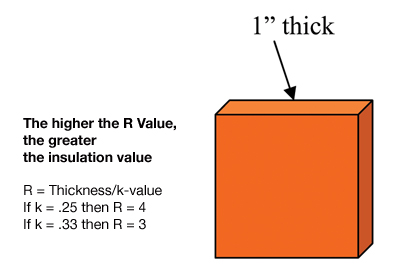
Equation 3: R-value = thickness / K-value

Thus, if the thickness is 1 inch, and the K-value is 0.25, then the R-value is 1 divided by 0.25, or 4 (leaving off the units for brevity).

U-value

Finally, there is U-value, known officially as thermal transmittance. This is more of an engineering term used to designate the thermal performance of a system as opposed to a homogeneous material. The ASTM C168 definition is as follows:

Transmittance, thermal, n: the heat transmission in unit time through unit area of a material construction and the boundary air films, induced by unit temperature difference between the environments on each side.

There are a few new terms: the boundary air films and between the environments on each side. The previous definitions did not refer to environments.

The best way to illustrate thermal transmittance or U-value is through an example. Consider the wall of a typical insulated house with nominal 2 x 4 boards (which actually measure about 1-1/2 inches x 3-1/2 inches), spaced 16 inches on center, running vertically. One might see 3/8-inch-thick gypsum wall board on the inside of the wall, with a plastic film vapor barrier separating the gypsum wall board from the wood studs. Fiberglass batts may be filling the 3-1/2-inch-wide spaces between the 2 x 4 studs. On the outside of the studs, there might be 1/2-inch-thick polystyrene insulation boards covered with exterior wood sheathing. This example will ignore doors and windows, as well as the K-value and thickness of the plastic sheet used as the vapor barrier.

The calculation of the wall’s U-value is sufficiently complex to be beyond the scope of this article, but the following values must be known or at least estimated for its thermal transmittance to be calculated: *

  • C-value of the indoor air film
  • K-value of the 3/8-inch gypsum wall board
  • K-value of the 3-1/2-inch-wide wood studs
  • Spacing between the studs (16 inches, in this case)
  • K-value of the fiberglass insulation batts, as well as their thickness (3-1/2 inches thick)
  • Width of the fiberglass batts (16 inches minus the 1-1/2 inch thickness of the wood studs = 14-1/2 inches)
  • K-value of the polystyrene boards and their thickness (1/2 inch)
  • K-value and thickness of the wood siding materials
  • C-value of the outdoor air film

The lower the U-value, the lower the rate of heat flow for a given set of conditions. A well-insulated building wall system will have a much lower U-value, or thermal transmittance, than an uninsulated or poorly insulated system.

To determine a mechanical insulation system’s U-value accurately, one must account for heat transfer through the homogeneous insulation as well as through any breaches and expansion gaps with a different insulation material. There is also the outside air film and occasionally an inside air film.

In reality, many non-homogenous portions are typically unaccounted for. The standard thermal conductivity test procedures typically treat the material as being homogeneous. In real applications, there are joints and sometimes cracks in rigid materials. These inconsistencies make the U-value greater than if the insulation behaved as a homogeneous material.

The concepts of K-value, C-value, R-value, and U-value can be summed up in the following rules:

  • The better insulated a system, the lower its U-value.
  • The greater the performance of a piece of insulation, the greater its R-value and the lower its C-value.
  • The lower the K-value of a particular insulation material, the greater its insulating value for a particular thickness and given set of conditions.

These are the properties upon which users of thermal insulation depend for energy savings, process control, personnel protection, and condensation control.

* Values for all of the above can be found in the ASHRAE Handbook of Fundamentals, Chapter 25: “Thermal and Water Vapor Transmission Data.” Chapters 23 through 26 of the same ASHRAE manual also discuss calculation of the wall’s U-value.

Figure 1

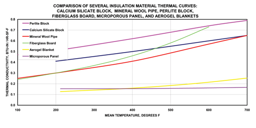
Comparison of Several Insulation Materials

Figure 2

Relationship between R-value and K-value

Figure 3

Heat transfer through a building envelope is really a function of the wall’s or roof’s U-value, not just the R-value of the thermal insulation.

Figure 4

This figure, Plate #26 from the Midwest Insulation Contractors Association (MICA) National Commercial and Industrial Insulation Standards (1999), gives an idea of why an insulation system will not perform as well as one would assume using continuous, homogeneous insulation.

Thermal insulation materials are commercially available in a variety of forms, shapes, and sizes, including blankets, boards, loose fill, pre-formed pipe, rigid foams, flexible foams, and spray foams. The materials appear to be simple but are highly engineered to optimize different properties, such as thermal performance, high-temperature performance, compressive strength, rigidity or flexibility, water repellence, flame spread prevention, inhibition of metal surface corrosion, and various health and safety considerations. To meet quality standards, these materials must retain the same properties consistently from production batch to production batch. Additionally, they often must be made in a form that is relatively easy to install so as to be economical in their final application. Each different type of material is designed to perform in particular applications over a particular temperature range.

Various organizations publish standards for thermal insulation materials and for testing and applying the materials. These include ASTM International, International Organi-zation for Standardization (ISO), and the German Institute for Standardization (DIN—Deutsches Institut fur Normung). They sometimes coordinate internationally so each type of generic material meets minimum performance criteria. Standard test procedures are used to measure performance as determined by material properties. If two companies manufacturing the same generic material use different test procedures, it is challenging and perhaps even impossible for users to compare performance of the two materials. Additionally, government organizations need to be able to specify materials using industry standards and reference standard test procedures.

ASTM materials standards can list typical or limiting values as a guide for comparing available products and making informed purchase decisions. Reference values are generally based on “average” values for typical products, but these average values must be accurately determined to serve as a useful guide. Understanding the methods used as the basis for different standards can help users choose their reference points appropriately.

Defining “Average”

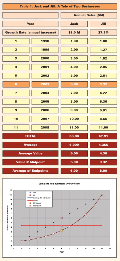
The following hypothetical situation illustrates how different approaches to averaging can yield vastly different values. Jack and his sister Jill both started businesses on January 1, 1998. Their business histories over the first 11 years show striking similarities—and differences:

  • Both businesses had sales of $1 million the first year (1998), and
  • Both businesses had sales of $11 million the eleventh year (2008).

But

  • Jack’s business increased by a steady $1 million per year over 10 years, while
  • Jill’s business increased by a steady 27 percent per year over the 10 years.

When they compared performance, they looked at “average” annual sales for the 11-year period.
Jill calculated her average three ways, getting different answers each time:

  1. She calculated total sales for all years and divided by 11: $4.336 million [=47.7 / 11]
  2. She averaged the endpoints: (Year 1 + Year 11) / 2:
    $6 million
  3. She took the sales figure for the midpoint of the range, Year 6: $3.3 million
  4. Jack calculated his average the same three ways, but he got the same result each time: $6 million.

    Figure 1 shows these values graphically so they can be more easily compared.

    What conclusions can be drawn from comparing Jack’s and Jill’s businesses?

    • With linear plots (such as Jack’s case), one can arrive at the “correct” result by averaging using a variety of methods.
    • With curved plots (such as Jill’s case), one must average using the correct way only.

    In Jill’s case, the true average is $4.336 million per year, which can be tested by multiplying it by the number of years in business to get the total sales for the period (4.336 x 11 = 47.7). But Jill’s true average is not equal to the sales figure for the “average” year, Year 6.

    The Laws of Average and Thermal Performance of Refractory Insulation Materials

    Depending on the application, refractory insulation uses two types of thermal testing standards: ASTM C201—the water calorimeter method—and ASTM C177—the guarded hot plate method. These may present a situation similar to the Jack-and-Jill example. Test method C201 measures average thermal conductivity1 taking two temperature points (one at a very low temperature and one at a very high temperature), calculating the average of those two data points, and designating that the average for the entire range. If the thermal conductivity-mean temperature relationship is linear, or nearly linear, this approach will suffice. However, for a highly non-linear relationship (i.e., a curve), the farther apart the two temperature values, the greater the potential for error. By contrast, test method ASTM C177 takes much smaller increments of temperature and represents the mean temperature as the average of those narrow increments.

    This is an important concept for anyone using ASTM standards for specifying and testing refractory insulation materials to understand because it gives context to seemingly conflicting information on limiting values for thermal conductivity in ASTM C892, “Standard Specification for High-Temperature Fiber Blanket Thermal Insulation,” published in the ASTM Book of Standards, Volume 04.06. ASTM C892 allows thermal testing to be conducted by either ASTM C177 or ASTM C201. C892 lists thermal conductivity values in two sections, one as determined by C177, and the other by C201. In most cases, the values for a specific grade at a specific mean temperature are significantly different.

    Here is an example: commonly used Grade 8 blanket insulation material. As with all insulation materials, its thermal conductivity changes with mean temperature. C892 lists quite different thermal conductivity values (one for each of the two methods) for this grade, shown in Table 2.

    The C177 values range from 33 percent greater to 1 percent lower, depending on the mean temperature. Except at a mean temperature of 2,000°F, thermal conductivity values reported using C201 simply look lower—and possibly better—than those using C177.

    Figure 2 presents the same information graphically.

    Why do the different thermal test procedures offer two different sets of results for the same material, tested at the same mean temperature? The answer appears to have two roots:

    1. Definition Difference—The thermal conductivity value listed by C201 is defined differently than that for C177, so one should not expect to find the same values listed.
    2. Different Tools Are More Accurate for Different Measurements—Despite the conflicting definitions, the two sets of numbers should be consistent after the appropriate mathematical adjustments are made; that they are not suggests that different methods are more accurate for different applications.

    Definition Difference

    With ASTM C177, the measured thermal conductivity value associated with a specific temperature is the actual value of thermal conductivity at that mean temperature—i.e., it is independent of the temperature difference (dT) involved in the measurement, provided the difference is small. One would thus measure the same value for thermal conductivity at 800°C whether hot and cold surfaces are at 850°C and 750°C, 820°C and 780°C, or 801°C and 799°C because the mean temperature is always 800° F. (Mathematically, it is the thermal conductivity one approaches, in theory, as the dT used in the measurement approaches zero.)

    In contrast, the thermal conductivity value ASTM C201 associates with 800°C is the average thermal conductivity value for a sample that spans a large dT range whose average temperature is 800°C (e.g., a dT range from 50°C to 1,550°C). The value obtained by running the test method over such a wide temperature range is generally not equal to the thermal conductivity at, in this example, 800°C; in fact, the variance using large temperature ranges can be quite large.

    The different approaches illustrate that the average thermal conductivity value over a large temperature range, in general, can be significantly different from the thermal conductivity value at the average temperature of that range. The fact that the two methods define “average thermal conductivity” somewhat differently should not necessarily present a problem to ASTM C892 users, as long as they are aware of the differences.

    Choosing the Right Method for Given Conditions

    The C201 method was originally developed for rigid, higher density refractory materials with thermal conductivity values 3 to 10 times greater than those for typical thermal insulation materials. Design limitations in the C201 apparatus limit the ability to make thermal performance determinations over the lower half of the C892 temperature range. As mean temperature increases, therefore, the correspondingly larger test temperature differences make it more difficult to devise effective thermal guarding techniques, resulting in greater measurement deviations due to increases in extraneous heat loss.

    The guarded hot plate test method that is the basis for ASTM C177 more successfully accommodates temperature ranges below 2,000°F. It is generally regarded as the method of choice for the lower half of the C892 temperature range. At temperatures above 2,000°F, however, C177 tests become increasingly difficult to conduct, and C201 becomes the better option. The two methods are thus complementary for application over the entire C892 temperature range.

    Conclusions and Recommendations

    Material and test standards for thermal insulation materials provide valuable support to specifiers, designers, and users working with high-temperature products. Thermal conductivity data tabulated in ASTM C892 is based on studies made more than 30 years ago; it may be time to reexamine the standard to enhance its usefulness. The guarded hot plate test method could be considered a primary resource for generating new thermal conductivity data, and C201 tests could be used for the top end of the temperature range. It would be important to design a coordinated program to harmonize data by the two methods in the overlapping temperature range.

    Note
    1. For thermal insulations, the correct term to use for the heat transport coefficient is “apparent thermal conductivity”—rather than simply “thermal conductivity”—to emphasize that heat moves through the insulation not only by conduction, but also by radiation (see ASTM C168 and ASTM C1045 for details). For brevity, the shorter “thermal conductivity” is used in this article, but in each case it should be understood to mean “apparent thermal conductivity.”

    References

    • ASTM C892-05, “Standard Specification for High-Temperature Fiber Blanket Thermal Insulation,” Annual Book of ASTM Standards, Vol 04.06.
    • ASTM C201-93(2004), “Standard Test Method for Thermal Conductivity of Refractories,” Annual Book of ASTM Standards, Vol 15.01.
    • ASTM C177-04, “Standard Test Method for Steady-State Heat Flux Measurements and Thermal Transmission Properties by Means of the Guarded-Hot-Plate Apparatus,” Annual Book of ASTM Standards, Vol 04.06.
    Figure 1

    Over 10 years, Jack’s business grew linearly at a rate of $1 million per year, while Jill’s grew at a rate of 27 percent per year, resulting in different revenue averages. Note that there are 11 data points, since each curve has a beginning and ending data point.

    Figure 2

    Maximum allowable thermal conductivity values for high-temperature fiber blanket thermal insulation tested using ASTM C177 and ASTM C201 test procedures (from ASTM C892, Table 1).

    Figure 3

    Thermal conductivity values based on ASTM C177 and ASTM C201 test methods.

Stacks at power generating stations are much more than tall towers used as landmarks for locating power plants. They are essential equipment needed to send the exhaust flue gas into the atmosphere. Their height and diameter are designed specifically for the plant and are usually a low- or no-maintenance item. The cost of preventing corrosion may be as little as $10,000—compared with the cost of repair or replacement, which could be double or triple that figure, as well as the costs associated with putting a plant out of commission until a stack problem is corrected. Clearly, it pays to protect stack linings.

Typical Power Plant Layout

At a typical power plant, the exit gas temperature leaving the boiler is approximately 700°F on an 800-megawatt capacity boiler. The flue gas is then passed through a large box called a selective catalytic reducer to remove nitric oxides. The gas then passes through a heat exchanger, or “air heater,” which exchanges the heat from the flue gas to heat the air used for combustion in the boiler. The flue gas leaving the air heater is around 350°F. It passes through a series of air pollution equipment to remove mercury and particulates until it gets to the induced draft fan, which pulls the flue gas through the air heater to the stack.

A typical small industrial facility like a hospital or school has boilers that are much smaller (75 megawatt or lower capacity), where the flue gas leaving the boiler is much cooler (between 351°F and 500°F). These small facilities may have a heat exchanger, such as an economizer, but not an air heater. An economizer extracts heat from the flue gas to heat the water needed in the boiler. The gas leaving the economizer is usually above 350°F, but because air pollution requirements are not currently as stringent in the industrial sector as in the power sector, the flue gas can go straight to the stack.

Corrosion Protection for Stacks

The rules for determining what a stack requires for protection against corrosion are based on the temperature of the flue gas entering the stack at full load.

  1. 130°F to 350°F
    At these low temperatures, it is recommended that the stack interior be painted or sprayed with a high, solid-type, non-asphaltic, mastic-type coating, 3/16-inch to 1/4 inch wet thickness. This type of coating will prolong the life of the stack interior by protecting against hot sulfuric, hydrochloric, and hydrofluoric acid solutions, as well as vapors present in the flue gas. The application of this mastic is usually done by painters, not bricklayers, and must be done on a dry, clean surface. For existing stacks, once it has been determined that the stack requires a mastic coating, the entire interior stack surface must be sandblasted to a near-white condition, per code SSPC-SP-10. This will ensure that the mastic material will adhere.
  2. 351°F to 400°F
    At these mid-range temperatures, the stack interior does not require an internal coating of mastic protection, but it does require external insulation and lagging to prevent condensation on the outside.
  3. 401°F to 850°F
    It has been found that if the gas temperature is in this range, no internal or external protection is required to prevent corrosion.
  4. 851°F and above
    At these elevated temperatures, the internal lining of the stack must be protected with refractory. The refractory material should match the chemistry of the acids within the flue gas. The refractory is typically made of three parts acid-resistant aggregate, one part lumnite cement. It is pneumatically or gun applied, usually 2 inches thick, through a reinforcing material such as road-mesh or chicken-wire mesh. The reinforcing mesh is held to the stack interior using stand-offs such as slab spacers, t-slot studs, or studs and nuts.

    Attention should be paid to exit flue gas temperature, especially if a different size economizer or air heater is added to the back-end of the boiler, changing the exit flue gas temperature to the stack. This change could affect the level of stack protection required to prevent corrosion.

    Stacks rarely need repair and are low-maintenance items that require attention only if they have corrosion issues. Protecting them from corrosion could save astronomical costs for repair or replacement. For example, to install a mastic coating (see item 1 above) on a 7-foot diameter, 96-foot-high existing stack operating at 300°F will require scaffolding, sand blasting, and priming and coating with the mastic, which will take approximately 6 days. Compare that to the cost of replacement: More than $250,000 for the new stack, which may take 30 days. This does not include revenue lost because the boiler cannot run without a stack.

    The bottom line: Protecting stacks from corrosion has a minimal cost compared to replacement or repair. Don’t forget stacks when making changes to the boiler.